

OOO Ventoxx Ventoxx GmbH
VentoxxUkraine Scherisberg 6
89312 Günzburg
Installation and
Operating Instructions
for the Ventilation Systems
RV by Ventoxx
OOO Ventoxx Ventoxx GmbH
VentoxxUkraine Scherisberg 6
89312 Günzburg
Manual for installation and use of Ventoxx RV ventilation systems
with heat recovery and the associated Ventoxx Twist Control.
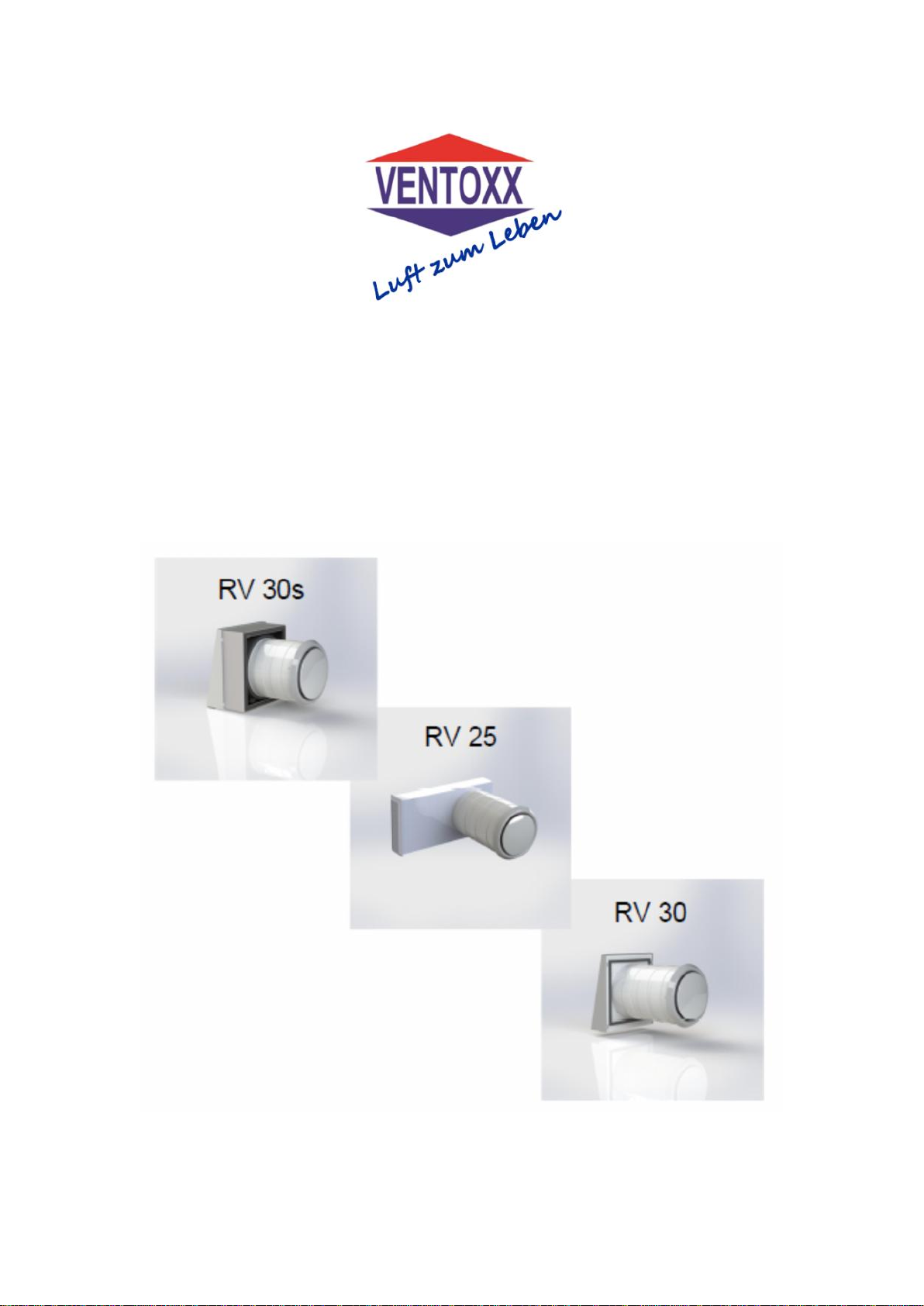
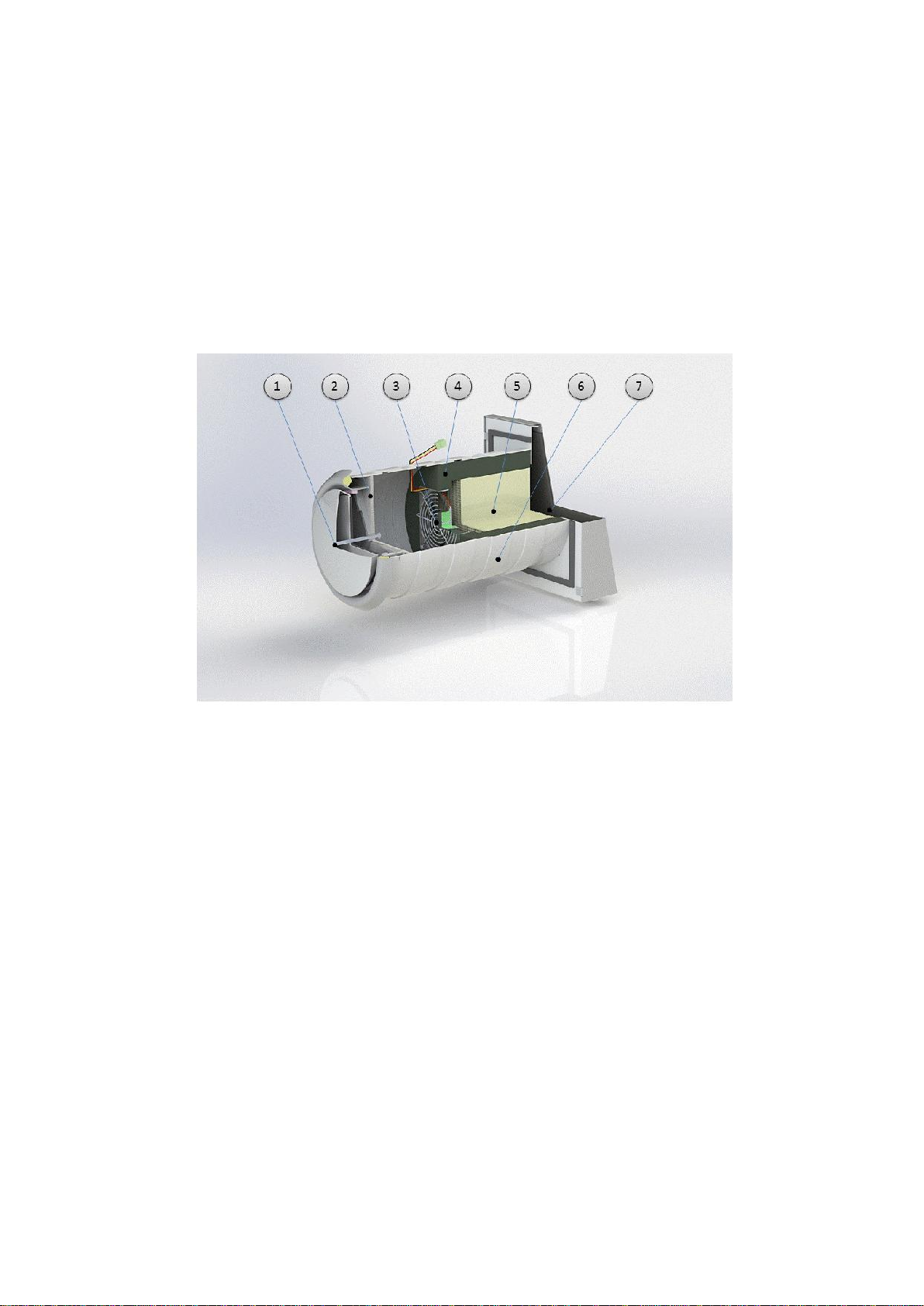
Ventoxx RV30:
Scope of Delivery:
1. Inner Cover
2. G3 Class Filter
3. Reversible Fan
4. Insulation
5. Heat Exchangers Made of Cordierite Ceramics
6. HIPS-plastic telescopic pipe with stacked rings to adjust to different wall
thickness
7. Outer Cover
OOO Ventoxx Ventoxx GmbH
VentoxxUkraine Scherisberg 6
89312 Günzburg
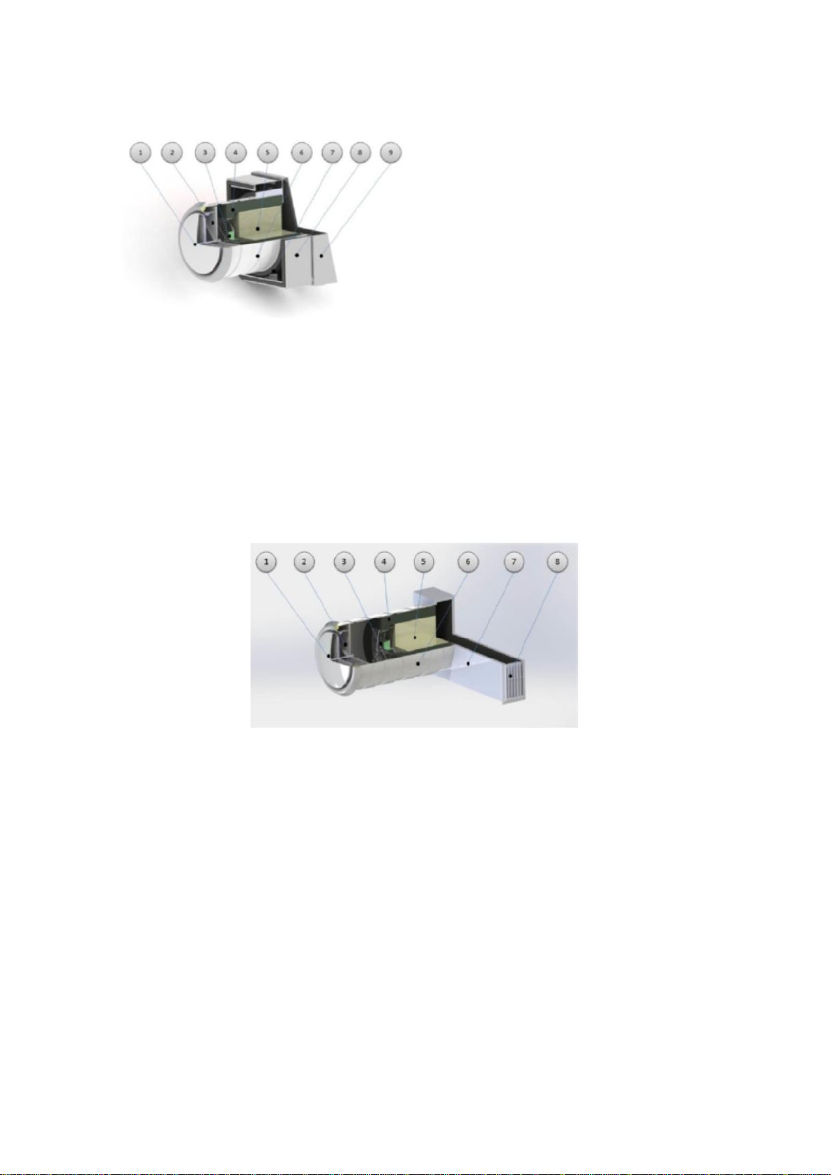
Ventoxx RV 30s:
Scope of Delivery:
1. Inner Cover
2. G3 Class Filter
3. Reversible Fan
4. Insulation
5. Heat Exchangers Made of
Cordierite Ceramics
6. HIPS-plastic telescopic pipe
with stacked rings to adjust to
different wall thickness
7. Warmer Ring
8. Compensation Box
9. Outer Cover
Ventoxx RV 25:
Scope of Delivery:
1. Inner Cover
2. G3 Class Filter
3. Reversible Fan
4. Insulation
5. Heat Exchangers Made of Cordierite Ceramics
6. HIPS-plastic telescopic pipe with stacked rings to adjust to different wall
thickness
7. Air Duct
8. Ventilation Grille for Window Opening

1
Table of Contents
1. This is the Product You Purchased:........................................................................... 3
1.1. Features and Benefits........................................................................................... 3
1.2. Technical Data....................................................................................................... 4
1.3. Quality and Warranty............................................................................................ 5
1.4. Disclaimer.............................................................................................................. 5
1.5. Safety Instructions................................................................................................ 6
2. Installation.................................................................................................................... 7
2.1. Installation Documentation .................................................................................. 7
2.2. Legal Installation Regulations.............................................................................. 7
2.3. Legal Installation Authorization........................................................................... 7
2.4. Installation in Rooms with Open Fireplaces........................................................ 7
2.5. Installation Instructions for ventilation units Ventoxx RV 30,Ventoxx RV 30s,
Ventoxx RV 25.................................................................................................................. 8
2.5.1. Tools Needed for Installation........................................................................ 8
2.5.2. Additional Accessories Needed for Installation........................................... 8
2.5.3. Placement of the Ventilation Unit.................................................................. 9
2.5.4. Allocation of the Fan.....................................................................................10
2.5.5. Installation in a New Building – Creating an Installation Opening ............10
2.5.6. Installation in an Old Building–Creating an Installation Opening..............11
2.5.7. Preparing for Installation..............................................................................12
2.5.8. Cabling...........................................................................................................12
2.5.9. Fitting of the Telescopic Pipe: Steps 1–5....................................................13
2.5.10. Installing the Piping into the Wall: Steps 6–10............................................15
2.5.11. Installation of the Outer Cover: Steps 11–13...............................................17
2.5.12. Installation of the Ventilator with Heat Exchanger Unit: Steps 14 and 15.19
2.5.13. Installation of the Inner Cover: Step 16 .......................................................20
3. Connecting Twist Control...........................................................................................20
3.1. General Information.............................................................................................20
3.1.1. Intended Use..................................................................................................20
3.1.2. Safety Instructions........................................................................................20
3.1.3. Scope of Delivery..........................................................................................20
3.2. Connection and Installation of the Control........................................................21
3.2.1. Red Fan-Blue Fan..........................................................................................21
3.2.2. Connection Scheme......................................................................................22
3.2.3. Installation of the Control: Steps 1–7..........................................................24
3.3. Commissioning and Operating ...........................................................................25
3.3.1. Commissioning.............................................................................................25

2
3.3.2. Operating.......................................................................................................25
3.3.3. Explanation for Indication ............................................................................26
3.3.4. Enabling/Disabling the Illumination for Operation Modes .........................27
3.3.5. Operation Modes of Twist Control...............................................................27
4. Maintenance and Repairs...........................................................................................29
4.1. Maintenance of the Unit.......................................................................................29
4.1.1. Filter...............................................................................................................29
4.1.2. Fan .................................................................................................................29
4.1.3. Heat Exchanger.............................................................................................29
4.1.4. Control...........................................................................................................29
4.2. Troubleshooting...................................................................................................30

3
1. This is the Product You Purchased:
… Thank you for purchasing Ventoxx GmbH product that means energy-saving ventilation of
your building! We are constantly working on improvement of our Ventoxx devices; therefore,
we welcome our customers to give their feedback on daily use experiences. Please contact us
with suggestions at: info@ventoxx.eu or visit our website at www.ventoxx.eu.
Ventilation units of RV range produced by Ventoxx Company have been developed to provide
your rooms with fresh air and remove exhaust air with minimal thermal heat losses.
The ventilation unit absorbs heat and some of the moisture from the used exhaust air and thus
enriches fresh incoming air which is supplied to the living rooms.
Whatever the season is you will get comfortable climate in your rooms, with clean and fresh
air. Ventoxxhas achieved thesehighest heat recovery rates andthushelps youto save heating
energy. In addition, the ventilation unit partially regulates the moisture balance of the air
throughout the year and helps preventing mold growth in living areas. For best results, RV
ventilation units operate in pairs.
1.1. Features and Benefits
High heat recovery and pleasant indoor climate in your bedrooms and living rooms
Low power consumption
Various possible application in new or renovated buildings
Easy installation and operating
Installation within the outer wall, and thereby no annoying superstructures inside the
room
Does not need installation of ventilation ducts, therefore is suitable for installation in
renovated buildings
Electrically safe due to low power consumption
Easy to clean, some components are partially washable
Can be controlled via Bluetooth or Smartphone (from 2017)
4
1.2. Technical Data
Nominal Volume Flow: 70% of maximum volume flow
Maximum Volume Flow
gem. VO1254/2014 EU
Characteristic Data/Operation Modes
Number of Operation Modes
17
Number of Speed Levels in Reverse
5
Ventilation Volume, m³/h
15 -55 (Level 1-5)
Ventilation volume in “Maximum
Ventilation” operation mode, m³/h
up to 110 (2 fans)
Heat Recovery Rate, %
70 – up to 83%
Noise Level, dB(A)
17 – 45
Voltage, V
230 VAC or 12 VDC
Operating Voltage, VDC
7-15
Power Consumption,q
vn
1
, W
4,4
Power Consumption at Maximum
Ventilation q
vmax
2
, W
7,4
Type of Heat Exchanger
Ceramic Heat Accumulator
(Germany)
Diameter of the Mounting Hole, mm
not less than 235
Operating Temperature, °C
-20 up to +50
Size
Minimum length of telescopic pipe – 300mm
Diameter– 226mm
Inner cover: diameter – 240 mm
Outer cover: height – 290 mm
Width – 280 mm
Type of Positioning
Horizontal placement in the outer wall
Maintenance
Filter needs to be replaced when requires.
The installed ventilation unit with heat
accumulator and filter should be checked every
3 months and cleaned if necessary.
Protection Class:
Fan
Control
IP 33
IP 20
Filter
G3
Energy Efficiency Class3A
1
2
3

5
1.3. Quality and Warranty
For production of Ventoxx ventilation systems we use materials of very high quality and
durability, which mostly come from the EU. For the complete range of our products we
provide a 24 month warranty.
The warranty period begins on the day of the invoice.
Warranty is not guaranteed if:
• the device is operated without a filter
• recommended cleaning of the filter and the heat exchanger is not performed regularly
• when the device was technically altered and/or supplemented with unauthorized by Ventoxx
components or connected differently from the installation instructions
• the device was used during site work
• the device was used for drying the rooms (e.g after plastering)
• the transformer isn’t connected properly or installed not according to the installation
instructions
If necessary, and after the warranty has expired, please contact our sales outlets. Our
specialists will check your unit and give recommendations regarding its maintenance.
1.4. Disclaimer
The contents of the present installation instructions are constantly updated and the latest
version is always available to be downloaded from the website www.ventoxx.eu.
These instructionsare in compliancewith the latest version ofthe tested Ventoxx deviceof RV
series. However, minor variations cannot be excluded so we cannot provide any guarantee
that it agrees completely.
After the completion of the installation work, these installation instructions are to be passed to
the respective user or owner. To download this document, please, go to Downloads on our
homepage www.ventoxx.eu.
The Ventoxx ventilation unit is designed for ventilation of living spaces. Improper use of the
appliance may result in damage of the device and/or cause personal injury. In this case, the
manufacturer assumes no liability.
The manufacturer is not liable for damages and losses that come from following reasons
concluded:
Non-compliance with safety rules and installation guide described in this manual or
required by law;
Lack of care for the device;
Use of materials, components and spare parts which are not authorized by the
manufacturer;
Installation onto drywall.
6
1.5. Safety Instructions
Please read the manual carefully. Here you will find important information
for installation, connection, danger prevention and proper handling of
Ventoxx devices.
This exclamation mark identifies installation and assembly situations in which
there is a high risk of personal injury or property damage, and/or calls for
increased caution to avoid personal injury or property damage.
Here notes are displayed to identify situations, which can possibly cause
problems and damage during installation and/or subsequent operation.
In these instructions you can find this sign identifying situations in which there
is a risk of electrocution. We, Ventoxx Company, encourage such operations to
be carried out by a specialized company.
7
2. Installation
2.1. Installation Documentation
2.2. Legal Installation Regulations
Please, ensure disposal of the device complies with the current building
regulations and lawful accident prevention rules in your country (get more
information with the relevant professional associations).
2.3. Legal Installation Authorization
Please,ensure strict compliance with the legal local requirements for installation
of ventilation and electrical systems in your country. Check your legal
permission for installation.
The ventilation system with heat recovery is a ‘SELV’-equipment (Safe Extra Low Voltage)
which operates only by DC power of 7-15V, however, the Twist Control is connected to 230V
AC according to legal installation authorization required in Germany.
2.4. Installation in Rooms with Open Fireplaces
In case of use of RV 30 equipment produced by Ventoxx Company in rooms
with open fireplaces or stoves, it is necessary to ensure installation complies
with the applicable rules and standards in respective country. Apart from
fireplaces with balanced flue air supply air may be needed for operation of all
other operating units with an open flame. When stoves or other built-in
components and Ventoxx devices of RV product line are used at the same time,
a prior consult from a competent regional chimneysweep is essential because
of the risk of serious personal injury andproperty damage. There is suffocation
threat!

8
2.5. Installation Instructions for ventilation units Ventoxx RV 30,Ventoxx RV 30s,
Ventoxx RV 25
2.5.1. Tools Needed for Installation
For Installation you will need the following listed tools and protective equipment.
Tools:
Level
Utility knife
Core drilling unit with 235 -240 mm drill bits for retrofitting
Phase tester (electrical fitting)
Screwdriver cross medium size (cover installation)
Wrench Size 10 (mounting outer cover)
Wire stripper (for cable mounting)
Spatula (inserting the control installation box)
Hammer and chisel or drill with drilling crown (inserting the receiving box)
Please, use the following protective equipment for installation:
Wear work gloves
Wear protective goggles
Use hearing protection
Wear head protection
Wear safety shoes
2.5.2. Additional Accessories Needed for Installation
The following additional accessories are required for installation, which are not included in the
package:
PU installation foam (please, follow the current safety regulations of your country for
using PU installation foam)
Mounting plaster
Various cables(see section 2.5.8 Cabling on page 12 for details)

9
2.5.3. Placement of the Ventilation Unit
Ventilation units of Ventoxx Companyproduct linecan beused almost in any room with exterior
wall. Due to the pendulum fan principle, the devicesmust be operated in pairs. The respective
mounting area should be here determined by a licensed professional planner.
Ventoxx Company will be pleased to
provide a preliminary design (under
Disclaimer) upon customer’s
request. When placing in the room
complies with the relevant legal
regulations and norms, the following
planning principles should be taken
into account:
Mounting height: Ventoxx devices should be mounted in normal living rooms near
the ceiling if possible, as our experience shows that it simplifies embarrassing cable
feed and ensures a better flow of air in the room.
Distance between units should not be less than 2 m.
Distance from the door: to ensure optimum room air flow, locate the device in the
furthest possible distance from the door provided that the second unit is located in
another room and possibly an intermediate room is used as an overflow chamber.
Removal of the inner panel: make sure that the selected installation site allows
unproblematic removal of the inner cover. For this, the opening must be at least 15
cm from the wall and the ceiling.
Pairwise operation: Ventoxx ventilation units should work in pairs in order to achieve
the most optimal air circulation. For proper operation of the ventilation system, free
air passage through the rooms from one device to the other must be enabled. For all
room doors either ventilation grille or a bypass (at least 5 mm) must be provided. The
room doors may not be closed airtight; otherwise the ventilation system will not work
properly as a flow between the devices cannot be guaranteed.
Mounting above the beds: we recommend refraining from installation of units
directly above the beds because a slight breeze can be felt while sleeping.

10
2.5.4. Allocation of the Fan
Ventoxx RV units work on a pendulum fan principle. In “Ventilation with Heat Recovery”
operation mode two units always work together(one as an air supply and the other as an air
outlet). The running direction will change every 68 seconds. Therefore, the factory sets
Ventoxx RV units working in opposite direction in one delivery. For this purpose the units are
marked with blue and red circles on the fan.
When installing the fans please note that the associated fans always have
different colour markers (blue and red).
2.5.5. Installation in a New Building – Creating an Installation Opening
When constructing new buildings, we recommend providing the necessary openings in the
shell of the house. By making openings, e.g., in the brickwork, with the dimensions 232 mm x
232 mm, a subsequent core drilling can be avoided.
Depending on the company and tool inventory, core drilling can be more
economical, particularly in Germany.

11
2.5.6. Installation in an Old Building–Creating an Installation Opening
To minimize additional filthy and unnecessary work during installation, we recommend core
drilling to create an opening for Ventoxx RV unit. It will also make the further steps easier.
Ensure the drill bit can provide an opening of 230-240 mm. The opening should also have a
slight slope to the outside (2 degrees).
When drilling a wall opening, make sure:
That no people can be injured and/or object can be damaged by the fall out of wall
fractions;
No wires or pipes are available in the drilled wall;
That the hole does not influence the bearing capacity of the wall;
That creation of an opening has no effect on the physics of the building, e.g.,
penetration of vapour control or rain protection path;
That all necessary protective equipment is applied.

12
2.5.7. Preparing for Installation
The following steps should be taken before the professional installation:
Unpack the unit.
Check the completeness of the contents. Your delivery has the following
components:
1 x Ventilator with Heat Exchanger Installation Unit
1 x Piping Segment Consisting of 3 Elements Assembled
2 x Round-head Screws with Square Neck
2 x Screw Nuts
1 x Inner Cover
1 x Outer Cover
1 x Sealing Ring (Self-Adhesive )
Remove the installation unit (ventilator with heat exchanger) from the piping and
secure it against damage such as knocks or contamination.
The heat exchanger is made of ceramics and can be easily damaged by knocks
or falling!
2.5.8. Cabling
Cable Connecting
To connect the control in the provided location, the room must have 230 V cabling. In the new
building, in particular, at least one empty wiring conduit leading to the place of future control is
recommended to be provided before plastering.
Please, note that this service can only be provided by an authorized supplier
representative (e.g., electrician) in Germany.
Cabling Ventoxx RV ventilation units
Low-voltage cables must lead from the control to the relevant associated fans. For this a wiring
with a cable cross-section 3 x 0.75mm² is sufficient. As a power feed cable (connection
between electrical power network and transformer) a wiring with a cable cross-section not less
than 3 x 1.5mm² is sufficient. Please, note that there should be enough overhang at both ends
to connect the control and the fan. An overhang of 40 cm should be provided.
In an old building, laying low voltage cabling in corners and under wallpaper is
recommended to ensure minimum intervention to the existing inventory.

13
2.5.9. Fitting of the Telescopic Pipe: Steps 1–5
When assembling and installing the telescopic pipe, deformations must be
avoided! The form of the ventilator with heat exchanger installation unit is
accurately adapted to the pipe!
It is necessary to leave the space between the wall and the pipe. The inner-side
vapour barrier must be connected to the unit, if available. The same applies to
an external rain protection path, if available. There is a threat of penetration of
condensate due to an improperly attached vapour barrier or penetration of
driving rain by improperly connected rain protection path!
The standard telescopic pipe can be built into the wall of maximum thickness of
310 mm. If your building hasthicker walls, you need additional pipe elements for
piping system (please, specify the wall thickness when ordering, the required
additional elements are included in a separate packaging).
Step 1
Accurately measure the total outer wall thickness (including plaster layer). Add extra 10 mm.
Step 2
The piping is pre-assembled. You can supplement the piping inside, as appropriate, by the
necessary elements to the pipe length determined in Step 1:
Inner Outer

14
Step 3
If necessary, correct the insertion depth of the pipe segments in order to obtain the necessary
pipe length depending on the wall thickness.
Step 4
Insert the carriage bolts into the provided openings of the future front side of the pipe. The
screw head must point to the room (the necessary screws are included).
Step 5
Then glue one self-adhesive sealing ring in the inside of the pipe, as shown below.

15
2.5.10. Installing the Piping into the Wall: Steps 6–10
During installation of the piping system into the wall, note the following things:
The pipe must be pre-assembled as described in2.5.9, completely and tightly
The ventilator with heat exchanger installation unit is not used in the piping
The opening in the wall is free of dust and debris
Step 6
Slide the pre-assembled pipe into the opening. There should a little slope of the piping to the
outside (about 2%) to ensure the further condensation drainage.
Observe the mounting direction. The screws must face
the front side.
.
Ensure the placement of the outside carriage bolts (fastening the outer cover) is
horizontal. Vertical and horizontal mounting of the outer cover is dependent
thereon.
.
Inside out view from the pipe
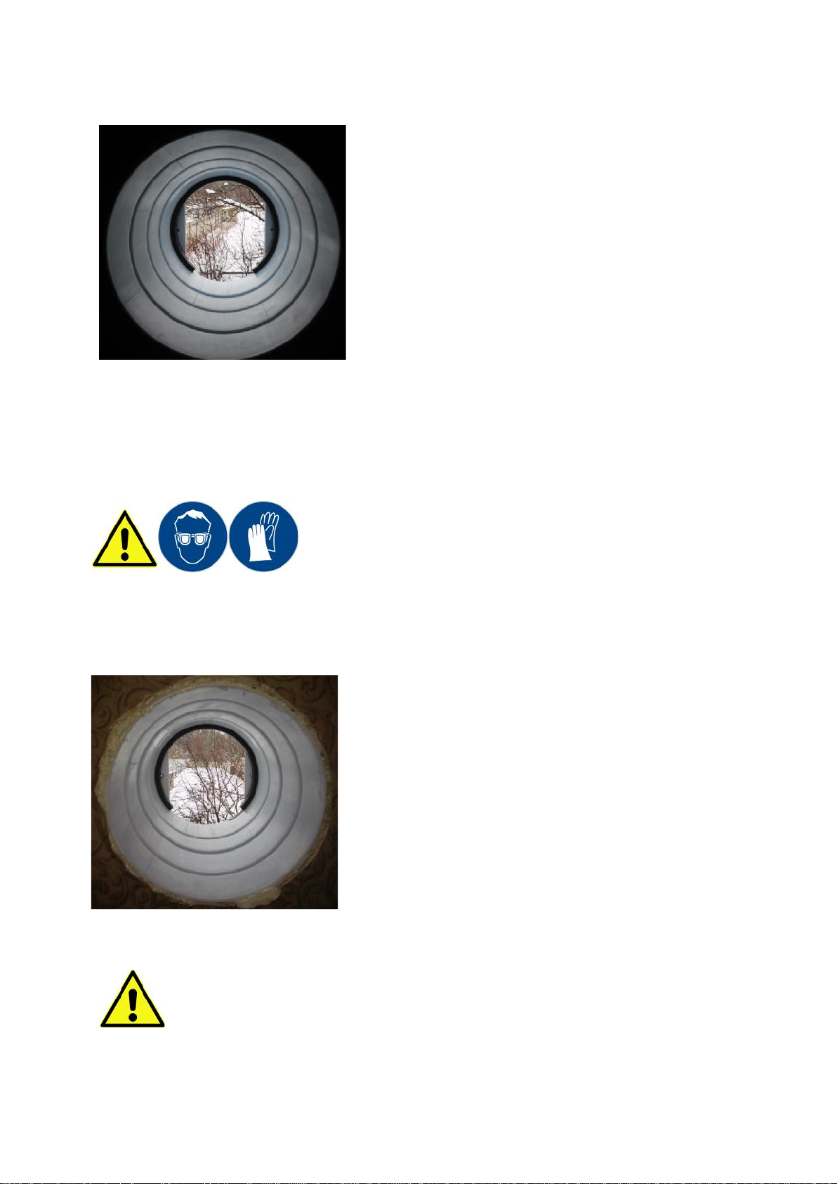
16
Step 7
Turn the pipe into the correct position. Fix the pipe so
that the sealing ring on the pipe top comes to rest. Insert
the enclosed wedges to secure the position of the tube.
Wedge the pipe on four sides.
Step 8
Check there is sufficient slope of piping to the outside (about 2%), and the position of the
screws on the front side is horizontal.
Step 9
Wear work gloves and protective goggles to protect your
eyes from contamination and damage with PU mounting
foam! Please follow safety instructions for installing the
product you are using.
Seal the pipe with PU mounting foam. It is necessary to
leave the space between the wall and the pipe to ensure
a stable position of the piping.
Please keep in mind connecting a vapour barrier and rain protection path to
avoid structural damage!
Further installation steps may be takenonly after hardening of PU-foam. Please
follow the manufacturer’s instructions for hardening time for polyurethane foam.

17
Step 10
Insert the unit control connection cable into the pipe. The cabling between the
control and theunitis provided. The actual connection of the control is described
hereinafter (see how to do this in chapter 3 of these instructions).
2.5.11. Installation of the Outer Cover: Steps 11–13
When installing the cover, please, ensure there is sufficient stability of your
footprint. Secure yourself against falling hazard. If necessary, please, check the
current statutory safety regulations.
Step 11
Attach the mounting panel of the outer cover to the outer wall using the screws and nuts
supplied.
Due to the outer wall flatness tolerances, installation of
the outer cover can be difficult. Therefore, we
recommend the mounting screws not to be over
tightened.
Step 12
Insert the outer cover to the mounting panel.

18
Step 13
UV-resistant silicone can be used to close the top and
side gaps between the outer cover and the wall.
Please note: silicone joints are maintenance
joints.
After installation of the pipe and the outer cover, the
ventilation system RV 30should be installed as follows:
After installation of the pipe and the additional
compensation box, as well as the attachment of the
outer cover on the compensation box, the ventilation
system
RV 30s should be installed as follows:
After installation of the pipe and the additional air duct
on the piping, as well as the attachment of the
ventilation grille to the air duct, the ventilation system
RV 25 should be installed as follows:
the ventilation grille sits in the window reveal,
the ventilation duct sits hidden in the facade insulation.
19
2.5.12. Installation of the Ventilator with Heat Exchanger Unit: Steps 14 and 15
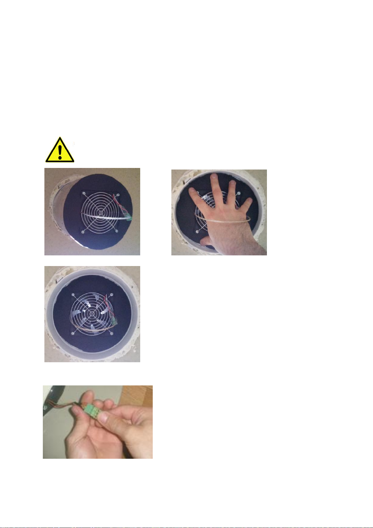
Step 14
Insert the ventilator with heat exchanger installation unit into the pipe. (The fan should point
in the direction of the interior). The unit is set horizontally and then pushed with light pressure
into the pipe.
For the drainage of the possibly accumulating condensation water in the heat exchanger, the
ventilator with heat exchanger installation unit must be pushed to the end of the telescopic
pipe. Thus the noise in the living room caused by the unit will be reduced, too.
Be careful when inserting the ventilator with heat exchanger installation unit to avoid
pressure on the fan! Only the edges of the installation unit (foam) can be pressed.
Step 15
Connect the connection cable to the fan according to
the connection scheme (see chapter 3.2. of these
instructions).
20
2.5.13. Installation of the Inner Cover: Step 16
Step 16
Insert the inner cover. Turn the inner cover clockwise to close. To open, turn it anti-clockwise.
Close the inner cover when Ventoxx ventilation unit is off (for example, in strong winds, to
avoid noise and drafts).
3. Connecting Twist Control
3.1. General Information
3.1.1. Intended Use
Ventoxx Twist Control is used to operate Ventoxx RV ventilation units. When installed and
used as intended, connection and operation of the controller constitutes no danger to people
or property.
If the controller is used for other purposes than stated herein, there can
be threats of injury or damage. The manufacturer or supplier is not liable
for any damages arising from improper use. The risk is borne by the user
only.
3.1.2. Safety Instructions
Risk of injury!Improper installation and connection to the power supply system
can cause personal injury or property damage. Please, carefully follow all the
relevant regulations for connection of electrical equipment and accident
prevention applicable in your country.
Connection of control and/or fan to 230V voltage leads to certain damage and
loss of equipment. There is a risk of serious personal injury due to electrocution!
3.1.3. Scope of Delivery
The necessary control for the operation of the device is not normally included in
the standard packaging of Ventoxx ventilation unit but is delivered separately
packed.

21
3.2. Connection and Installation of the Control
3.2.1. Red Fan-Blue Fan
The centre of the front of each our reversible fans is marked with a blue or red circle. As our
system works in pendulum fan method, ensure that each system has the same number of
blue and red fans.
Please also note this when connecting the units.
1) Control: Input Voltage
12V DC
2) Front Panel
3) Transformer (for connection of up
to 4 units)
4) Flush-Mounted Box
22
When a system has two fans of the same colour marking installed, they
operate in the same direction and not as a pendulum version. Accordingly,
there can be no heat recovery.
3.2.2. Connection Scheme
Since Ventoxx ventilation units and Ventoxx Twist Control will be built-in, you
should ask the representatives of the manufacturer or a specialist for an advice
about the choice of installation locations.
When choosing the installation location for
the control, it should be noted that certain
operating modes of the ventilation units
provide the supply of fresh air of the
outside temperature. In case of work in
lower temperatures for long hours (for
example, in winter) this can lead to negative
results.
Any number of ventilation units can be
connected to the Ventoxx Twist Control.
However, please, make sure that sufficient
power is fed into the power grid. The power
and control unit are installed in the fans
themselves. The control gives the fan only the
command for controlling the operation
modes.
Note that Twist Control and RV
ventilation units are never supplied
with 230V AC; only low-voltage
current may be applied. 230V electricity will
destroy the device and lead to a significant
risk of injury due to electrocution.
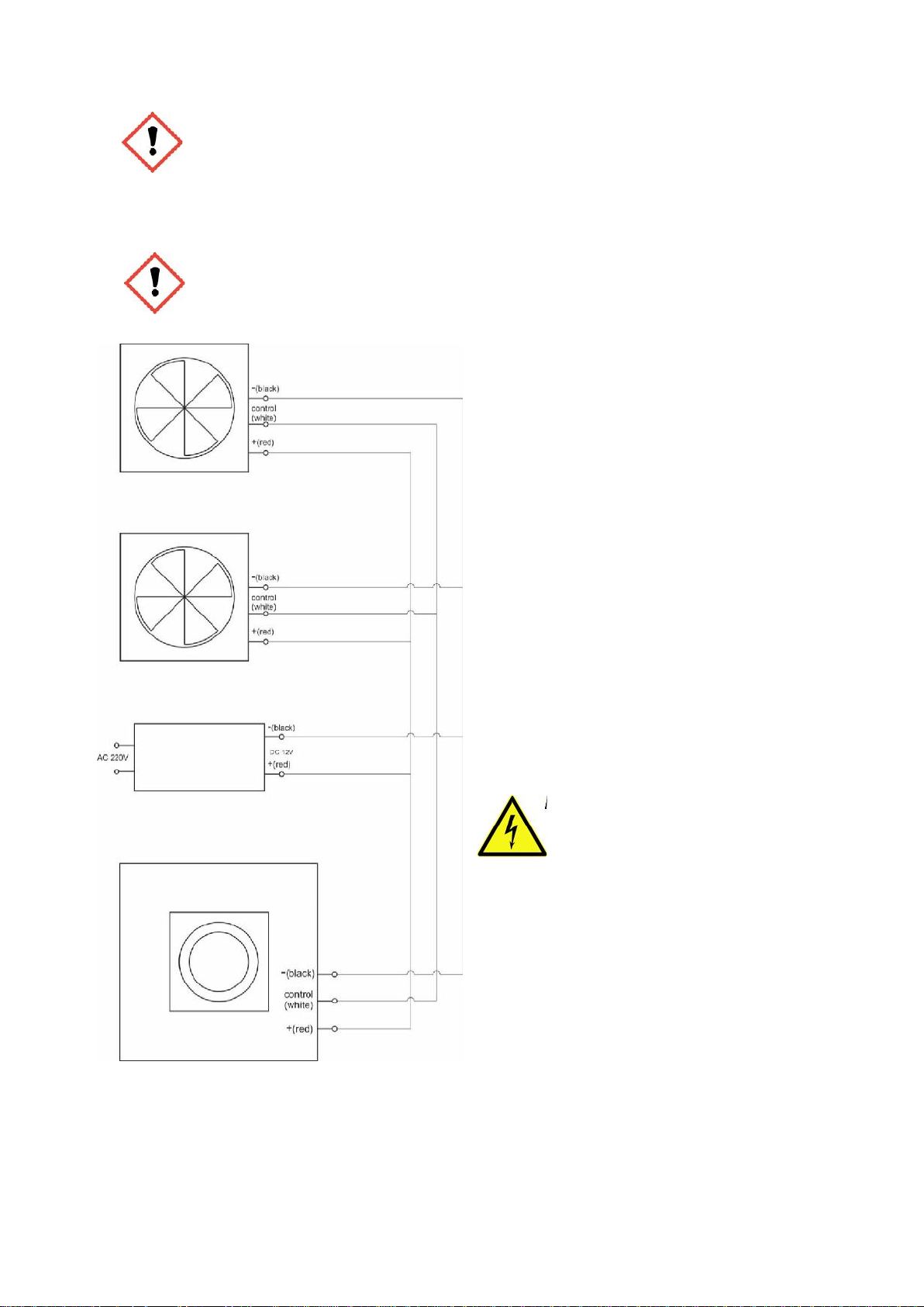
This standard connection scheme shows the optimal choice for the installation location. The
power supply can be placed at any point of the electricity circuit.

23
Please also consider the following connection options. Below, possible variations are shown
schematically:
A standard transformer with 25W output is suitable for connection of up to 4 ventilation units.
In case of connecting more than four ventilation units, more network capacity is required (5W
per unit).
Please also note the maximum cable lengths for star-shaped connection cables of
30m. If the ventilation units are connected in series, the maximum cable length can
be 20m. The maximum cable length is the maximum distance from the control to
the last connected ventilation unit.

24
3.2.3. Installation of the Control: Steps 1–7
Step 1
For installation of the control into the wall, two core holes of 65mm diameter (and breaking the
in-between gap) and 70 mm depth are required. The required size of the space for the
installation box is approx. 65 x 65 x 140 mm.
Step 2
Lay the cables and connect them to the system according to the scheme above. The
recommended cable cross section size is 3 x 0.75 mm².
Step 3
Attach the installation box of the control into the wall.
Step 4
Connect the 220V power supply to the power connecting part using the cable connector (4).
Step 5
Connect the 12V lead wire as shown on the picture:

25
Step 6
Install the control into the installation box.
Install the control so that the manufacturer's name could be read (i.e. the name
is written horizontally).
Step 7
Cover the control with the front panel (2) and fasten it with a little pressure.
3.3. Commissioning and Operating
3.3.1. Commissioning
The electrical installation and initial commissioning should be carried out by qualified
personnel.
3.3.2. Operating
Ventoxx Twist Control providessimple and intuitive control for Ventoxx RV,your new ventilation
system. It allows calling all functions with just a central knob (Master Switch).

26
3.3.3. Explanation for Indication
The optical display is located around the knob and is only visible when
switched on. In the pictures, the visual illumination in each specific case
is shown.
Green LEDs above (On/Speed):
The top row of LEDs in green shows the speed at which the ventilation
units are currently working. Here one LED lit up means the lowest fan
speed and five LEDs mean the highest fan speed. Thus, 5 different speed
levels can be set for your ventilation units. Turning the knobclockwise will
increase the fan speed. Rotating anti-clockwise, you will reduce the fan
speed.
Red LED down left (Off):
The red LED on the bottom left side means that the ventilation units are
turned off but the power is supplied to the control.
Blue LED downright (Ventilation):
The blue LED on the bottom right side shows that the unit is currently
working in the "Ventilation" operating mode.
This means that the devices connected to this control work without heat
recovery (fans operate without changing direction/reversing) and the air
led into the rooms has outside temperature.
Different LEDs are lit up simultaneously:
Simultaneously lit up LEDs for speed (green) and ventilation (blue)
mean that the ventilation units are in the "Ventilation" operating mode
and work at the specified speed.

27
3.3.4. Enabling/Disabling the Illumination for Operation Modes
If necessary, you can turn off LED illumination. In order to do that press and hold the knob for
about 3 seconds. The ventilation system is now working in the operating mode selected
previously. Whenthe setoperation mode is changed, the corresponding LEDlights up briefly
(approx. for 1 sec).
To switch on the illumination of the control press it and holdthe knobpressed for about 3
seconds.
3.3.5. Operation Modes of Twist Control
3.3.5.1. Operation Mode “Ventilation with Heat Recovery”
When turning the knob of the control clockwise, only one
green LED lit up shows the first speed, if two diodes are on –
it is the second speed, etc. In this mode the ventilation system
most efficiently saves the heat from the consumed air in the
heat storage and enriches the incoming fresh outside air with
this heat.
When the device is reversing, it is indicated by the blinking of
the blue LED. The ventilation unites reversing every 68
seconds. This visual illumination only means that the fans have
changed the direction of rotation (the function appears only
when the illumination is activated).
The best results are achieved when the unit is
steadily running on low levels 1-2. In addition to
high heat gain, the noise level is the lowest!
3.3.5.2. Operation Mode “Ventilation at the Selected Speed”
By pressing the rotary knob when " Ventilation with Heat
Recovery " operation mode is activated, the blue LED lights
are on and the ventilation units start working in "Ventilation"
operation mode which means that the reversing is switched
off and cold air of an outside temperature flows into the
rooms.

28
By pressing the knob again, the blueLED begins to flash, which
means that the ventilation units work in the "Ventilation"
operating mode but have changed the direction of air flow, for
example, when in room 1 the ventilation unit has been working
to supply air and in room 2 – to let exhaust air out, therefore,
air will be removed from room 1 and let inside in room 2.
To switch off the "Ventilation" operation mode, you have to use
the control knob only one step to any other speed.
To start the "Ventilation" operation modeat different speed, you
have to select the required speed and then press the knob.
This working mode has no automatic shutdown
and is only switched off when turning the knob.
3.3.5.3. Operation Mode “High-PerformanceVentilation”
To start this operation mode you have to switch off the
ventilation units by turning the knob of the control anticlockwise until a red LED lights up. Now please press the knob
until the blue LED lightsup. The ventilation units are now
working in the "High-PerformanceVentilation" operation
mode.Press the knob againto switch tothe other direction. Here
the blue LED begins to flash like in the “Ventilation at the
Selected Speed” operation mode.
After about 10 minutes this modewill automatically switchoff
and the system will continue operating as ventilation with heat
recovery. By pressing the knob you return to the "Ventilation
with Heat Recovery" mode.
3.3.5.4. Operation Mode “Power Off”
To turn off the device turn the knob of the control anticlockwise until the red LED light up.

29
4. Maintenance and Repairs
Before you start any kind of maintenance, switch Ventoxx RV units off
and disconnect them from the power supply. The ceramic heat
exchanger is fragile, do handle it carefully and do not let it fall.
4.1. Maintenance of the Unit
4.1.1. Filter
The filter is suitable for long-term use. Cleaning is carried out under running water. If damaged,
the filter must be replaced.
Filter requires changing or cleaning every three months. A flashing red LED on the control
indicates that.
4.1.2. Fan
The condition of the fan should be checked annually. Even if the filter is cleaned regularly, a
small amount of dust can stick to the fan. This may lead to lower efficiency. The fan can be
cleaned with airflow or with a soft sponge or brush.
4.1.3. Heat Exchanger
We recommend annual check of heat exchange unit. If there is contamination of the heat
exchanger, proceed as follows:
Turn the power off
Remove the inner cover and the filter
Disconnect the electrical terminal
Get the ventilator unit removed from the piping
Carefully remove the fan from the ventilator unit
Now the heat exchanger can be cleaned with a vacuum cleaner or a damp cloth.
We recommend you to avoid cleaning the unit in the dishwasher not to damage
the insulation!
4.1.4. Control
The control itself does not require any special cleaning. Should there be any cleaning of
Ventoxx RV unit or its filter change, yet the fans must be turned off via the control (see
operating modes).

30
4.2. Troubleshooting
If there is any unexpected malfunction of your Ventoxx RV device, try the following to fix the
simplest problems:
Problem
Possible Solution: Please, check…
Low airflow
You notice that airflow is
too low
the fan speed set, and, if necessary, set a higher fan
speed (see 3.3.5.2)
the inner cover panel - it must be open; if it is not, open it
the dust filter: check it for dirt and clean if necessary (see
4.1.1)
the heat accumulator: it could also be contaminated. If
this is the case, please clean it (see 4.1.3)
Cold airflow
You felt that air flow is too
cold
whether the ventilation units are connected in
accordance with the installation instructions. A red and a
blue fan are always working as a pendulum unit (see
2.5.4)
if the device is working in the "High-Performance
Ventilation", and, therefore, there is no heat recovery.
Please, adjust to “Ventilation with Heat Recovery"
operation mode (see 3.3.5.1)
Strange noise
My fan is making strange
sounds ...?
if the ventilator with heat exchanger installation unit is
installed according to the instructions? Perhaps, it is
mounted into the pipe too close to the inner wall of the
house. Then it should be pushed further into the pipe.
Please, install the unit according to the instructions (see
2.5.12)
if the fan is dirty or an alien object is in the fan? – Please,
clean it and remove any alien objects (see 4.1.2)
the set fan speed; perhaps, it is too high. Reduce the fan
speed (see 3.3.5.2)
Stoppage of the Fans:
My fan stopped working…?
if the fan has been connected properly?
if there is a power supply to the fan?
if the control has been connected properly?
If the control has been connected according to the
instructions?
If your answer to all the above mentioned questions is "yes",
there may be a defective control or a defective fan. In this
case, please, contact one of our dealers.

31
EC Conformity Declaration
Manufacturer: OOO Ventoxx
Description: Decentralized Ventilation Unit with Heat Recovery
Model: RV Range
Directives: 2006/42/EC, 89/366/EEC, 92/31/EEC, 93/68/EEC
Standards: DIN EN 60335-1, DIN EN 61000-3-2, DIN EN 61000-6-3: 2007
Ventoxx GmbH
Scherisberg 6
89312Günzburg
Germany
Telephone: 08221/9362213
E-Mail: info@ventoxx.eu
Managing Directors:
Florian Lammeyer, Thomas Rusch
Trade Register: Memmingen District Court, HRB 16731
Tax ID Number: DE 305338563
Any kind of duplication is only permitted with permission of Ventoxx GmbH.
 Loading...