

Ventmatika EKA 250, EKA 100, EKA 125, EKA 160, EKA 250-12kW Technical Data, Mounting, Maintenance
...
ELECTRICAL CIRCULAR DUCT HEATERS
EKA
ELECTRICAL CIRCULAR DUCT HEATERS
EKA
Technical data
Mounting
Maintenance

ELECTRICAL CIRCULAR DUCT HEATERS
EKA
1
Electrical duct heaters EKA are designed to heat fresh air in ventilation systems. Casing (EKA
protection class IP 44, except EKA Type NV which protection class IP 30) is made from Aluzinc coated
steel which is high temperature proof and with rubber seals for duct connection. Heating elements
tube is made from stainless steel AISI 304. There are 2 protection thermostats and screw terminals
for easy connection installed in the heaters.
Heaters can be installed horizontally with the electrical connection box facing upwards or
sideways and vertically (only if the air flow direction upwards). The air velocity in the duct of the
heater must be 1,5 m/s minimum. The maximum temperature of the output is 50 °C.
k
D B
C
D
50 50
A
D+63 B
PS PS C
D
50 50
A
≤1,5 kW (1~230V)
<3,0 kW (2~400V); ≤3,0 kW (3~400V)
Description
Dimensions

ELECTRICAL CIRCULAR DUCT HEATERS
EKA
2
D+25 B
C
D
50 50
A
D+25+63 B
PS PS C
D
50 50
A
>1,5 kW (1~230V)
≥3,0 kW (2~400V); >3,0 kW (3~400V)

ELECTRICAL CIRCULAR DUCT HEATERS
EKA
3
Heater type
A(mm)
B(mm)
C(mm)
D(mm)
EKA 100
370
276
71
100
EKA 125
370
276
71
125
EKA 160
370
276
71
160
EKA 200
370
276
71
200
EKA 250
370
276
71
250
EKA 250-12kW
500
402
71
250
EKA 250-15kW
630
532
71
250
EKA 315
373
276
71
315
EKA 315-12kW
500
402
71
315
EKA 315-15kW
630
532
71
315
EKA 315-18kW
630
532
71
315
EKA 355
373
276
71
355
EKA 355-12kW
500
402
71
355
EKA 355-15kW
630
532
71
355
EKA 355-18kW
630
532
71
355
EKA 400
373
276
81
400
EKA 400-12kW
500
402
81
400
EKA 400-15kW
630
532
81
400
EKA 400-18kW
630
532
81
400
EKA 400-21kW
770
672
81
400
EKA 400-24kW
880
782
81
400
EKA 450
373
276
81
450
EKA 450-12kW
500
402
81
450
EKA 450-15kW
630
532
81
450
EKA 450-18kW
630
532
81
450
EKA 450-21kW
770
672
81
450
EKA 450-24kW
880
782
81
450
EKA 500
373
276
81
500
EKA 500-12kW
500
402
81
500
EKA 500-15kW
630
532
81
500
EKA 500-18kW
630
532
81
500
EKA 500-21kW
770
672
81
500
EKA 500-24kW
880
782
81
500

ELECTRICAL CIRCULAR DUCT HEATERS
EKA
4
Heater type
Diameter
(mm)
Min. airflow
(m³/h)
Power supply
(VAC/50Hz)
Power
(kW)
Available
heating
elements (kW)
EKA 100
100
45
1~230
0,3...1,8
0,3
EKA 125
125
70
1~230
0,3...3,6
0,3/0,6
EKA 160
160
110
1~230
0,3...7,2
0,3/0,6/1,0/1,2
2~400
1,0...6,0
1,0
3~400
3,0...6,0
1,0
EKA 200
200
170
1~230
0,3...7,2
0,3/0,6/1,0/1,2
2~400
1,0...6,0
1,0
3~400
3,0...9,0
1,0/1,5
EKA 250
250
265
1~230
0,3...7,2
0,3/0,6/1,0/1,2
2~400
1,0...9,0
1,0/1,5
3~400
3,0...9,0
1,0/1,5
EKA 250-12kW
250
265
3~400
12,0
1,0/1,5
EKA 250-15kW
250
265
3~400
15,0
1,0/1,5
EKA 315
315 425
1~230
0,6...9,0
0,6/1,0/1,2
2~400
1,0...9,0
1,0/1,5
3~400
3,0...9,0
1,0/1,5
EKA 315-12kW
315
425
2~400
12
1,0/1,5
3~400
12
1,0/1,5
EKA 315-15kW
315
425
2~400
15
1,0/1,5
3~400
15
1,0/1,5
EKA 315-18kW
315
425
2~400
18
1,0/1,5
3~400
18
1,0/1,5
EKA 355
355
535
1~230
0,6...9,0
0,6/1,0/1,2
2~400
1,0...9,0
1,0/1,5
3~400
3,0...9,0
1,0/1,5
EKA 355-12kW
355
535
2~400
12
1,0/1,5
3~400
12
1,0/1,5
EKA 355-15kW
355
535
2~400
15
1,0/1,5
3~400
15
1,0/1,5
EKA 355-18kW
355
535
2~400
18
1,0/1,5
3~400
18
1,0/1,5
EKA 400
400
680
1~230
0,6...9,0
0,6/1,0/1,2
2~400
1,0...9,0
1,0/1,5
3~400
3,0...9,0
1,0/1,5
EKA 400-12kW
400
680
1~230
9
1,0
2~400
12
1,0/1,5
3~400
12
1,0/1,5
EKA 400-15kW
400
680
1~230
12
1,0
2~400
15
1,0/1,5
3~400
15
1,0/1,5
Technical data
ELECTRICAL CIRCULAR DUCT HEATERS
EKA
5
EKA 400-18kW
400
680
2~400
18
1,0/1,5
3~400
18
1,0/1,5
EKA 400-21kW
400
680
3~400
21
1,0/1,5
EKA 400-24kW
400
680
3~400
24
1,0/1,5
EKA 450
450
860
1~230
0,6...9,0
0,6/1,0/1,2
2~400
1,0...9,0
1,0/1,5
3~400
3,0...9,0
1,0/1,5
EKA 450-12kW
450
860
1~230
9
1,0
2~400
12
1,0/1,5
3~400
12
1,0/1,5
EKA 450-15kW
450
860
1~230
12
1,0
2~400
15
1,0/1,5
3~400
15
1,0/1,5
EKA 450-18kW
450
860
2~400
18
1,0/1,5
3~400
18
1,0/1,5
EKA 450-21kW
450
860
3~400
21
1,0/1,5
EKA 450-24kW
450
860
3~400
24
1,0/1,5
EKA 500
500
1060
1~230
0,6...9,0
0,6/1,0/1,2
2~400
1,0...9,0
1,0/1,5
3~400
3,0...9,0
1,0/1,5
EKA 500-12kW
500
1060
1~230
9
1,0
2~400
12
1,0/1,5
3~400
12
1,0/1,5
EKA 500-15kW
500
1060
1~230
12
1,0
2~400
15
1,0/1,5
3~400
15
1,0/1,5
EKA 500-18kW
500
1060
2~400
18
1,0/1,5
3~400
18
1,0/1,5
EKA 500-21kW
500
1060
3~400
21
1,0/1,5
EKA 500-24kW
500
1060
3~400
24
1,0/1,5
Heaters conforms to requirements of standards:
LST EN 60335-2-30:2003+A1:2005+A2:2007
LST EN 60335-2-30:2010+AC:2010+A11:2012 (EN 60335-2-30:2009+AC:2010+A11:2012)
and therefore complies with the essential requirements and provisions of the 2006/95/EC
and 2004/108/EC Directives.
The CE mark is affixed.

ELECTRICAL CIRCULAR DUCT HEATERS
EKA
6
EKA 100-0.3-1f PS without integrated control
1 2 3 4
1 – Duct diameter (mm)
100 – 100 mm 200 – 200 mm 355 – 355 mm 500 – 500 mm
125 – 125 mm 250 – 250 mm 400 – 400 mm
160 – 160 mm 315 – 315 mm 450 – 450 mm
2 – Heating power (kW)
0.3 – 0,3 kW ... 24.0 – 24,0 kW
3 – Input voltage:
1f – Single phase 230V
2f – 2-phase 400V
3f – 3-phase 400V
3f – 3-phase 230V (on request)
4 – Additional accessories:
PS – Differential pressure switch for air flow detection
EKA NV 100-0.3-1f PTC/2NTC with integrated controller
1 2 3 4 5
1 – Control type:
NV – Potentiometer on the top of the heater casing for temperature control
NI – External wired remote setpoint knob (TR5K) for temperature control
NIS – External wired remote (0…10) VDC signal for temperature control (analog input)
ESKM – External wired remote PWM (ON/OFF: ON (6…24) VDC) signal for temperature control
MB – External wired remote temperature control via Modbus RTU protocol (RS485)
2 – Duct diameter (mm)
100 – 100 mm 200 – 200 mm 355 – 355 mm 500 – 500 mm
125 – 125 mm 250 – 250 mm 400 – 400 mm
160 – 160 mm 315 – 315 mm 450 – 450 mm
3 – Heating power (kW)
0.3 – 0,3 kW ... 24.0 – 24,0 kW (NV, NI, NIS,MB)
0.3 – 0,3 kW ... 15.0 – 15,0 kW (ESKM)
4 – Input voltage:
1f – Single phase 230V
2f – 2-phase 400V
3f – 3-phase 400V
3f – 3-phase 230V (on request)
Model marking

ELECTRICAL CIRCULAR DUCT HEATERS
EKA
7
5 – Additional accessories:
PS – Differential pressure switch for air flow detection
PTC – Sensor for minimum air velocity detection
PTC/PS – Sensor for minimum air velocity detection and diff. pressure switch for air flow detection
PTC/K – Sensor for minimum air velocity detection and contactor for overheating protection
PH – Sensor for minimum air velocity detection and diff. pressure switch for air flow detection
2NTC – 2 sensors for the air temperature measuring
PTC/2NTC – Sensor for min. air velocity detection and 2 sensors for the air temperature measuring
In the electrical duct heaters EKA are installed two thermostats for overheating protection. The
first one with automatic reset, turns off the heating when the temperature reaches 50 °C and turns
on when the temperature drops below 50 °C. The second with manual reset, turns off the heating
when the temperature reaches 100 °C. Only way to reset it, push the reset button on the top of the
casing (see mounting examples) when the temperature drops below 100 °C.
In the heaters EKA ESKM are installed additional thermostat (with automatic reset) for
controller ESKM overheating protection. This thermostat turns off the heating when the temperature
reaches 70 °C and turns on when the temperature drops below 70 °C.
Electrical duct heaters EKA can be installed horizontally in any position except electrical
connection box downward and vertically (only if the air flow direction upwards) (see Fig. 1).
Fig. 1. Heaters installation positions
Heaters can’t be installed in explosive and aggressive substances environment. Heaters can be
used only for the clean air heating or preheating. Heaters intended only for inside installation. If
heater is installed in such way that can be accidental contact with heating elements, protective grill
must be installed. The air velocity in the duct of the heater must be 1,5 m/s minimum.
Overheating protection
Installation and electrical connection

ELECTRICAL CIRCULAR DUCT HEATERS
EKA
8
IMPORTANT:
The installation to the mains power supply may only be wired by a competent electrician. The
power supply cable must be selected in the ratio with power of the heater. When installing these
heaters, the standards and regulations in force in your country must be followed strictly adhered to.
Within the installation an electrical isolation automatic circuit breaker (not included) must be present,
to enable the installer to cut all power supply lines. Automatic circuit breaker must be selected
regarding power and nominal current (see the electrical rating plate on the heater casing top) of the
heater and should have characteristic B. Connect the heater to the mains power supply, check that
the voltage, frequency, power and current are the same as those indicated on the electrical rating
plate. The heater must be earthed.
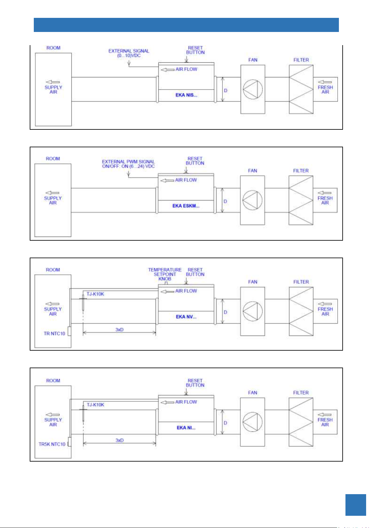
We recommend install supply air temperature sensor in distance multiplied by the heater’s
diameter (3xD). For example: heater EKA diameter 200 mm, sensor’s installation distance will be:
3x200=600 mm.
Fig. 2. Mounting example EKA NV…
Fig. 3. Mounting example EKA NI…
ELECTRICAL CIRCULAR DUCT HEATERS
EKA
9
Fig. 3. Mounting example EKA NIS…
Fig. 4. Mounting example EKA ESKM…
Fig. 5. Mounting example EKA NV…2NTC…
Fig. 6. Mounting example EKA NI…2NTC…

ELECTRICAL CIRCULAR DUCT HEATERS
EKA
10
AHU – Air handling unit
Fig. 7. Mounting example EKA NV… (Preheater)
AHU – Air handling unit
Fig. 8. Mounting example EKA NI… (Preheater)
AHU – Air handling unit
Fig. 9. Mounting example EKA NIS… (Preheater)
AHU – Air handling unit
Fig. 10. Mounting example EKA ESKM… (Preheater)
ELECTRICAL CIRCULAR DUCT HEATERS
EKA
11
Heaters EKA with integrated temperature controller EKR-KN… (See Fig. 11) can be controlled in
five different ways depending on control type:
Type EKA NV – potentiometer on the top of the heater casing for temperature control
Type EKA NI – external wired remote setpoint knob (TR5K) for temperature control
Type EKA NIS – external wired remote 0…10V signal for temperature control
Type EKA ESKM – external wired remote PWM (ON/OFF: ON(6…24)VDC) signal for temp. control
Type EKA MB – external wired remote temperature control via Modbus RTU protocol (RS485)
Electrical duct heaters EKA with integrated temperature controller EKR-KN… works by PID
regulator. That enable fine temperature control. Controller EKR-KN… controls load by Triacs without
moving parts, which causes no-noise commutation.
Table 1. Technical characteristics of controller EKR-KN...
Power supply depending on model
single phase 230V / 2 - phase 400V / 3 - phase 400V
Power consumption in standby mode
0,1VA
Ambient temperature
0...50 °C
Relative humidity
Max. 90 % RH (non-condensing)
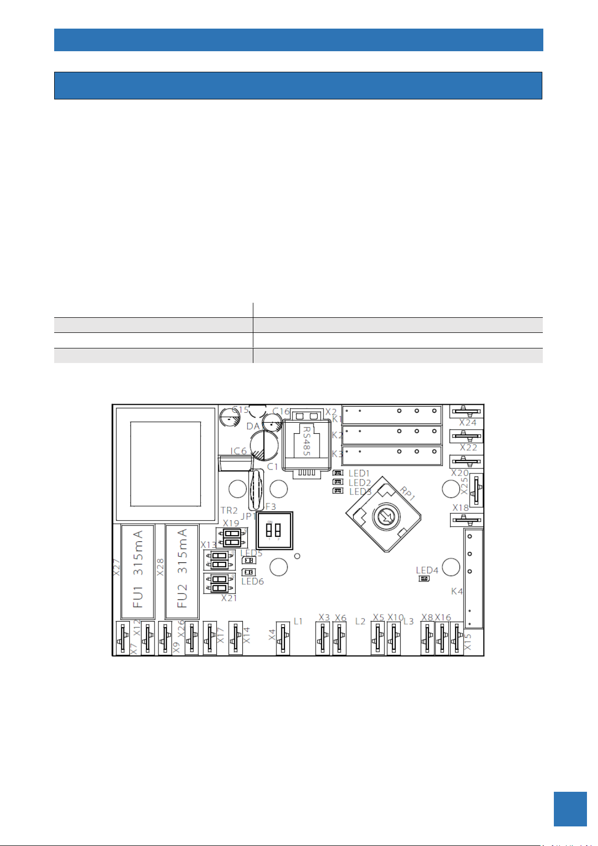
Fig. 11. Print circuit board (PCB) of temperature controller EKR-KN…
(View may vary depending on type EKR-KN)
Heaters EKA with integrated controller
ELECTRICAL CIRCULAR DUCT HEATERS
EKA
12
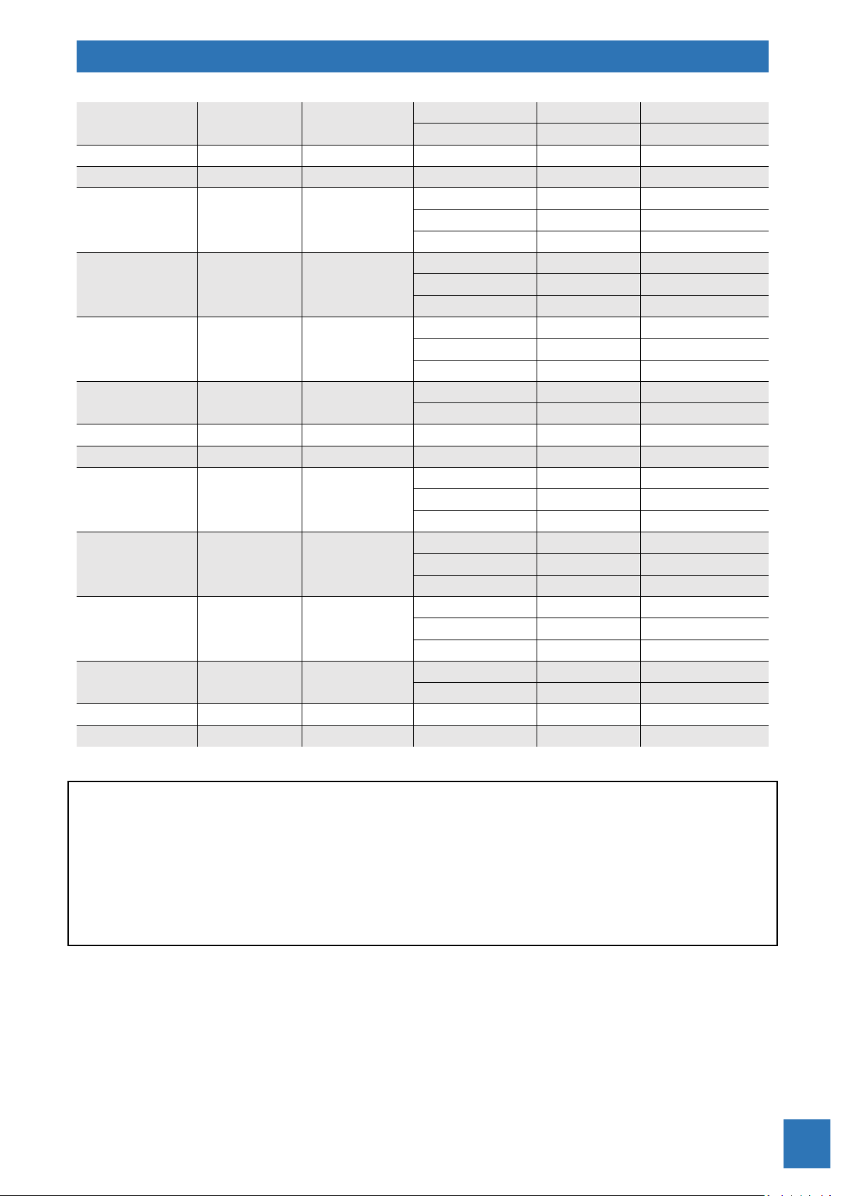
Heaters EKA without integrated control can be controlled with external controllers (listed
below) with one or two air temperature sensors (ordered separately), depending on operating mode.
Type
Voltage
Input/Output
Controlled
Max. load
(kW)
Additional
Steps*/Max. load
(kW)
Total load
(kW)
Controlled
Max.
current (A)
EKR 6.1
1~230/1~230
3,2 - 3,2
16
2~400/2~400
6,4 - 6,4
EKR 15.1
3~230/3~230
9
1/9
18
25
3~400/3~400
15
1/15
30
EKR 15.1P
3~230/3~230
9
4/135
144
25
3~400/3~400
15
4/225
240
EKR 30.1
3~230/3~230
15
1/15
30
45
3~400/3~400
30
1/30
60
EKR 30.1P
3~230/3~230
15
4/225
240
45
3~400/3~400
30
4/450
480
* – relay outputs (5A/230V) intended for contactors control. For more information read
controllers user guide.
External controllers for the heaters EKA

ELECTRICAL CIRCULAR DUCT HEATERS
EKA
13
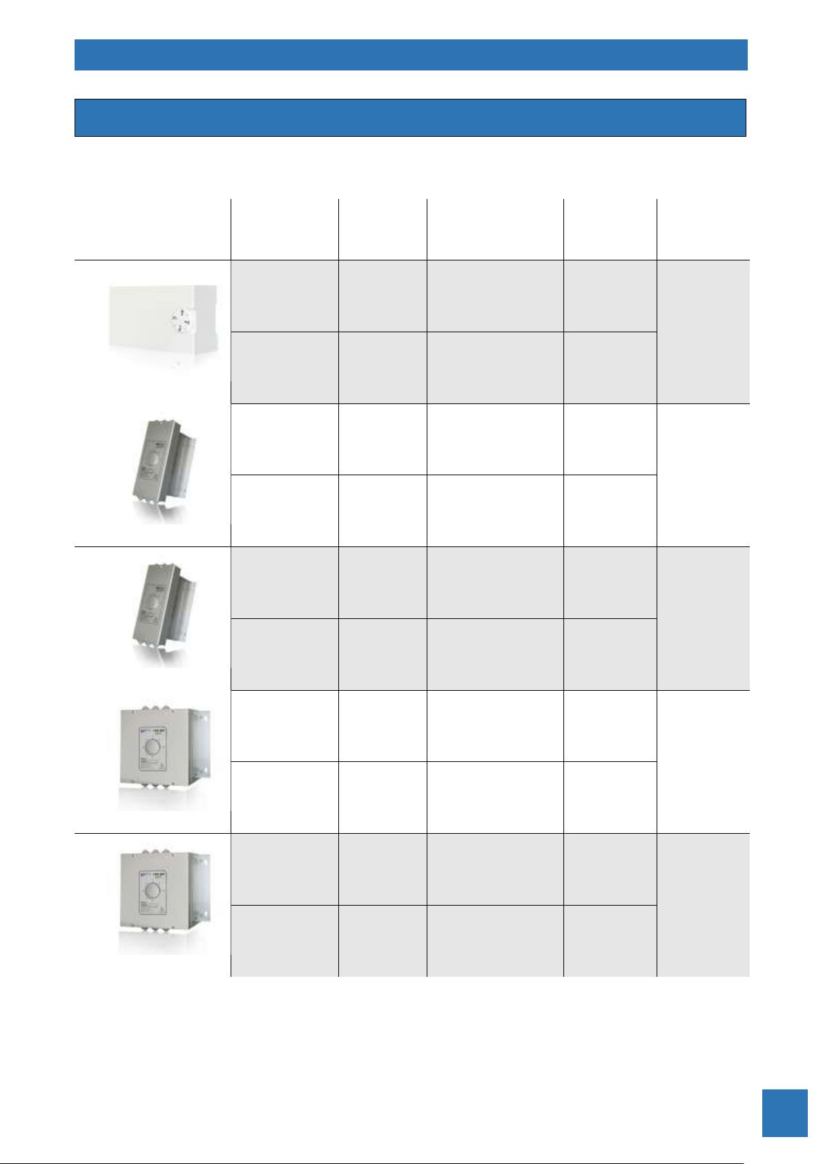
Additional accessories (ordered separately) intended for use with external and integrated
controllers are listed below:
Type
Description
Measurement range
(°C)
Setpoint range
(°C)
TJ-K10K
Duct temperature
sensor
-30...105
-
TR NTC10
Room temperature
sensor panel
-30...105
-
TR5K NTC10
Room temperature
sensor panel with
setpoint knob
-30...105
0...30
TR5K
External remote
panel with
setpoint knob
-
0...30
For more information read accessories user guide.
Additional accessories for the controllers

ELECTRICAL CIRCULAR DUCT HEATERS
EKA
14
Heater type
Temperature control type
Setpoint range
EKA NV...
Potentiometer on the top of the heater casing
(0...30) °C*
EKA NI...
External wired remote panel with setpoint knob (TR5K)
(0...30) °C
EKA NIS...
External wired remote (0...10) VDC signal (analog input)
P**×(0...100) %
EKA ESKM...
External wired remote PWM (ON/OFF: ON (6…24) VDC) signal
P**×(0...100) %
EKA MB...
External wired remote control via Modbus RTU protocol (RS485)
(0...30) °C or
P**×(0...100) %
* – other setpoint range on request
** – power of the heater (kW)
Electrical duct heaters EKA NV … are designed with integrated temperature control, one
temperature sensor, potentiometer on the top of the heater casing for temperature setpoint.
When the heater power supply is switched on, LED 6 on the controller (EKR-KN…) PCB (see Fig.
11) flashes once every 8 seconds if setpoint is 0 °C and every second if setpoint is higher than 0 °C. If
controller turns on the heating depending on the demand, LED 5 lights (see Fig. 11).
Heaters EKA NV … operates by the supply (TJ-K10K) air temperature sensor. Setpoint
temperature (0…30) °C.
There can be set the different desired (setpoint) air temperature by potentiometer on the top
of the heater casing.
If LED 6 lights continuously it means that there is a failure of: supply (TJ-K10K) air temperature
sensor or potentiometer on the top of the heater casing.
IMPORTANT: If failure appears, power supply must be switched off and only then performed
fault elimination works.
Electrical duct heaters EKA NI … are designed with integrated temperature control, one
temperature sensor, wired remote control panel (TR5K) for temperature setpoint.
When the heater power supply is switched on, LED 6 on the controller (EKR-KN…) PCB (see Fig.
11) flashes once every 8 seconds if setpoint is 0 °C and every second if setpoint is higher than 0 °C. If
controller turns on the heating depending on the demand, LED 5 lights (see Fig. 11).
Heaters EKA NI … operates by the supply (TJ-K10K) air temperature sensor. Setpoint
temperature (0…30) °C.
There can be set the different desired (setpoint) air temperature by wired remote control panel.
If LED 6 lights continuously it means that there is a failure of: supply (TJ-K10K) air temperature
sensor or wired remote control panel TR5K.
Description of control type
Description of operating EKA NV …
Description of operating EKA NI …

ELECTRICAL CIRCULAR DUCT HEATERS
EKA
15
IMPORTANT: If failure appears, power supply must be switched off and only then performed
fault elimination works.
Electrical duct heaters EKA NIS … are designed for the heaters power (0…100) % control by
analog signal input (0…10) VDC.
When the heater power supply is switched on, LED 6 on the controller (EKR-KN…) PCB (see Fig.
11) flashes every second. If controller turns on the heating depending on analog signal, LED 5 lights
(see Fig. 11).
Electrical duct heaters EKA NV … PTC … are designed with integrated temperature control, PTC
(air velocity) and temperature sensors, potentiometer on the top of the heater casing for
temperature setpoint.
When the heater power supply is switched on, controller (EKR-KN…) is in preparing mode for 30
seconds, LED 1 flashes once every 5 seconds. If there is air velocity (Min. 1,5 m/s) in the duct heater
after preparing mode, LED 1 flashes once per second and controller turns on the heating depending
on the demand, LED 2 lights. If there is no air velocity, controller don’t turns on the heating till air
velocity appears.
Heaters EKA NV … PTC … (PH) operates by the supply (TJ-K10K) air temperature sensor. Setpoint
temperature (0…30) °C.
There can be set the different desired (setpoint) air temperature by potentiometer on the top
of the heater casing.
If LED 1 lights continuously it means that there is a failure of: PTC (air velocity) sensor, supply
(TJ-K10K) air temperature sensor, potentiometer on the top of the heater casing.
When the heater power supply is switched on, after power supply interruption or after any
failure, controller is in preparing mode for 30 seconds.
IMPORTANT: If failure appears, power supply must be switched off and only then performed
fault elimination works.
Electrical duct heaters EKA NI … PTC … (PH) are designed with integrated temperature control,
PTC (air velocity) and temperature sensors, wired remote control panel (TR5K) for temperature
setpoint.
When the heater power supply is switched on, controller (EKR-KN…) is in preparing mode for 30
seconds, LED 1 flashes once every 5 seconds. If there is air velocity (Min. 1,5 m/s) in the duct heater
after preparing mode, LED 1 flashes once per second and controller turns on the heating depending
on the demand, LED 2 lights. If there is no air velocity, controller don’t turns on the heating till air
velocity appears.
Description of operating EKA NIS …
Description of operating EKA NV … PTC … (PH)
Description of operating EKA NI … PTC … (PH)

ELECTRICAL CIRCULAR DUCT HEATERS
EKA
16
Heaters EKA NI … PTC … (PH) operates by the supply (TJ-K10K) air temperature sensor. Setpoint
temperature (0…30) °C.
There can be set the different desired (setpoint) air temperature by wired remote control panel.
If LED 1 lights continuously it means that there is a failure of: PTC (air velocity) sensor, supply
(TJ-K10K) air temperature sensor, wired remote control panel TR5K.
When the heater power supply is switched on, after power supply interruption or after any
failure, controller in preparing mode for 30 seconds.
IMPORTANT: If failure appears, power supply must be switched off and only then performed
fault elimination works.
Electrical duct heaters EKA NIS … PTC … (PH) are designed for the heaters power (0…100) %
control by analog signal input (0…10) VDC and with integrated PTC (air velocity) sensor.
When the heater power supply is switched on, controller (EKR-KN…) is in preparing mode for 30
seconds, LED 1 flashes once every 5 seconds. If there is air velocity (Min. 1,5 m/s) in the duct heater
after preparing mode, LED 1 flashes once per second and controller turns on the heating depending
on analog signal, LED 2 lights. If there is no air velocity, controller don’t turns on the heating till air
velocity appears.
If LED 1 lights continuously it means that there is a failure of PTC (air velocity) sensor.
When the heater power supply is switched on, after power supply interruption or after any
failure, controller is in preparing mode for 30 seconds.
IMPORTANT: If failure appears, power supply must be switched off and only then performed
fault elimination works.
Electrical duct heaters EKA NV … 2NTC are designed with integrated temperature control, two
temperature sensors, potentiometer on the top of the heater casing for temperature setpoint.
When the heater power supply is switched on, LED 6 on the controller (EKR-KN…) PCB (see Fig.
11) flashes once every 8 seconds if setpoint is 0 °C and every second if setpoint is higher than 0 °C. If
controller turns on the heating depending on the demand, LED 5 lights (see Fig. 11).
Heaters EKA NV … 2NTC operates by the supply (TJ-K10K) and by the room (NTC10) air
temperature sensor. Setpoint temperature (15…30) °C. In this mode is preprogrammed the minimum
(15°C) and the maximum (45°C) temperatures of supply air. The room air temperature sensor is
mounted in the wired panel TR NTC10.
There can be set the different desired (setpoint) air temperature by potentiometer on the top
of the heater casing.
If LED 6 lights continuously it means that there is a failure of: supply (TJ-K10K) or room (NTC10)
air temperature sensor, potentiometer on the top of the heater casing.
Description of operating EKA NV … 2NTC
Description of operating EKA NIS … PTC … (PH)

ELECTRICAL CIRCULAR DUCT HEATERS
EKA
17
IMPORTANT: If failure appears, power supply must be switched off and only then performed
fault elimination works.
Electrical duct heaters EKA NI … 2NTC are designed with integrated temperature control, two
temperature sensors, wired remote control panel (TR5K NTC10) for temperature setpoint.
When the heater power supply is switched on, LED 6 on the controller (EKR-KN…) PCB (see Fig.
11) flashes once every 8 seconds if setpoint is 0 °C and every second if setpoint is higher than 0 °C. If
controller turns on the heating depending on the demand, LED 5 lights (see Fig. 11).
Heaters EKA NI … 2NTC operates by the supply (TJ-K10K) and by the room (NTC10) air
temperature sensor. Setpoint temperature (15…30) °C. In this mode is preprogrammed the minimum
(15°C) and the maximum (45°C) temperatures of supply air. The room air temperature sensor is
mounted in the wired remote control panel TR5K NTC10.
There can be set the different desired (setpoint) air temperature by wired remote control panel
TR5K NTC10.
If LED 6 lights continuously it means that there is a failure of: supply (TJ-K10K) or room (NTC10)
air temperature sensor, wired remote control panel TR5K NTC10.
IMPORTANT: If failure appears, power supply must be switched off and only then performed
fault elimination works.
Electrical duct heaters EKA NV … PTC/2NTC are designed with integrated temperature control,
PTC (air velocity) and two temperature sensors, potentiometer on the top of the heater casing for
temperature setpoint.
When the heater power supply is switched on, controller (EKR-KN…) is in preparing mode for 30
seconds, LED 1 flashes once every 5 seconds. If there is air velocity (Min. 1,5 m/s) in the duct heater
after preparing mode, controller turns on the heating depending on the demand, LED 2 lights. If there
is no air velocity, controller don’t turns on the heating till air velocity appears.
Heaters EKA NV … PTC/2NTC can operate in two modes:
1. Control by the supply air temperature sensor (TJ-K10K), when the first (1) switch of JP1 (see
Fig. 11) is in position OFF. LED 1 flashes once per second. Setpoint temperature (0…30) °C.
2. Control by the supply (TJ-K10K) and by the room (NTC10) air temperature sensor, when the
first (1) switch of JP1 (see Fig. 11) is in position ON. LED 1 flashes twice per second. Setpoint
temperature (15…30) °C. In this mode is preprogrammed the minimum (15°C) and the
maximum (40°C) temperatures of supply air. The room air temperature sensor is mounted
in the wired panel TR NTC10.
Depending on the operating mode there can be set the different desired (setpoint) air
temperature by potentiometer on the top of the heater casing.
Description of operating EKA NV … PTC/2NTC
Description of operating EKA NI … 2NTC

ELECTRICAL CIRCULAR DUCT HEATERS
EKA
18
If LED 1 lights continuously it means that there is a failure of: PTC (air velocity) sensor, supply
(TJ-K10K) or room (NTC10) air temperature sensor, potentiometer on the top of the heater casing.
When the heater power supply is switched on, after power supply interruption or after any
failure, controller is in preparing mode for 30 seconds.
IMPORTANT: If failure appears, power supply must be switched off and only then performed
fault elimination works.
Electrical duct heaters EKA NI … PTC/2NTC are designed with integrated temperature control,
PTC (air velocity) and two temperature sensors, wired remote control panel (TR5K NTC10) for
temperature setpoint.
When the heater power supply is switched on, controller (EKR-KN…) is in preparing mode for 30
seconds, LED 1 flashes once every 5 seconds. If there is air velocity (Min. 1,5 m/s) in the duct heater
after preparing mode, controller turns on the heating depending on the demand, LED 2 lights. If there
is no air velocity, controller don’t turns on the heating till air velocity appears.
Heaters EKA NI … PTC/2NTC can operate in two modes:
1. Control by the supply air temperature sensor (TJ-K10K), when the first (1) switch of JP1 (see
Fig. 11) is in position OFF. LED 1 flashes once per second. Set point temperature (0…30) °C.
2. Control by the supply (TJ-K10K) and by the room (NTC10) air temperature sensor, when the
first (1) switch of JP1 (see Fig. 11) is in position ON. LED 1 flashes twice per second. Setpoint
temperature (15…30) °C. In this mode is preprogrammed the minimum (15°C) and the
maximum (40°C) temperatures of supply air. The room air temperature sensor is mounted
in the wired remote control panel TR5K NTC10.
Depending on the operating mode there can be set the different desired (setpoint) air
temperature by wired remote control panel TR5K NTC10.
If LED 1 lights continuously it means that there is a failure of: PTC (air velocity) sensor, supply
(TJ-K10K) or room (NTC10) air temperature sensor, wired remote control panel TR5K NTC10.
When the heater power supply is switched on, after power supply interruption or after any
failure, controller is in preparing mode for 30 seconds.
IMPORTANT: If failure appears, power supply must be switched off and only then performed
fault elimination works.
Description of operating EKA NI … PTC/2NTC

ELECTRICAL CIRCULAR DUCT HEATERS
EKA
19
Electrical duct heaters EKA MB … can communicate via Modbus RTU. Connected to the system
EKA MB … is a Slave device. Modbus settings are shown in table 2.
Table 2. Modbus settings
Setting
Possible values
Default value
Device address
1...247
10
Baud rate
2400, 4800, 9600, 19200, 38400
9600
Parity
None, Even, Odd
None
Stop bit
None, 1, 2
1
There is connection provided on the PCB for Modbus (see Fig. 11). Connector pin layout and
meanings are shown in Fig. 12.
Fig. 12. Connector for Modbus control
+12VDC
B-
A+
GND
For detailed information about control via Modbus please contact manufacturer.
Description of operating EKA MB …
ELECTRICAL CIRCULAR DUCT HEATERS
EKA
20
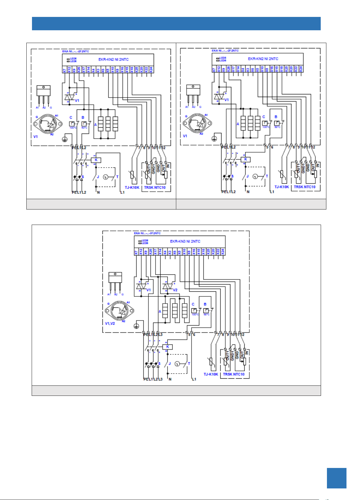
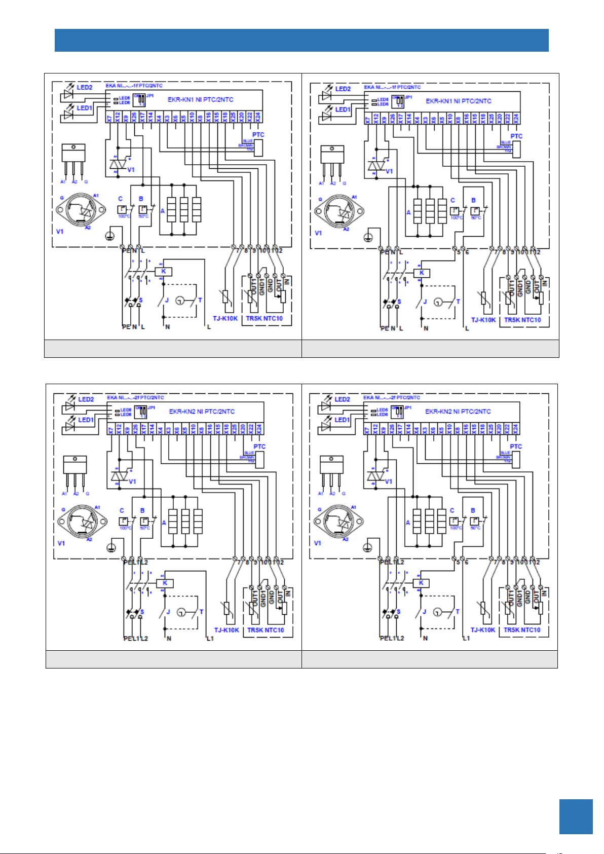
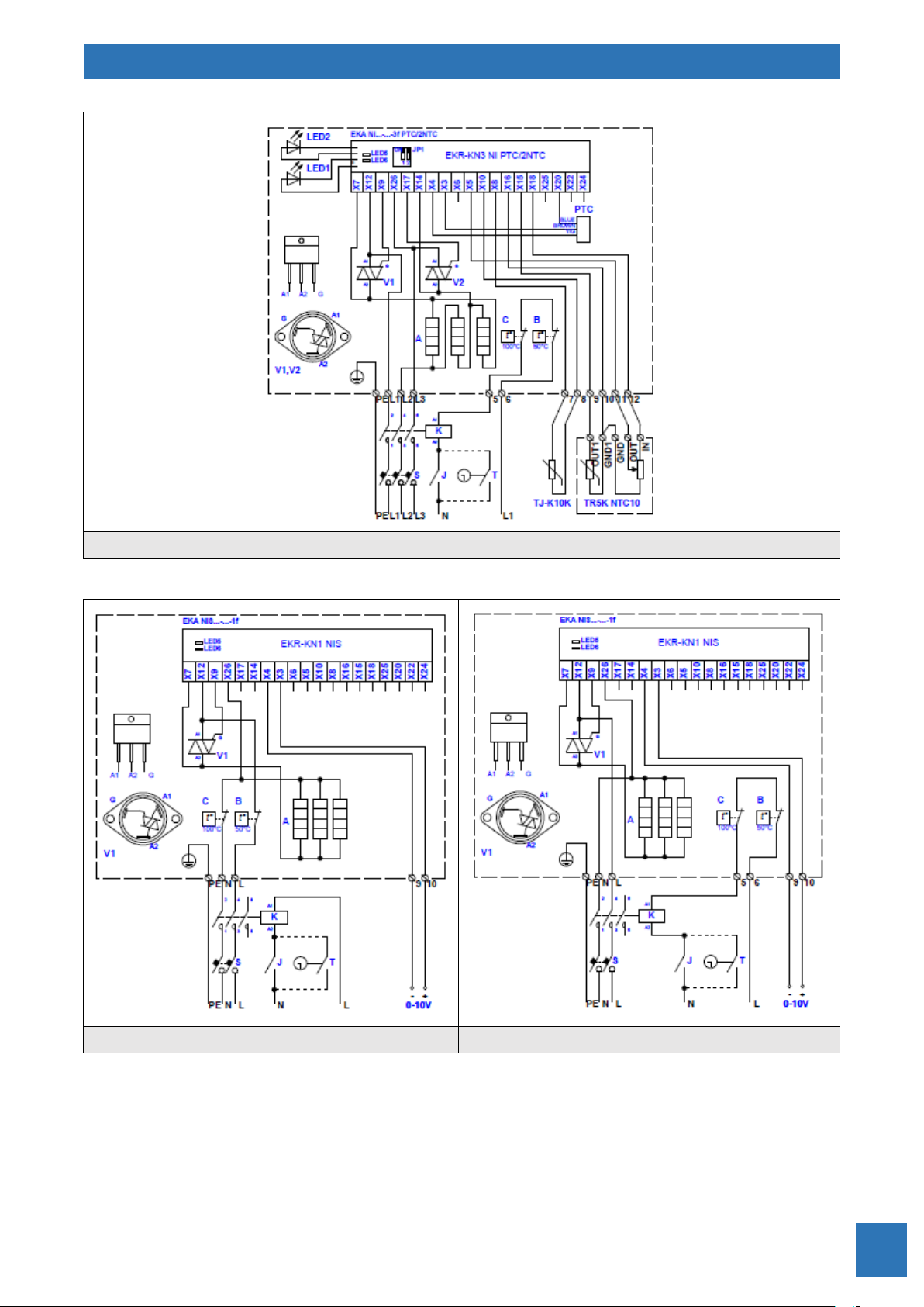
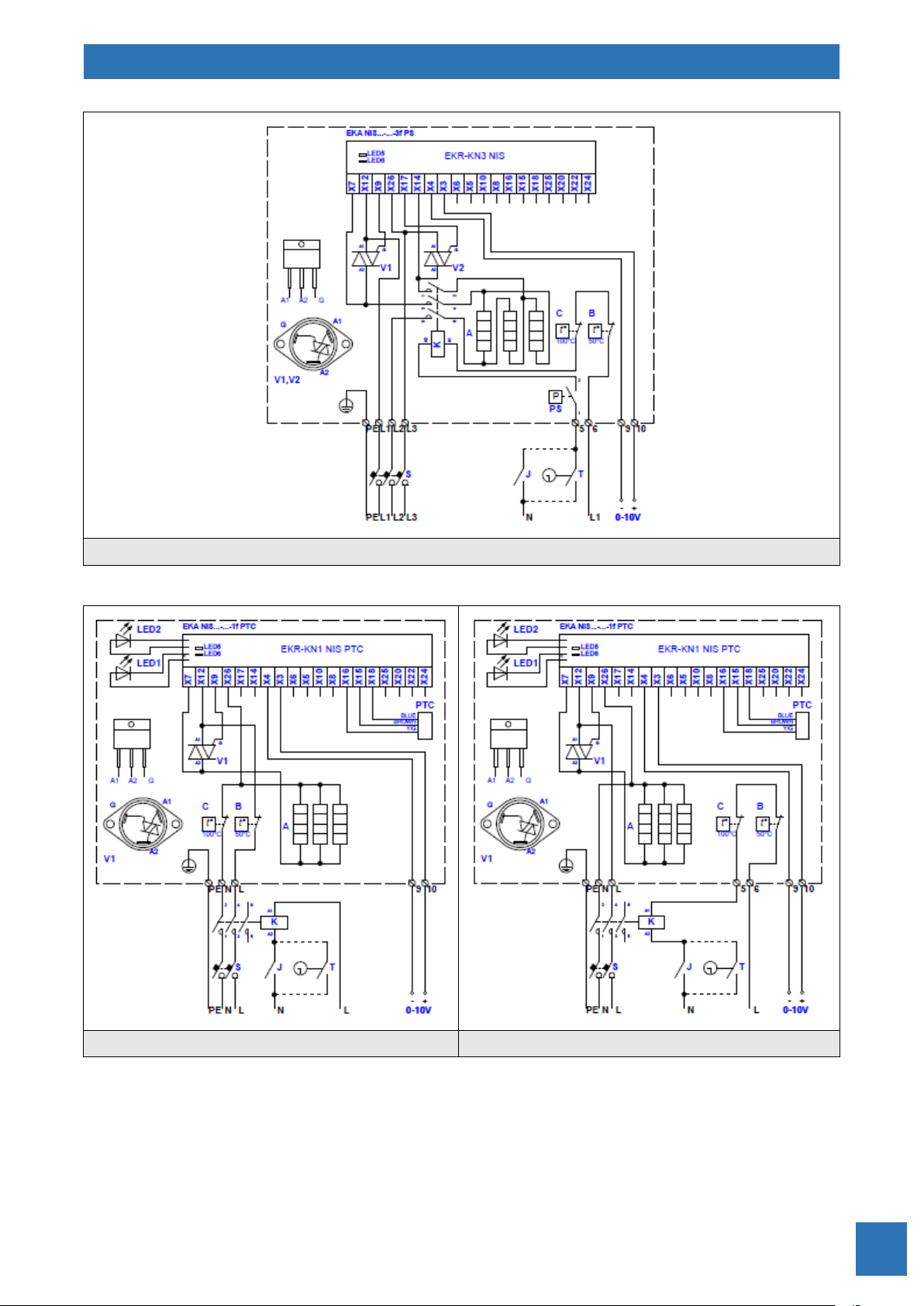
S – Automatic circuit breaker
J – Switch
T – Timer
EKR-KN… – PCB of temperature controller
V1, V2 – Triacs
A – Heating elements
B – Overheat thermostat with automatic reset
C – Overheat thermostat with manual reset
K – Contactor (relay)
PTC – Sensor for minimum air velocity detection
PS – Differential pressure switch for air flow detection
TJ-K10K – Supply air temperature sensor
TR NTC10 – Room temperature sensor panel
TR5K NTC10 – Room temperature sensor panel with remote setpoint knob
TR5K – External remote setpoint knob panel
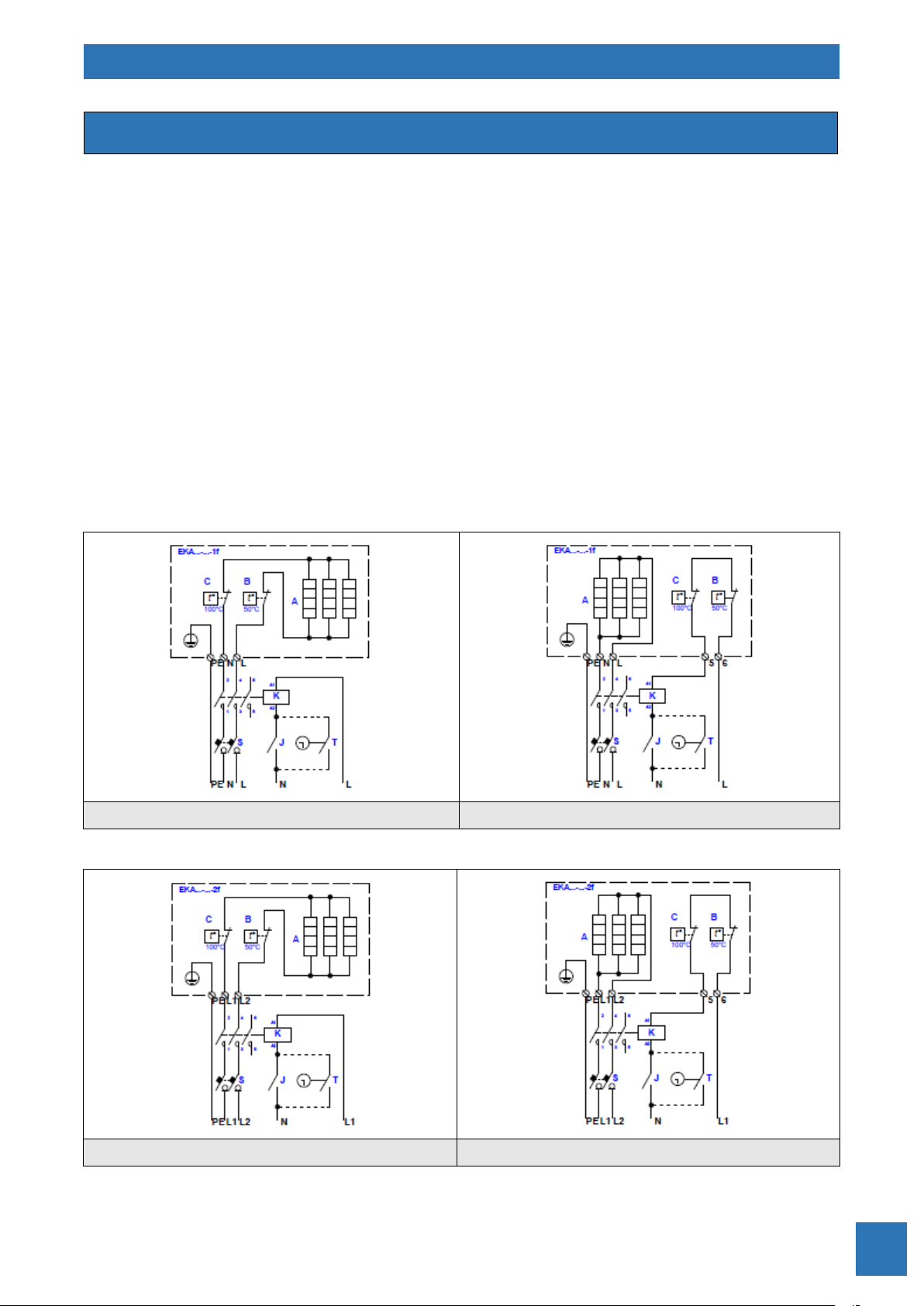
≤ 3,6 Kw
> 3,6 kW
Fig. 13. Electrical wiring diagrams of single phase 230V heater EKA…-…-1f
≤ 6 kW
> 6 kW
Fig. 14. Electrical wiring diagrams of 2-phase 400V heater EKA…-…-2f
Electrical wiring diagrams
ELECTRICAL CIRCULAR DUCT HEATERS
EKA
21
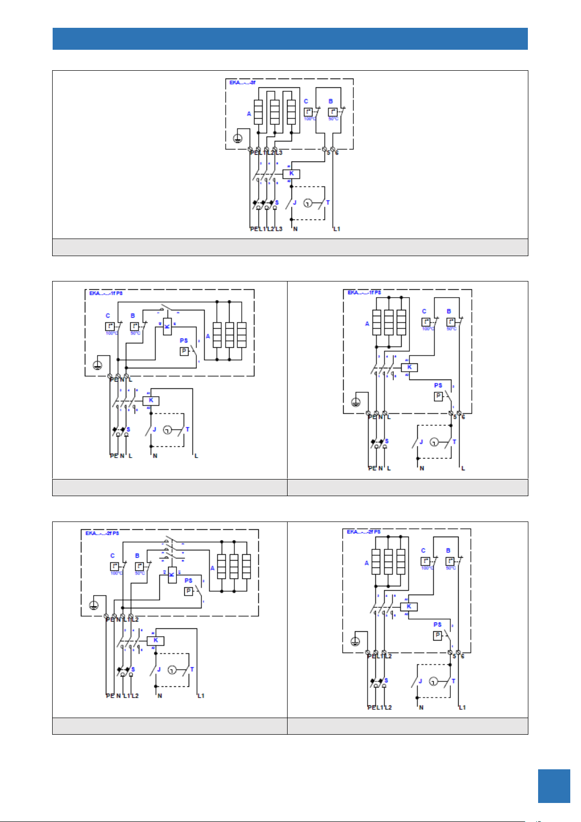
Fig. 15. Electrical wiring diagram of 3-phase 400V heater EKA…-…-3f
≤ 3,6 kW
> 3,6 kW
Fig. 16. Electrical wiring diagrams of single phase 230V heater EKA…-…-1f PS
≤ 6 kW
> 6 kW
Fig. 17. Electrical wiring diagrams of 2-phase 400V heater EKA…-…-2f PS

ELECTRICAL CIRCULAR DUCT HEATERS
EKA
22
Fig. 18. Electrical wiring diagram of 3-phase 400V heater EKA…-…-3f PS
≤ 3,6 kW
> 3,6 kW
Fig. 19. Electrical wiring diagrams of single phase 230V heater EKA NV…-…-1f

ELECTRICAL CIRCULAR DUCT HEATERS
EKA
23
≤ 6 kW
> 6 kW
Fig. 20. Electrical wiring diagrams of 2-phase 400V heater EKA NV…-…-2f
Fig. 21. Electrical wiring diagram of 3-phase 400V heater EKA NV…-…-3f

ELECTRICAL CIRCULAR DUCT HEATERS
EKA
24
≤ 3,6 kW
> 3,6 kW
Fig. 22. Electrical wiring diagrams of single phase 230V heater EKA NV…-…-1f PS
≤ 6 kW
> 6 kW
Fig. 23. Electrical wiring diagrams of 2-phase 400V heater EKA NV…-…-2f PS

ELECTRICAL CIRCULAR DUCT HEATERS
EKA
25
Fig. 24. Electrical wiring diagram of 3-phase 400V heater EKA NV…-…-3f PS
≤ 3,6 kW
> 3,6 kW
Fig. 25. Electrical wiring diagrams of single phase 230V heater EKA NV…-…-1f PTC

ELECTRICAL CIRCULAR DUCT HEATERS
EKA
26
≤ 6 kW
> 6 kW
Fig. 26. Electrical wiring diagrams of 2-phase 400V heater EKA NV…-…-2f PTC
Fig. 27. Electrical wiring diagram of 3-phase 400V heater EKA NV…-…-3f PTC
ELECTRICAL CIRCULAR DUCT HEATERS
EKA
27
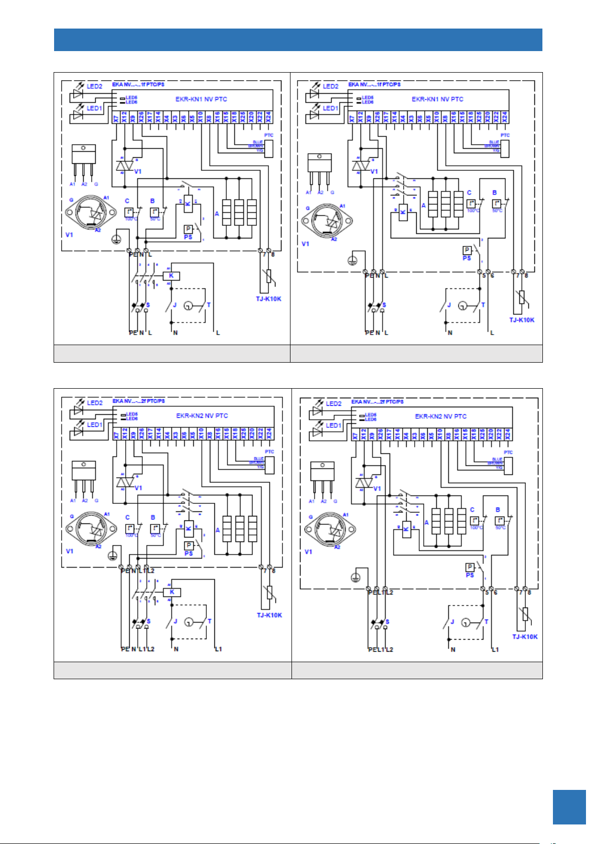
≤ 3,6 kW
> 3,6 kW
Fig. 28. Electrical wiring diagrams of single phase 230V heater EKA NV…-…-1f PTC/PS
≤ 6 kW
> 6 kW
Fig. 29. Electrical wiring diagrams of 2-phase 400V heater EKA NV…-…-2f PTC/PS

ELECTRICAL CIRCULAR DUCT HEATERS
EKA
28
Fig. 30. Electrical wiring diagram of 3-phase 400V heater EKA NV…-…-3f PTC/PS
Fig. 31. Electrical wiring diagram of single phase 230V heater EKA NV…-…-1f PTC/K

ELECTRICAL CIRCULAR DUCT HEATERS
EKA
29
Fig. 32. Electrical wiring diagram of 2-phase 400V heater EKA NV…-…-2f PTC/K
Fig. 33. Electrical wiring diagram of 3-phase 400V heater EKA NV…-…-3f PTC/K

ELECTRICAL CIRCULAR DUCT HEATERS
EKA
30
≤ 3,6 kW
> 3,6 Kw
Fig. 34. Electrical wiring diagrams of single phase 230V heater EKA NV…-…-1f PH
≤ 6 kW
> 6 kW
Fig. 35. Electrical wiring diagrams of 2-phase 400V heater EKA NV…-…-2f PH
ELECTRICAL CIRCULAR DUCT HEATERS
EKA
31
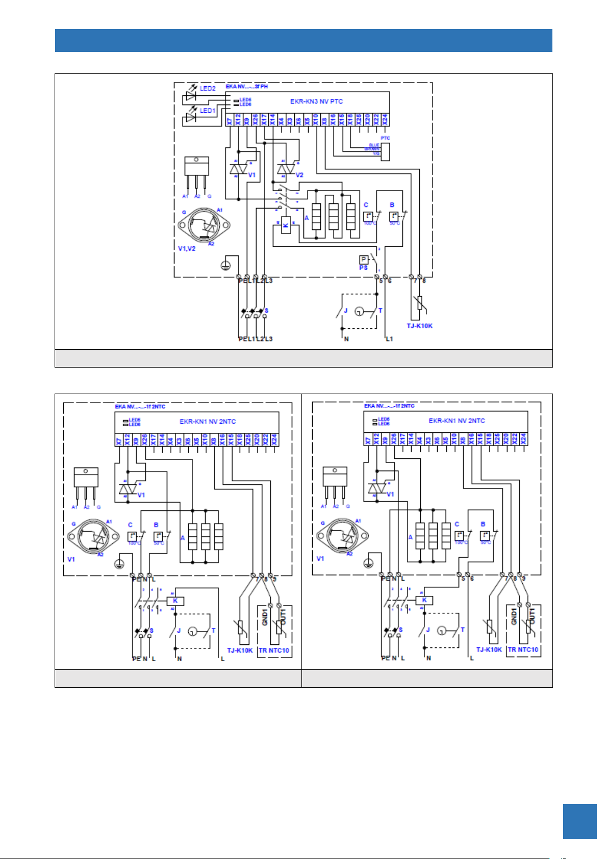
Fig. 36. Electrical wiring diagram of 3-phase 400V heater EKA NV…-…-3f PH
≤ 3,6 kW
> 3,6 Kw
Fig. 37. Electrical wiring diagrams of single phase 230V heater EKA NV…-…-1f 2NTC

ELECTRICAL CIRCULAR DUCT HEATERS
EKA
32
≤ 6 kW
> 6 kW
Fig. 38. Electrical wiring diagrams of 2-phase 400V heater EKA NV…-…-2f 2NTC
Fig. 39. Electrical wiring diagram of 3-phase 400V heater EKA NV…-…-3f 2NTC

ELECTRICAL CIRCULAR DUCT HEATERS
EKA
33
≤ 3,6 kW
> 3,6 Kw
Fig. 40. Electrical wiring diagrams of single phase 230V heater EKA NV…-…-1f PTC/2NTC
≤ 6 kW
> 6 kW
Fig. 41. Electrical wiring diagrams of 2-phase 400V heater EKA NV…-…-2f PTC/2NTC

ELECTRICAL CIRCULAR DUCT HEATERS
EKA
34
Fig. 42. Electrical wiring diagram of 3-phase 400V heater EKA NV…-…-3f PTC/2NTC
≤ 3,6 kW
> 3,6 Kw
Fig. 43. Electrical wiring diagrams of single phase 230V heater EKA NI…-…-1f

ELECTRICAL CIRCULAR DUCT HEATERS
EKA
35
≤ 6 kW
> 6 kW
Fig. 44. Electrical wiring diagrams of 2-phase 400V heater EKA NI…-…-2f
Fig. 45. Electrical wiring diagram of 3-phase 400V heater EKA NI…-…-3f

ELECTRICAL CIRCULAR DUCT HEATERS
EKA
36
≤ 3,6 kW
> 3,6 Kw
Fig. 46. Electrical wiring diagrams of single phase 230V heater EKA NI…-…-1f PS
≤ 6 kW
> 6 Kw
Fig. 47. Electrical wiring diagrams of 2-phase 400V heater EKA NI…-…-2f PS

ELECTRICAL CIRCULAR DUCT HEATERS
EKA
37
Fig. 48. Electrical wiring diagram of 3-phase 400V heater EKA NI…-…-3f PS
≤ 3,6 kW
> 3,6 Kw
Fig. 49. Electrical wiring diagrams of single phase 230V heater EKA NI…-…-1f PTC

ELECTRICAL CIRCULAR DUCT HEATERS
EKA
38
≤ 6 kW
> 6 Kw
Fig. 50. Electrical wiring diagrams of 2-phase 400V heater EKA NI…-…-2f PTC
Fig. 51. Electrical wiring diagram of 3-phase 400V heater EKA NI…-…-3f PTC

ELECTRICAL CIRCULAR DUCT HEATERS
EKA
39
≤ 3,6 kW
> 3,6 Kw
Fig. 52. Electrical wiring diagrams of single phase 230V heater EKA NI…-…-1f PTC/PS
≤ 6 kW
> 6 Kw
Fig. 53. Electrical wiring diagrams of 2-phase 400V heater EKA NI…-…-2f PTC/PS

ELECTRICAL CIRCULAR DUCT HEATERS
EKA
40
Fig. 54. Electrical wiring diagram of 3-phase 400V heater EKA NI…-…-3f PTC/PS
Fig. 55. Electrical wiring diagram of single phase 230V heater EKA NI…-…-1f PTC/K

ELECTRICAL CIRCULAR DUCT HEATERS
EKA
41
Fig. 56. Electrical wiring diagram of 2-phase 400V heater EKA NI…-…-2f PTC/K
Fig. 57. Electrical wiring diagram of 3-phase 400V heater EKA NI…-…-3f PTC/K

ELECTRICAL CIRCULAR DUCT HEATERS
EKA
42
≤ 3,6 kW
> 3,6 Kw
Fig. 58. Electrical wiring diagrams of single phase 230V heater EKA NI…-…-1f PH
≤ 6 kW
> 6 Kw
Fig. 59. Electrical wiring diagrams of 2-phase 400V heater EKA NI…-…-2f PH

ELECTRICAL CIRCULAR DUCT HEATERS
EKA
43
Fig. 60. Electrical wiring diagram of 3-phase 400V heater EKA NI…-…-3f PH
≤ 3,6 kW
> 3,6 Kw
Fig. 61. Electrical wiring diagrams of single phase 230V heater EKA NI…-…-1f 2NTC
ELECTRICAL CIRCULAR DUCT HEATERS
EKA
44
≤ 6 kW
> 6 Kw
Fig. 62. Electrical wiring diagrams of 2-phase 400V heater EKA NI…-…-2f 2NTC
Fig. 63. Electrical wiring diagram of 3-phase 400V heater EKA NI…-…-3f 2NTC
ELECTRICAL CIRCULAR DUCT HEATERS
EKA
45
≤ 3,6 kW
> 3,6 Kw
Fig. 64. Electrical wiring diagrams of single phase 230V heater EKA NI…-…-1f PTC/2NTC
≤ 6 kW
> 6 Kw
Fig. 65. Electrical wiring diagrams of 2-phase 400V heater EKA NI…-…-2f PTC/2NTC
ELECTRICAL CIRCULAR DUCT HEATERS
EKA
46
Fig. 66. Electrical wiring diagram of 3-phase 400V heater EKA NI…-…-3f PTC/2NTC
≤ 3,6 kW
> 3,6 Kw
Fig. 67. Electrical wiring diagrams of single phase 230V heater EKA NIS…-…-1f

ELECTRICAL CIRCULAR DUCT HEATERS
EKA
47
≤ 6 kW
> 6 Kw
Fig. 68. Electrical wiring diagrams of 2-phase 400V heater EKA NIS…-…-2f
Fig. 69. Electrical wiring diagram of 3-phase 400V heater EKA NIS…-…-3f

ELECTRICAL CIRCULAR DUCT HEATERS
EKA
48
≤ 3,6 kW
> 3,6 Kw
Fig. 70. Electrical wiring diagrams of single phase 230V heater EKA NIS…-…-1f PS
≤ 6 kW
> 6 Kw
Fig. 71. Electrical wiring diagrams of 2-phase 400V heater EKA NIS…-…-2f PS
ELECTRICAL CIRCULAR DUCT HEATERS
EKA
49
Fig. 72. Electrical wiring diagram of 3-phase 400V heater EKA NIS…-…-3f PS
≤ 3,6 kW
> 3,6 Kw
Fig. 73. Electrical wiring diagrams of single phase 230V heater EKA NIS…-…-1f PTC

ELECTRICAL CIRCULAR DUCT HEATERS
EKA
50
≤ 6 kW
> 6 Kw
Fig. 74. Electrical wiring diagrams of 2-phase 400V heater EKA NIS…-…-2f PTC
Fig. 75. Electrical wiring diagram of 3-phase 400V heater EKA NIS…-…-3f PTC

ELECTRICAL CIRCULAR DUCT HEATERS
EKA
51
≤ 3,6 kW
> 3,6 Kw
Fig. 76. Electrical wiring diagrams of single phase 230V heater EKA NIS…-…-1f PTC/PS
≤ 6 kW
> 6 Kw
Fig. 77. Electrical wiring diagrams of 2-phase 400V heater EKA NIS…-…-2f PTC/PS

ELECTRICAL CIRCULAR DUCT HEATERS
EKA
52
Fig. 78. Electrical wiring diagram of 3-phase 400V heater EKA NIS…-…-3f PTC/PS
Fig. 79. Electrical wiring diagram of single phase 230V heater EKA NIS…-…-1f PTC/K

ELECTRICAL CIRCULAR DUCT HEATERS
EKA
53
Fig. 80. Electrical wiring diagram of 2-phase 400V heater EKA NIS…-…-2f PTC/K
Fig. 81. Electrical wiring diagram of 3-phase 400V heater EKA NIS…-…-3f PTC/K

ELECTRICAL CIRCULAR DUCT HEATERS
EKA
54
≤ 3,6 kW
> 3,6 Kw
Fig. 82. Electrical wiring diagrams of single phase 230V heater EKA NIS…-…-1f PH
≤ 6 kW
> 6 Kw
Fig. 83. Electrical wiring diagrams of 2-phase 400V heater EKA NIS…-…-2f PH

ELECTRICAL CIRCULAR DUCT HEATERS
EKA
55
Fig. 84. Electrical wiring diagram of 3-phase 400V heater EKA NIS…-…-3f PH
≤ 3 kW
Fig. 85. Electrical wiring diagram of single phase 230V heater EKA ESKM…-…-1f

ELECTRICAL CIRCULAR DUCT HEATERS
EKA
56
≤ 6 kW
Fig. 86. Electrical wiring diagram of 2-phase 400V heater EKA ESKM…-…-2f
≤ 15 kW
Fig. 87. Electrical wiring diagram of 3-phase 400V heater EKA ESKM…-…-3f

ELECTRICAL CIRCULAR DUCT HEATERS
EKA
57
Fill in this warranty information form and keep this page for future reference or when
warranty service may be required.
Model name
EKA ..... .....-.....-.....f .....
Warranty period
Date of invoice
Customer info
Name (company)
Address
Contact info
Retailer info
Name (company)
Address
Contact info
Fault description
The product warranty covers product malfunctions, under normal operating conditions for 24
months from the date of manufacturer’s invoice. Please note that the product warranty terms may
vary depending on purchase or installation contracts.
During the product warranty period, warranty service (free of charge) is provided for product
malfunctions caused under normal operating conditions. For warranty service, contact an official
“Ventmatika“ dealer. Any manipulation of the appliance by personnel not appointed by
“Ventmatika“ will cancel the guarantee. “Ventmatika“ reserves the right to modify the product
without prior notice.
Product warranty

ELECTRICAL CIRCULAR DUCT HEATERS
EKA
58
Notes
 Loading...