

Page 1
Water Wash Control panels
C O N T R O L P A N E L S
I n s t a l l a t i o n ,
O p e r a t i o n ,
M a i n t e n a n c e
a n d S e r v i c e
I n s t r u c t i o n s
Enodis
Page 2

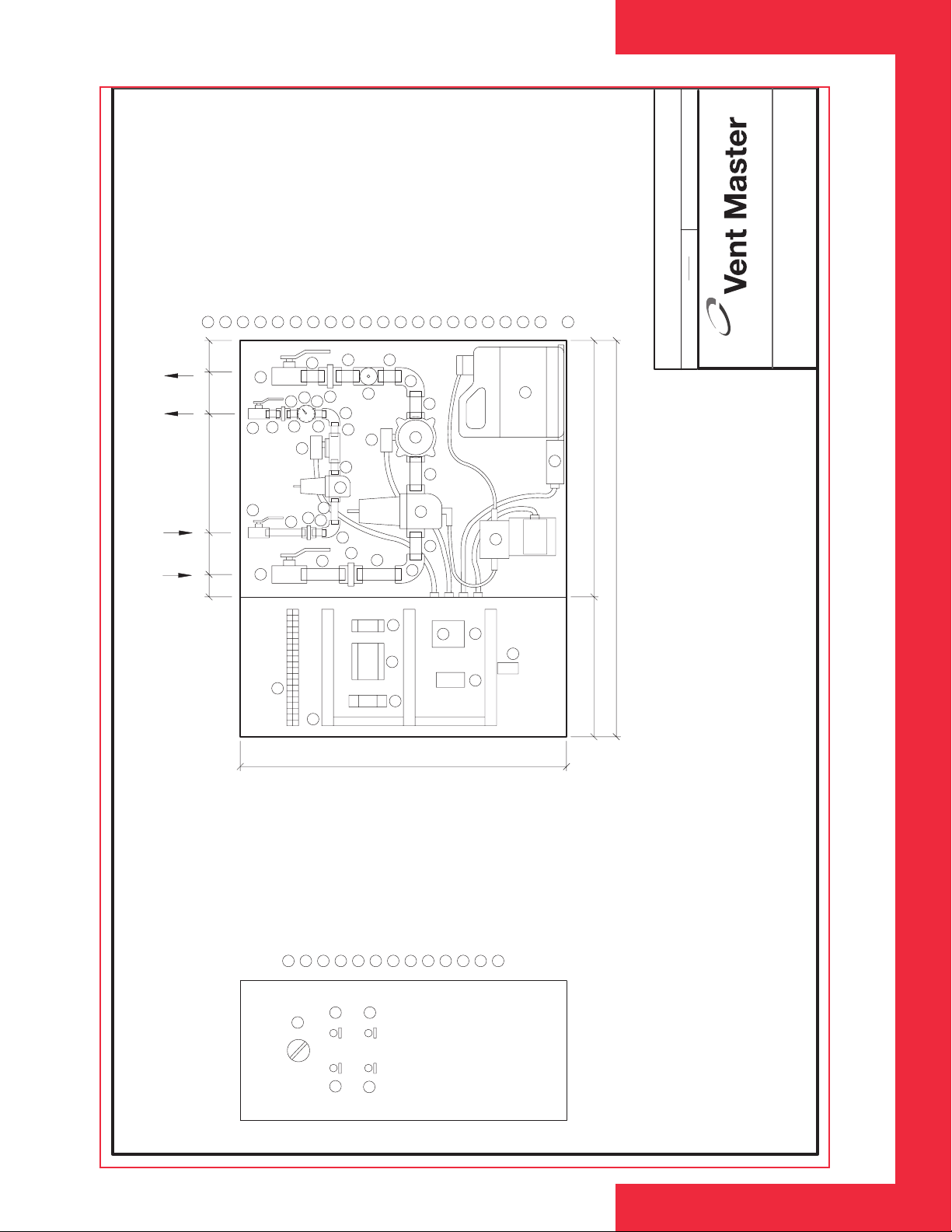
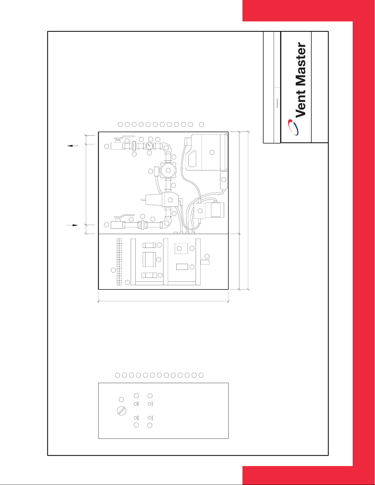
C O N T R O L P A N E L C O M P O N E N T
F U N C T I O N S
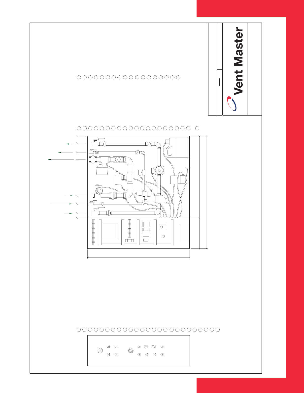
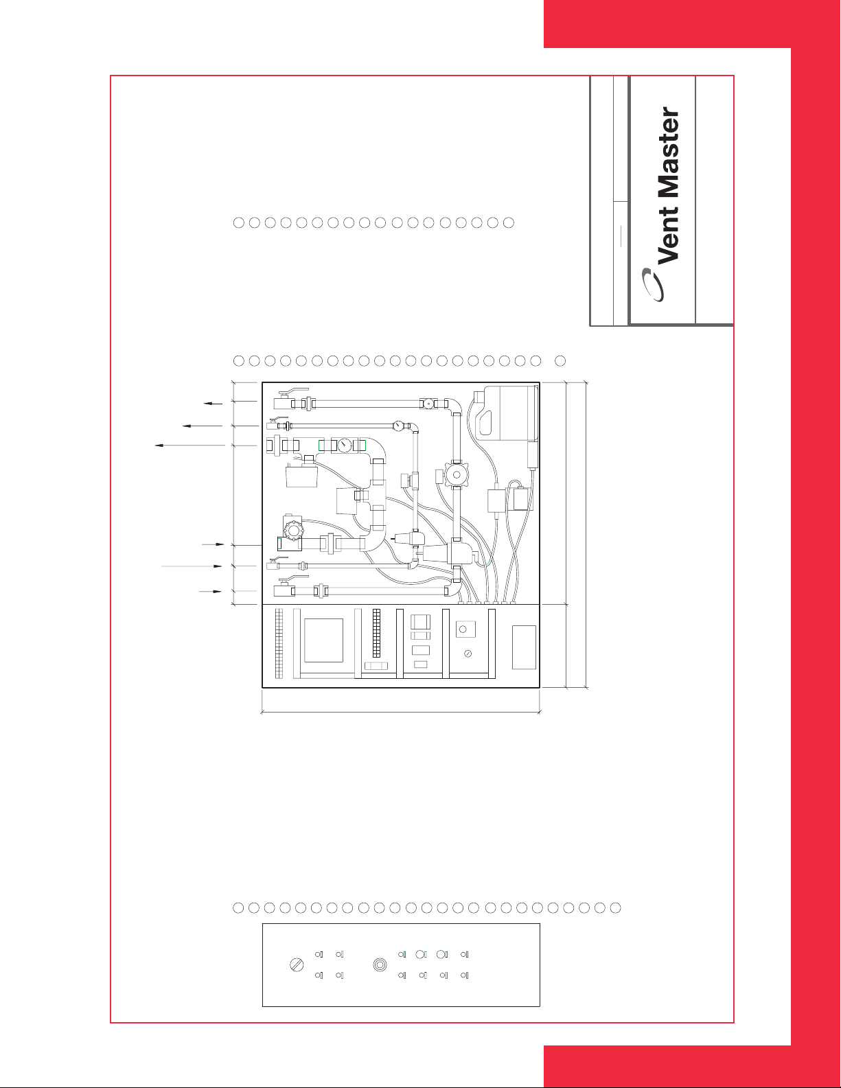
Water Shut Off Valves: There are two water shut-off valves on both the hot
and cold water* lines, so that the components in both hot and cold water
lines can be isolated for easy removal.
Pressure Reducing Valves: These valves are located in the hot and cold
water* lines to reduce the operating pressure to 25 PSI (172 kPa).
Solenoid Valves: There is a solenoid valve in both the hot and cold water*
lines to automatically control the water flow.
Detergent Pump: This pump is used to inject a controlled amount of
detergent into the hot water line when in wash mode.
Timer Relay: This relay energizes both the hot water solenoid and the
detergent pump for the wash cycle; it determines the length of the wash
cycle.
Fuse Block & Terminal Strip: To provide a 5 amp fuse to protect the
electrical components in the control panel.
Selector Switch:
a) To activate the exhaust fan and cold water* spray. for the Cyclo Maze
ventilation, turn switch to the ‘RUN’ position.
V E N T I L A T O R
C O M P O N E N T
F U N C T I O N S
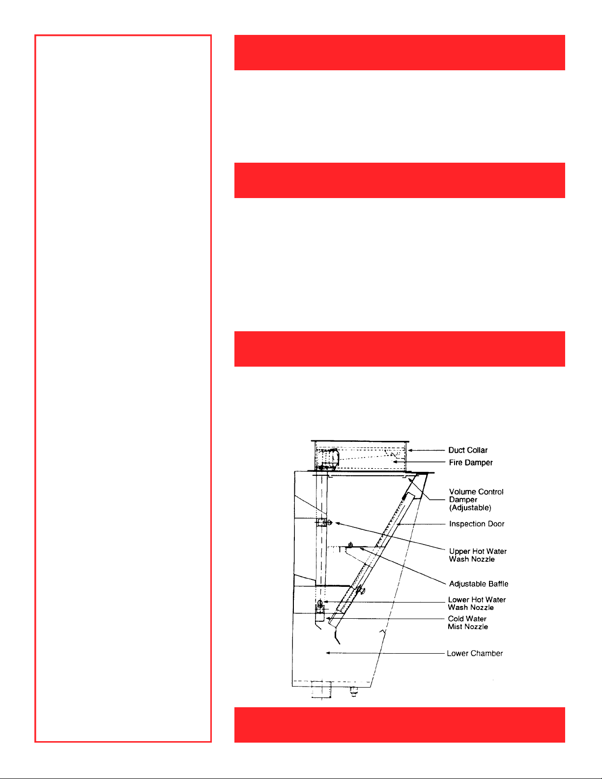
Adjustable Baffle and Removable
Access Door: To allow CFM varia-
tions over the length of the ventilator.
They are also removable to provide
access to the chamber.
Water Spray Nozzles: There are
both hot and cold water* spray
nozzles.
Fire Damper: To prevent fire from
going up the duct; the damper is held
open by one 286°F (141°C) fusible
link.
Volume Control Damper: A n
a d j u s t a bl e, hori zontal bl a d e - t y p e
damper is provided at the exhaust
collar allowing for velocity changes in
the field (after hood installations).
b) To activate the hot water wash cycle for the Cyclo Maze ventilator, turn
switch to the “WASH‘ position.
Cold Water Pressure Gauge: This gauge is used to check the cold water*
pressure on the outlet side of the pressure reducing valve. Should read 25
PSI (138 kPa) while in operation.
Plug-Hot Water Line: This plug can be removed and a pressure gauge or
thermometer screwed into the hole for field temperature and pressure
reading.
Cold Water* and Hot Water Strainers: The strainers located in the PRV
valve are used to strain out dirt from the water flow and to protect the
solenoid valves and water nozzles from plugging up.
Detergent Pump CheckValves: This valve stops the detergent in the pump
and tube from draining back down into the detergent tank when the pump is
not in operation, eliminating the need to continually prime the pump.
2
*H4-25 models are not provided with
the cold water feature.
Page 3
I N S TA L L A T I O N I N S T R U C T I O N S
Models: HC4-25 and H4-25
S T A R T U P A N D
O P E R A T I N G
I N S T R U C T I O N
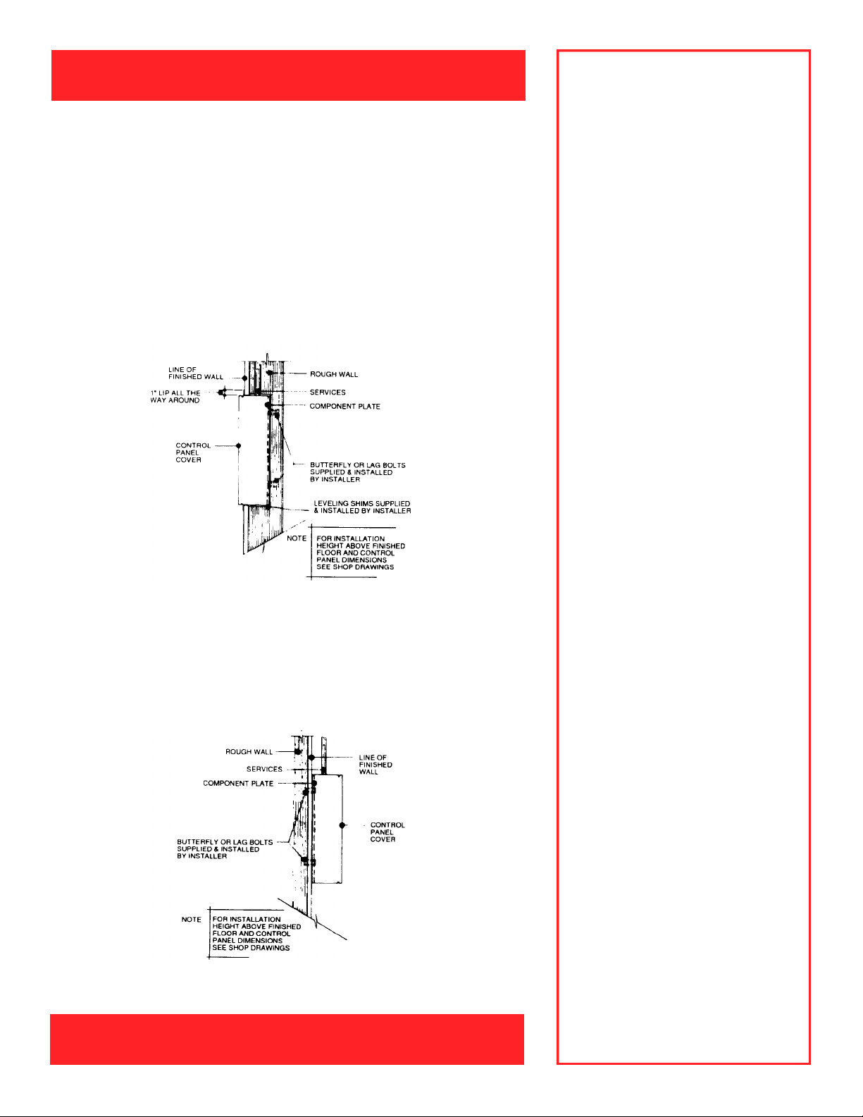
Location of control panel is determined by the kitchen equipment contractor.
The recommended mounting height above the finished floor and type
(recessed suffix ‘R’ or surface suffix ‘S’ mount) is indicated on the ventilator
shop drawing.
RECESSED CONTROL PANEL
Recessed mounted models.The panel can be shipped early to allow cabinet
to be built into wall. Fastening as per surface mount units.
See Drawing 1.
Drawing 1
Sequence of Operation
1.Turn selector switch to ‘RUN’
- Exhaust fan energized
- Make-up air fan energized
- Cold water turns on
(HC4-25 only)
2.Turn selector switch to ‘WASH’
- Exhaust fan de-energized
- Make-up air fan de-energized
- Cold water turns off
(HC4-25 only)
- Wash begins after 60 second
delay
- Wash ends after preset time
3. Fire condition
- Switch at fire panel closes
- Exhaust fan stops
- Make-up air fan stops
- Cold water turns off (HC4-25
only)
- Hot water turns on
- Dry contacts at 15 and 16 close
SURFACE MOUNT CONTROL PANEL
Surface mounted models are shipped as a complete unit.The installer must
drill holes in the back of the cabinet and component plate to suit wall
structure and securely fasten panel to wall with lag or butterfly bolts.
See Drawing 2.
Drawing 2
Fire condition sequence of operation
to be confirmed to apply to local
codes.
3
Page 4
A U T O M A T I C
C L E A N I N G
P R E S S U R E R E D U C I N G V A L V E
During the day grease accumulates in
the interior chamber of the extractor
unit in the water wash hood, therefore, a cleaning cycle is provided to
properly clean all interior surfaces.
When the selector switch is turned to
the ‘WASH’ position at the control
panel, the exhaust fan and cold water
solenoid* are de-energized.After a 60
second delay (to allow the exhaust
fan wheel to stop rotating), a pre-set
wash timer energizes the hot water
solenoid and detergent pump system
for a short cleaning cycle. The
hot water and detergent mixture
is sprayed through a series of
s t rategically placed nozzles to
scour the interior of the unit.
CAUTION: If the cleaning cycle is not
maintained, accumulated grease can
constitute a fire hazard and impair the
overall performance of the unit(s) and
nozzles.
Hot and cold* water supply to the panel requires a minimum pressure of 40
PSI (276 kPa). Hot water requires a minimum temperature of 140°F (60°C).
The pressure reducing valves are factory set for an outlet pressure of 25 PSI
(172 kPa).The resulting pressure at the hood nozzle should be 20 PSI (138
kPa).If necessary, adjust the factory preset pressure reducing valve until the
required pressure is obtained.
W A S H C Y C L E
Turn selector switch to the ‘WASH’position which will initiate the wash cycle
and shut down fan and cold water spray. Check ventilator to see if hot water
nozzles are functioning properly. After wash cycle has been completed,
remove access door(s) and visually check to see if upper wash nozzles have
a uniform spray pattern by observing water droplets on surface of upper
chamber.
Remove and clean nozzle orifice if not spraying properly. Remove strainer
enclosure on the pressure reducing valve in hot water line.Inspect and clean
if necessary.
W A S H T I M E R
N OT E : After control panel and
ventilator units have been installed,
all hot and cold water* and drain
connections made and electric
connections completed and system
has received factory authorized startup, the system is ready to be put into
operation.Refer to start-up check list.
R U N C Y C L E
Tu rn selector switch to the ‘ RU N ’
position, exhaust fan will start and
cold water solenoid* will open. Check
ventilators to see if cold water spray is
functioning properl y. Place hand
through slot opening in front of ventilator. There should be an even flat,
overlapping spray across the entire
length of the ventilator.If nozzles are
not spraying properly, remove and
clean the ori f i c e. R e m ove access
door in order to reach cold water
n o z z l e. (See drawing 3). R e m ove
strainer (enclosed on the pressure
reducing va l ve in cold water line.
Inspect and clean, if necessary.
*H4-25 models are not provided with
the cold water feature.
A wash cycle of two minutes is preset at the factory. Under extreme
conditions such as charcoal broiling or if hot water supply is located some
distance from ventilators, it may be necessary to increase time cycle. It is
suggested that this be done in one minute increments until proper time cycle
is established.
Drawing 3
CYCLO MAZE WASH CHAMBER
4
Page 5

P R I M I N G
D E T E R G E N T P U M P
C H E C K L I S T P R I O R T O S T A R T - U P
1. Loosen the plastic nut at the outlet
of the detergent pump.
2. Cycle the detergent pump by
t u rning the wing nut in a clock w i s e
d i r e c t i o n .
3. Continue with step 2 until the
detergent flows from the loosened
nut, then tighten the nut.
D R A I N L I N E S
Ensure system is put through wash
cycle at least daily with hot water and
detergent. If detergent is not used or
wash cycle ignored, drain line may
become clogged.
NOTE: Before starting the control panel, the following should be checked:
Electrical
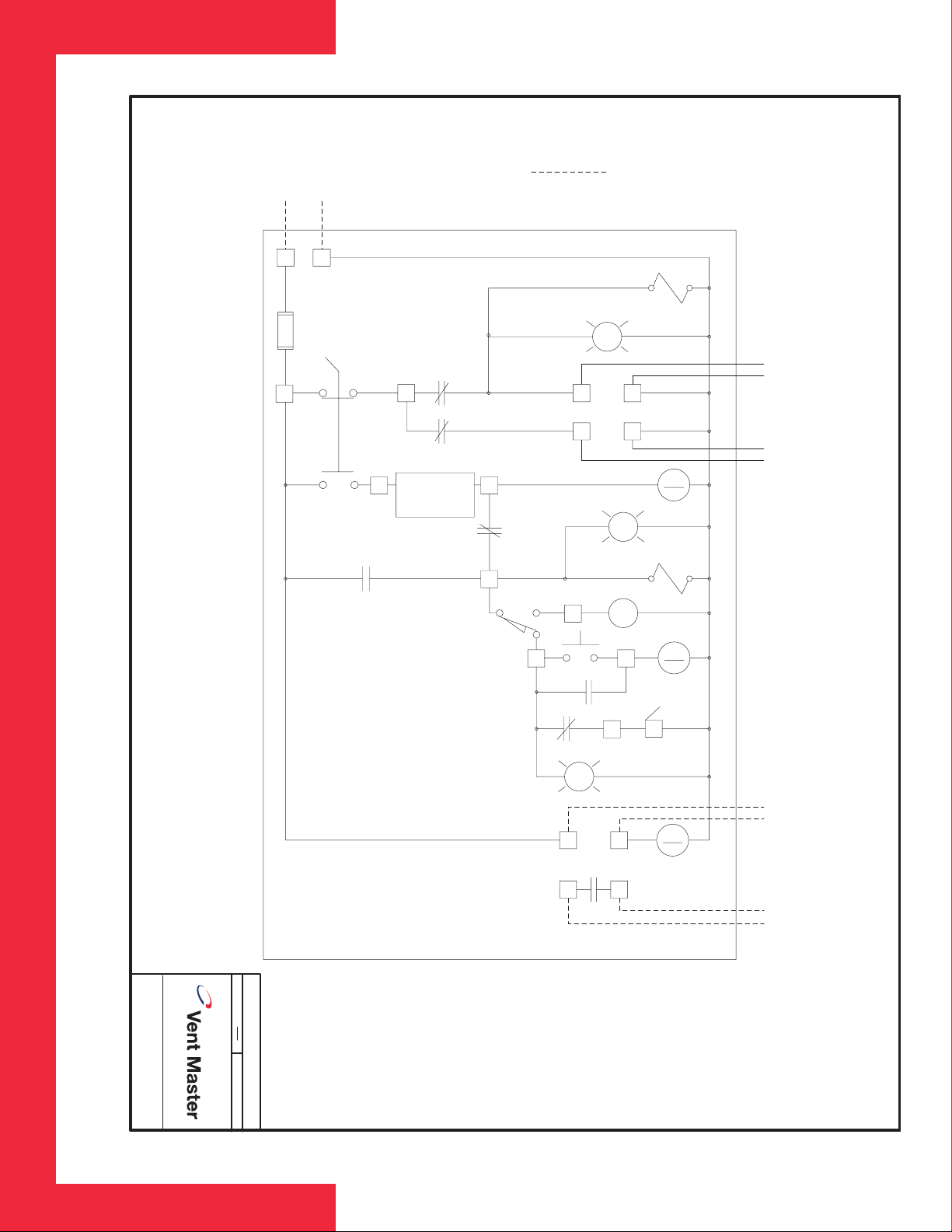
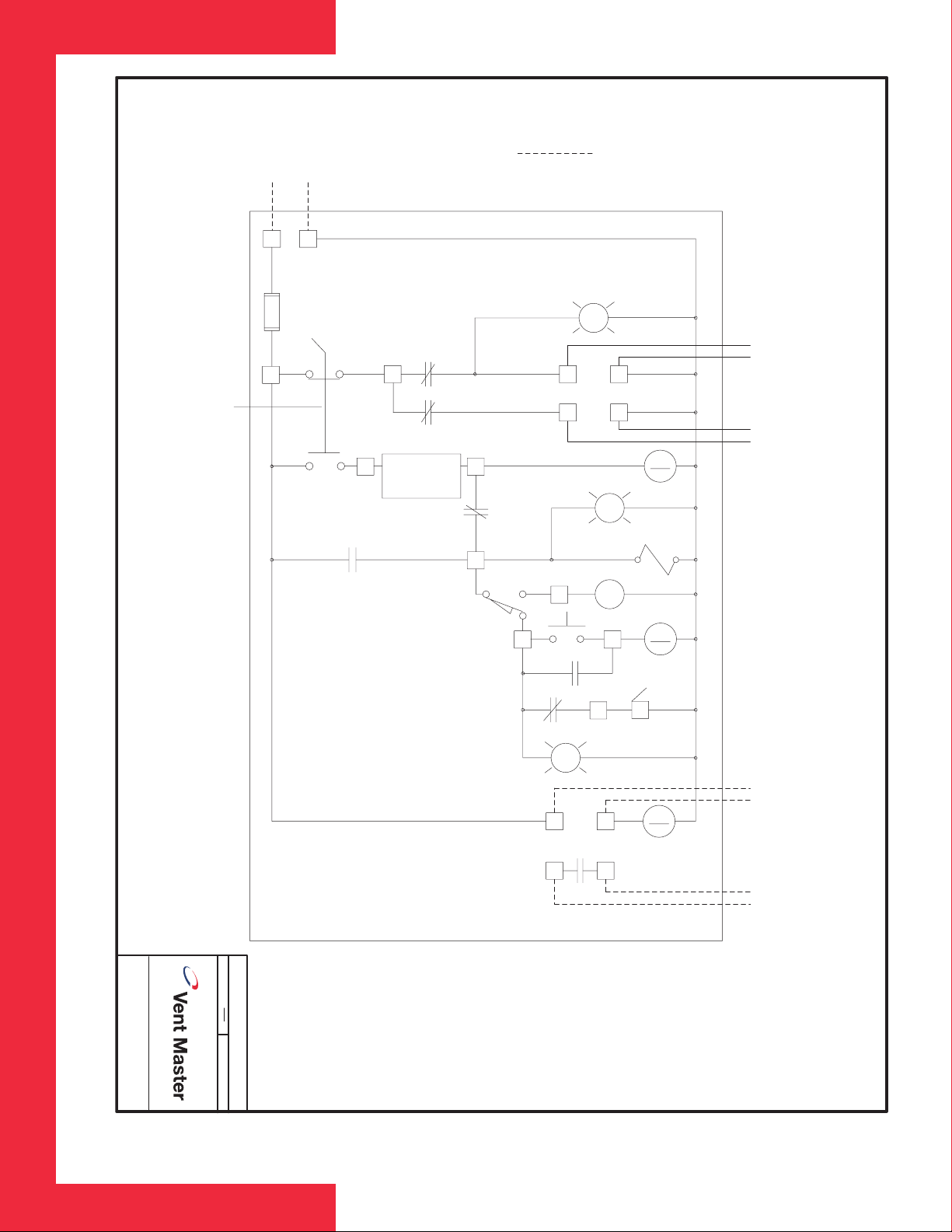
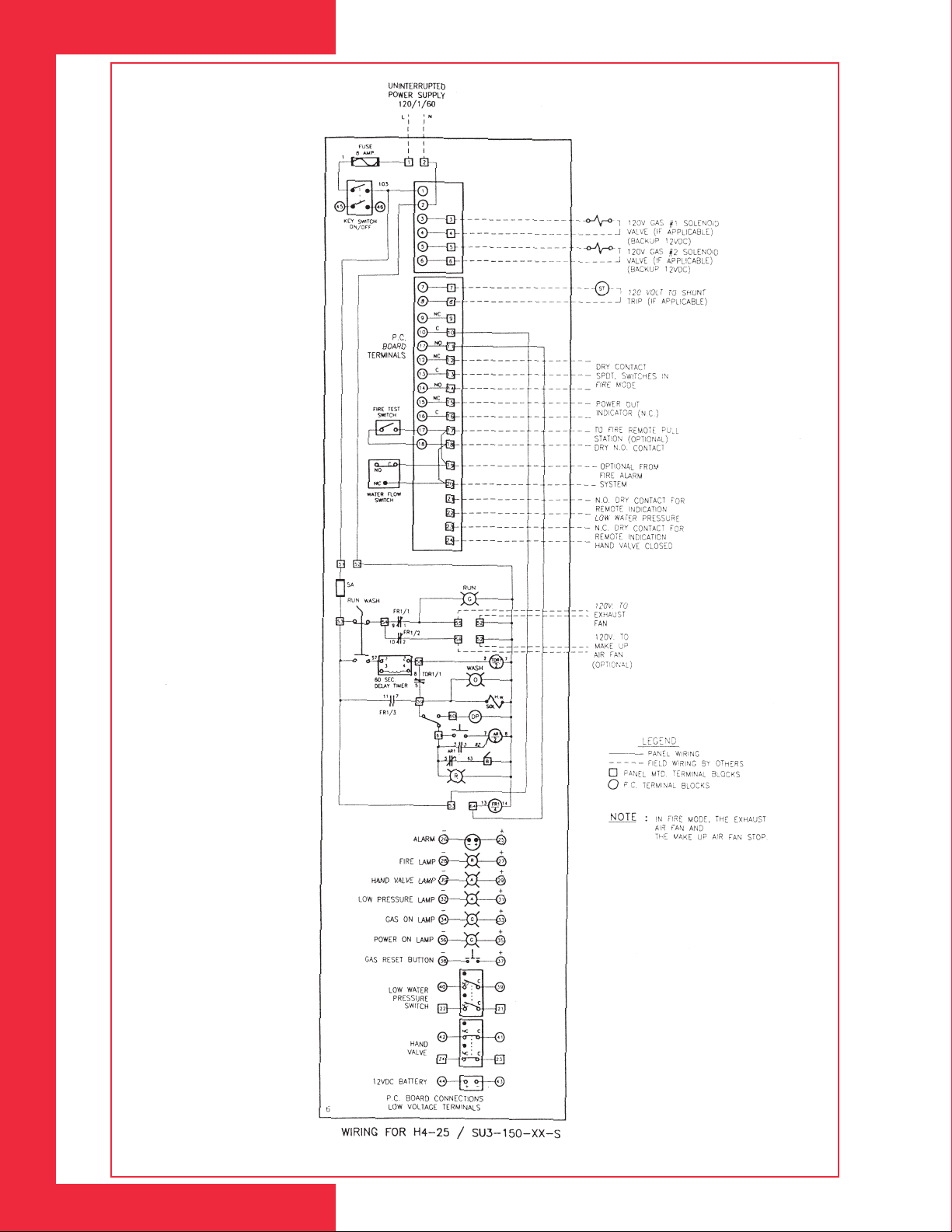
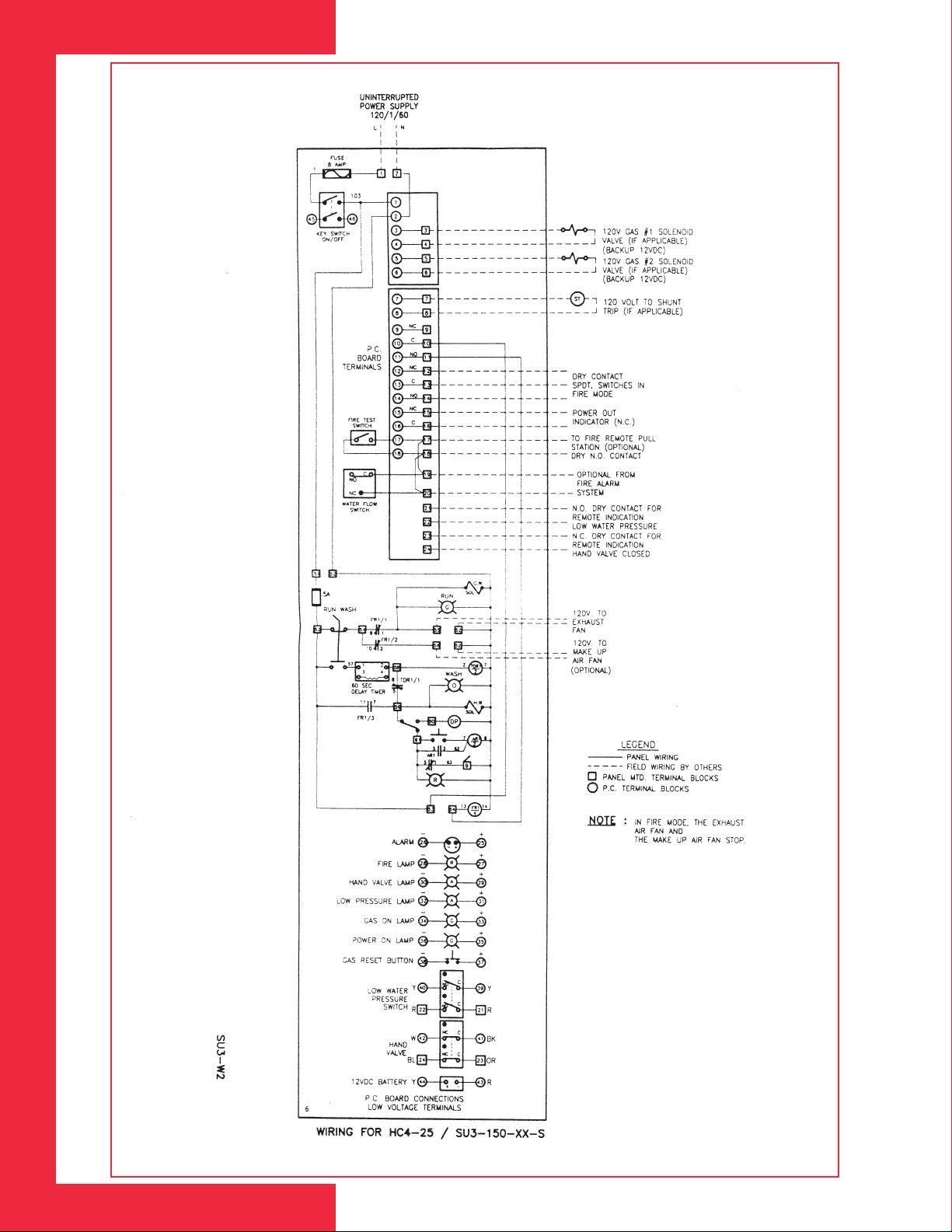
1. Connection to 120V, 60 cycle, 1 phase from main supply to the control
panel, terminals #1 and #2.
2. Connection of 120V, 60 cycle, 1 phase from control panel, terminals #5
and #2, to exhaust fan magnetic starter coil.
3.Timer set for 2 minutes on HC4 models and 4 minutes on H4 models.
NOTE: Control panel wiring schematic located within control panel. Caution
for proper system operation, the exhaust fan must be controlled by the water
wash control panel.
Plumbing
1. Cold water (from supply) to the control panel.Note, not applicable to H4
models.
2. Hot water (from supply) to the control panel.
3. Connections for the above from the control panel to the ventilator(s).
4. Drain line and connections from the ventilator(s) to the drain.
5. Supply lines properly flushed before connection to control panel.
6. Strainers clean and free of foreign material.
7. Nozzles in hood properly oriented.
8. Nozzle orifice free of foreign material.
9. G-WIZ detergent bottle in place filled with detergent, complete with foot
valve inserted in bottle. Detergent bottle must be seated firmly on low
liquid tray provided.
10. Detergent pump connected properly, primed and set for proper amount
of detergent.
11.Ventilator free of foreign material that would clog drain.
12. Cold water shut-off valve on and a setting of 25 PSI (172 kPa) on dial.
Note, not applicable to H4 models.
13. Hot water shut-off valve on and flow pressure setting of approximately 25
PSI (172 kPa) portable gauge check.
Other
1. Slot intake in hood open to proper width.
2. Exhaust duct connected properly.
3. Upper (wash) chamber doors properly closed. Note, applicable to Cyclo
Wash series only.
4. Is hood hanging level and plumb?
5. Is fire damper fully open?
6. Is air volume control damper secured?
5
Page 6

S T A R T - U P T E S T
1. Open stainless steel cover on control panel to expose plumbing.
2. Close both hot and cold water valves.
3. Turn selector switch to the ‘RUN’ position.
4. Check if ‘RUN’pilot light is on.
5. Is fan running?
6. Check velocity at slot opening (FPM). Note, refer to the ventilator shop
drawing for FPM slot velocities.
7. If within specified speed, turn hot and cold water valve on. (HC4-25
models only).
8. Adjust pressure reducing valve on cold water line to 25 PSI (172 kPa)
while water is running. (HC4-25 models only).
9. Check that all cold water nozzles are spraying properly by sliding hand
along slot area. (HC4-25 models only).
10.Turn selector switch to the ‘WASH’position.
11. Amber pilot light should come on.
12. Fan should shut off.
13. Cold water spray should shut off. Check again through slot areas. (HC4-
25 models only).
14. Insert gauge into hot water port provided. Hot water pressure gauge
should read 25 PSI (172 kPa) flow pressure while water running.
15.Visible hot water nozzles should be spraying in slot area.
16. Check detergent pump. Is it pumping detergent?
17. Is unit draining properly?
18. After wash cycle is complete, remove access panels.
19. Check upper hot water nozzles. They should still be dripping, if not,
remove nozzle and clean.
20. At end of wash cycle, did hot water shut off? All pilot lights are off.
6
Page 7

M A I N T E N A N C E
A N D C A R E
I N S T R U C T I O N
HC4-25 with cold water spray and hot
water wash cycle is 2 minutes
average.
H4-25 with hot water wash cycle only
is 4 minutes average.
N OT E : A clogged nozzle is an indicator
that line strainers (located in the PRV)
should be cleaned in control panel.
Quarterly
Clean interior and exterior of control
panel. Clean all line strainers located
in PRV valve.See Major Components
drawings for exact location.
S E R V I C E I N S T R U C T I O N
The control panel consists of water shut-off valves, water pressure reducing
valves, solenoid valves, detergent pump, relay timer, etc., as shown in Major
Components drawings.
SOLENOID
The valves are two-way normally closed, internal pilot operated solenoid
valve. The normally closed valve is closed when solenoid is de-energized
and opens when solenoid is energized.
Coil Replacement
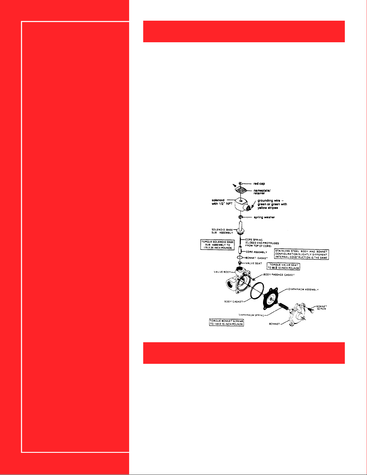
To replace the coil, turn off the electric power supply and close the water
supply shut-off valve. Refer to Drawing 4. Proceed in the following manner:
1. Disconnect coil lead wires.
2. Remove retaining cap, name plate and cover. Caution:when retaining cap
disengages, it will spring upwards.
Check detergent pump(s) for leaks or
broken fittings during a wash cycle.
ensure pump is primed and pumping.
Check solenoids for ‘click’when ‘RUN’
and ‘WASH’ switch is energized. See
Major Components drawings fo r
exact location.
3. Slip yoke containing coil, sleeves and insulating washers off the solenoid
base sub-assembly.
4. Re-assemble in reverse order of disassembly, paying careful attention to
exploded view in Drawing 4. The solenoid must be fully re-assembled as
the housing and internal parts are part of, and complete the magnetic
circuit.
5. Connect coil lead wires, open shut-off valves, turn on power and test
valve.
Valve Disassembly
1. De-pressurize valve and turn off electrical power.
2. Disassemble valve in an orderly fashion.Pay careful attention to exploded
view in Drawing 4 provided for identification and placement of parts.
3. Remove retaining cap and slip entire solenoid enclosure off the solenoid
base sub-assembly. Caution: when retaining cap disengages, it will spring
upwards.
4. Unscrew solenoid base sub-assembly, and remove bonnet gasket, core
assembly and core spring.
5. Remove valve bonnet screws. Remove diaphragm assembly, diaphragm
spring and damaged parts.
6. All parts are now accessible for cleaning or replacement. Replace worn or
damaged parts.
7
Page 8
S E R V I C E I N S T R U C T I O N C O N T ’ D
Valve Re-assembly
1. Re-assemble in reverse order of disassembly, paying careful attention to
exploded view Drawing 4.
2. Replace body gasket and diaphragm assembly. Locate bleed hole in
diaphragm assembly approximately 45° from valve outlet.
3. Replace valve bonnet and bonnet screws.
4. Install core spring in core assembly. Ensure core spring is inserted into
core assembly with wide end in first.
5. Replace bonnet gasket, core assembly, core spring and solenoid base
sub-assembly.
6. Replace solenoid enclosure and retaining cap.
7. After maintenance, turn on electric power, open shut-off valve, operate the
valve a few times to ensure proper opening and closing.
Drawing 4
SOLENOID VALVE
P R E S S U R E R E D U C I N G V A L V E
To reduce the water pressure:
1. Loosen check nut and turn adjusting screw clockwise to increase
pressure.
2. Counter-clockwise to decrease pressure. When reduced pressure has
been set at operating pressure, 25 PSI (172 kPa) recommended, tighten
check nut.
8
Page 9
D E T E R G E N T P U M P
P U M P
M A I N T E N A N C E
OPERATION: To prime and operate the pump for the first time, it is recommended to use water instead of chemical in case of leaks at tube joints.
1. Place water in container, one inch above the foot valve.
2.Turn on electricity and start pump motor.
3. If liquid does not rise in suction tubing after a minute of operation, loosen
discharge tubing from top of pump head.
4.When liquid reaches top of pump reattach tubing.
5. Should pump still not prime, remove suction tube from bottom of pump
head and fill it with water. Then attach back to bottom fitting and raise
tubing higher than pump. Check all fitting connections for tightness.
Excessive tightening may crack head block.
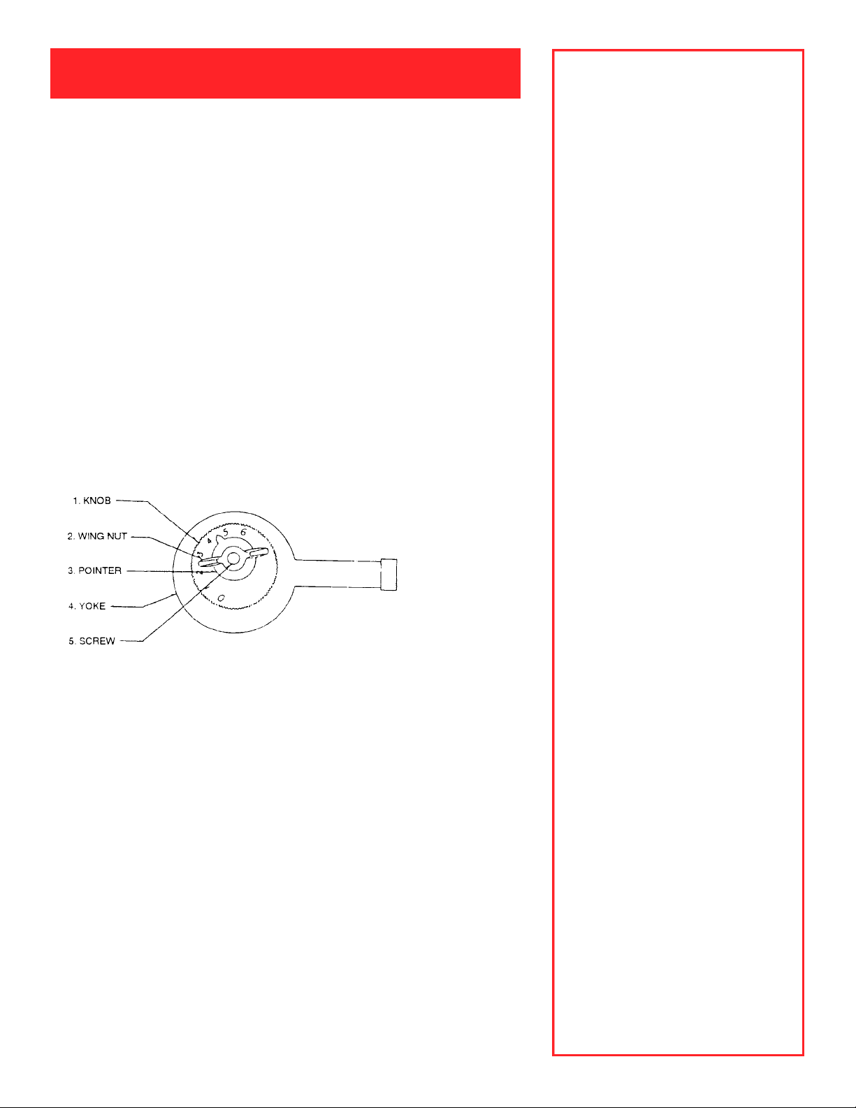
PUMP ADJUSTMENT — Pump adjustment is made by aligning the numbers
on the dial with the set point.Loosen the wing nut and rotate dial to set point,
then tighten wing nut.
Drawing 5
PUMP ADJUSTMENT CONTROL
1. Electrical Connection: USE CARE,
ensure the power supply
corresponds to that of the pump. If
you connect a 115 volt to a 230 or
240 volt line it will burn out the
winding. A 230 volt winding will not
operate on low voltage. Do not be
a l a rmed if the motor seems to
become excessively hot as shaded
pole motors operate at 50 degree
temperature rise.
2. NOTE: Keep tubing and connections away from heaters as it
becomes soft at high temperatures.
3. CAUTION: Hand tighten the tube
nuts.Do not use a wrench or pliers
to tighten the tube nuts or adapters
in the head block. This may cause
the head block to crack and would
void the warranty.
4. After your pump is in operation, a
reasonable amount of care must be
taken to keep it clean. Do not spill
chemicals on ex t e rior of pump.
C h l o rine hy p o c h l o rite leave
deposits in the pump, pump lines
and valves. In a separate container,
mix a weak solution of muriatic acid
(1/2 pint to a gallon of water), run
this through the pump to clean out
d e p o s i t . C h e ck antisyphon va l ve
occasionally to make sure this is
clean of deposits.Pumping materi a l s
that are completely, or very nearly,
soluble require little or no flushing.
5. Once every 6 months, open the oil
plug at top left of motor cover and
apply 4 drops of high temperature
oil.
NOTE:Refer to Drawing 6 for pump
assembly and part numbers.
9
Page 10
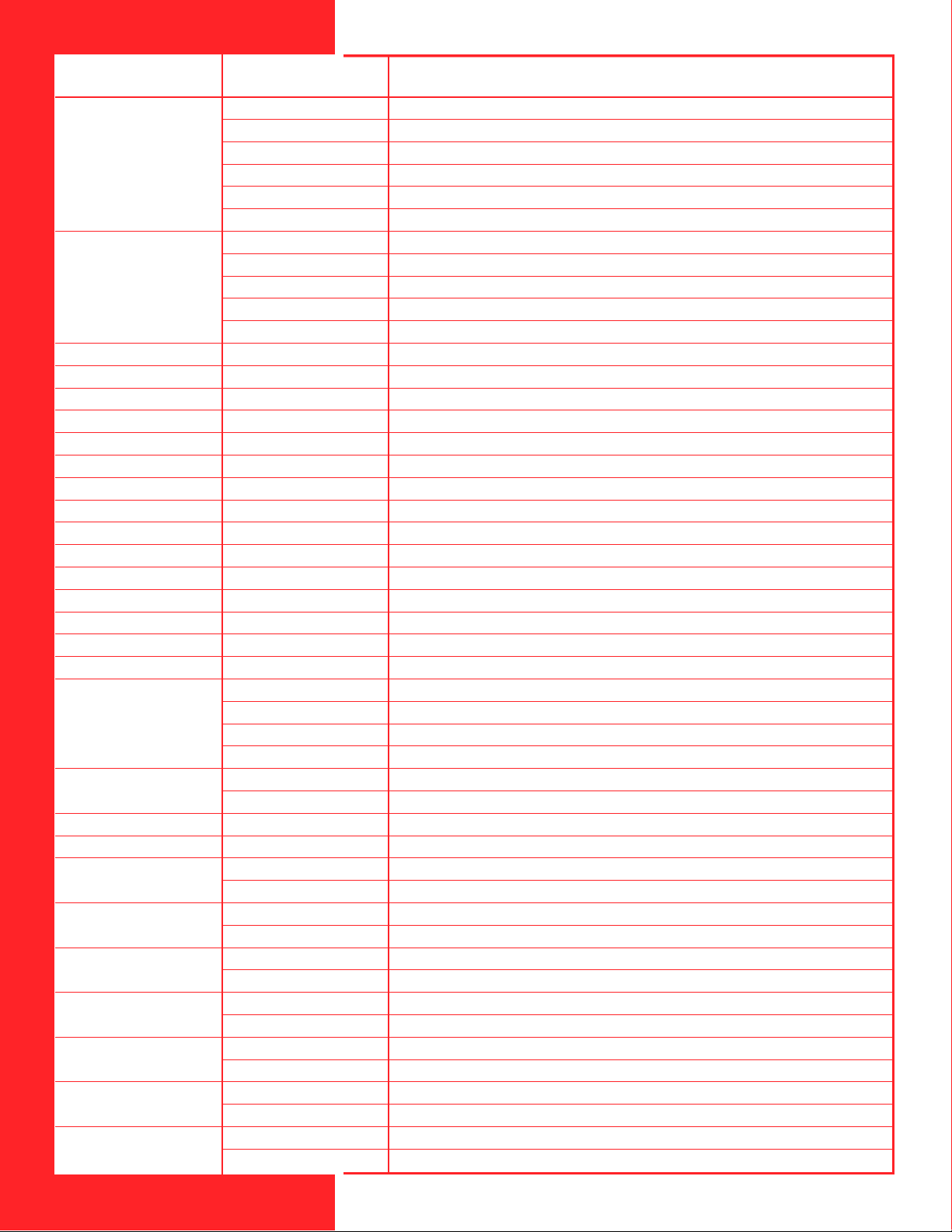
NO. PART NO. DESCRIPTION
10
1
2
3
4
5
6
7
8
9
10
11
12
13
14
15
19
17
18
19
20
21
22
23
24
25
26
27
28
C-618P-14
C-618P-30
C-618P-45
C-618P-60
C-618P-125
C-618P-250
C-615P-1
70000-603
C-615P-2
70000-604
C-615P-4
C-616PN
C-612PB
6-612F
C-625
90011-052
76000-376
90006-518
76000-304
C-628
C-608P
C-649
C-301
C-624
C-325
C-304
C-406T
C-406VT
C-406E
C-406V
C-503-1
C-503-6
C-354
C-326V-PP
C-502E
C-502V
C-427-6
C-427-4
C-330-6
C-330-4
C-334-6
C-334-4
C-335-6
C-335-4
C-395-6V
C-395-4V
C-345-6V
C-345-4V
GEARBOX S/A 14 RPM
GEARBOX S/A 30 RPM
GEARBOX S/A 45 RPM
GEARBOX S/A 60 RPM
GEARBOX S/A 125 RPM
GEARBOX S/A 250 RPM
STATOR S/A 115V/60HZ BLUE-BLACK LEADS
STATOR S/A 115V/60HZ BLUE-YELLOW LEADS
STATOR S/A 230V/60HZ RED-BLACK LEADS
STATOR S/A 230V/60HZ RED-YELLOW LEADS
STATOR S/A 24V/60HZ BLUE-WHITE LEADS
ROTOR S/A W/SHAFT AND SPACERS
BEARING BRACKET W/BEARING
FAN
SCREW 8-32 X 2.50 PHIL
SCREW 8-32 X .375 PHIL
COVER, JUNCTION BOX, SM
GASKET SEAL, JUNCTION BOX, SM
JUNCTION BOX, SM
SCREW 6-32 X 2.75 PHIL
COVER MOTOR C-600
BUSHING 1/2-20 X .31 ALUM HEX
MOTOR MOUNT C-600
SCREW 10-32 X .50 PHIL W/PATCH
CAM S/A C-600
YOKE W/BEARING
DIAPHRAGM S/A EP-TEFLON FACE
DIAPHRAGM S/A VITON/TEFLON FACE
DIAPHRAGM S/A EP
DIAPHRAGM S/A VITON
PUMP HEAD LG ACRYLIC
PUMP HEAD LG POLYPROPYLENE
SPRING COMPRESSION PUMP HEAD HASTELLOY
CHECK VALVE S/A VITON GF/POLYPROPYLENE
O-RING, ADAPTER EP
O-RING, ADAPTER VITON
ADAPTER 3/8" O.D. TUBE PP
ADAPTER 1/4" O.D. TUBE PP
TUBE NUT 3/8" O.D.TUBE PP
TUBE NUT 1/4" O.D.TUBE PP
TUBING SUCTION 3/8" O.D.X 5 FT. PVC
TUBING SUCTION 1/4" O.D.X 5 FT. PVC
TUBING DISCHARGE 3/8" O.D.X 5 FT. PE
TUBING DISCHARGE 1/4" O.D. X 5 FT.PE
INJECTION/ANTI-SIPHON VALVE 3/8" O.D.6 PSI
INJECTION/ANTI-SIPHON VALVE 1/4" O.D. 6 PSI
FOOT VALVE/STRAINER 3/8" O.D.
FOOT VALVE/STRAINER 1/4" O.D.
Page 11
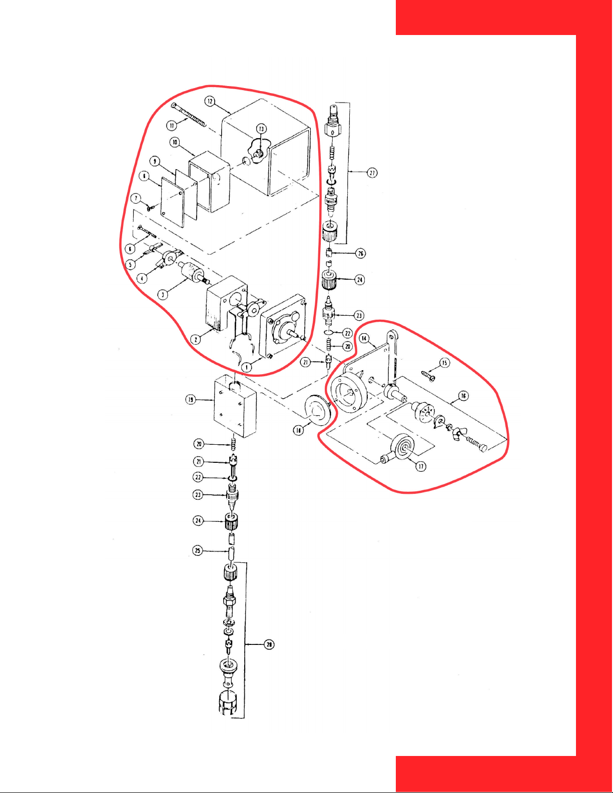
Drawing 6
*
*
* PARTS NOT AVAILABLE
INDIVIDUALLY
DETERGENT PUMP
11
Page 12
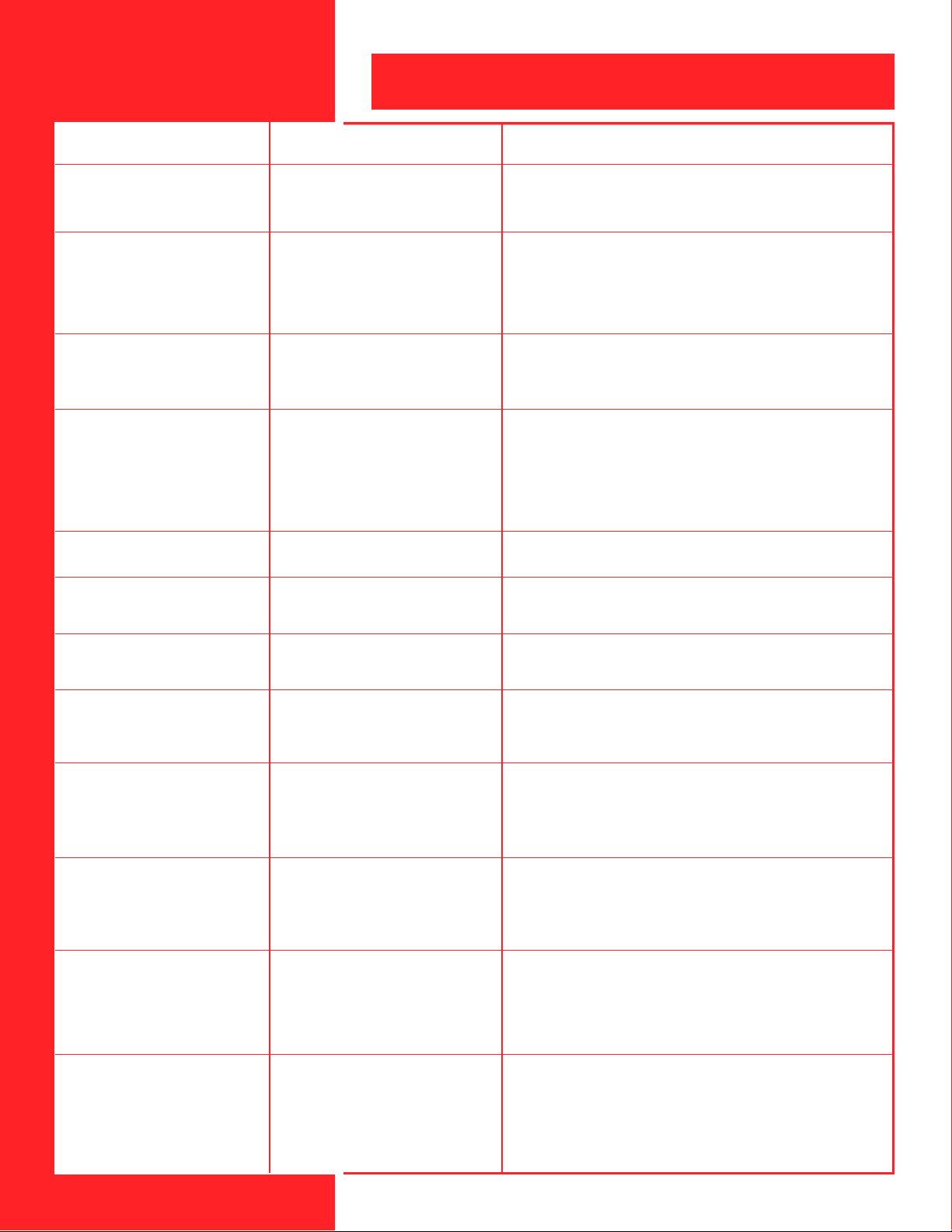
T R O U B L E S H O O T I N G G U I D E
INOPERATIVE
1) Exhaust fan and/or cold water
solenoid will not function.
2) Exhaust fan runs but no cold
water.
3) Exhaust fan does not run —
cold water functions. Fan running
at half speed.
4) Exhaust fan shuts off. Wash
cycle does not function.
5) Fan shuts off but cold water
continues to run.
PROBABLE CAUSE SOLUTION
a) No power.
a) No cold water to panel.
b) Hand valve in panel closed.
c) *Dirty strainer.
d) Defective relay.
a) No power to exhaust fan.
b) Broken fan belt.
c) Fan rotation reversed.
a) No hot water to panel.
b) Hand valve in panel closed.
c) Defective strainer.
d) Defective hot water solenoid.
e) Defective timer.
a) Dirt in cold water solenoid.
a) Check breaker panel.Check if 120V power supply has
been connected to junction box No.1 + 2 and that wires from
box No. 2 + 5 go to exhaust fan magnetic starter 120 volt coil.
a) Check main water supply to panel.
b) Check hand valve in panel.
c) Check strainer, clean if dirty.
d) Turn selector switch to run — solenoid should click, if it
does not, clean or replace if defective.
a) Check fan breaker.Check fan motor reset.
b) Check fan belt.
c) Reverse fan wheel rotation if necessary.
a) Check main water supply to panel.
b) Check hand valve in panel.
c) Check strainer, clean if dirty.
d) Turn selector switch to wash — solenoid should click, if it
does not, clean or replace if defective.
e) Check and replace if defective.
a) Clean cold water solenoid.
6) Hot water continues to run
after wash cycle is completed.
7) Water leaking from bottom of
ventilator.
8) Water leaking from above ventilator.
9) Ventilator not draining properly.
10) Little or no water.
11) Not cleaning properly.
12) Ventilator not capturing
smoke and odour (check throat
velocity).
12
a) Dirt in hot water solenoid.
a) Drain manifold not properly
tightened.
a) Ductwork not water tight.
b) Not interlocked with control panel.
Loose plumbing fittings.
a) Foreign material in bottom of
extraction chamber or drain line.
b) Ventilator not set plumb and level.
c) Drain line too small.
a) Hot and cold water supplies not
properly flushed before connection.
b) Nozzles plugged.
c) Low water pressure.
a) No detergent or wrong type.
b) Water not hot enough.
c) Hot water pressure too low or too
high.
a) Blower inadequate.
b) Blower operating backwards.
c) Drive belt slipping.
d) Dampers closed.
e) Make-up air inadequate or improperly introduced.
a) Clean hot water solenoid.
a) Tighten union — add plumbing tape if required.
a) Ductwork must be water tight.
b) Call plumber.
a) Clean extraction chamber and drain line.
b) Set plumb and level.
c) Floor drain should be 1" (25mm) larger than drain line from
ventilator.
a) Clean out all strainers.
b) Clean out nozzles.
c) Inline pump may be required for additional pressure.
a) Replace detergent bottle and check pump operation.
b) Water temperature must be 140 degrees F (60 degrees C)
minimum.
c) Add inline pump. If low, reduce to 30 PSI (207 kPa).If high
(PRV outside panel).
a) Recheck static pressure requirements and bring up to spec.
b) Change wiring.
c) Tighten or replace belt.
d) Replace fusible link.
e) Recheck and correct.
Page 13
11
THIS DRAWING IS NOT TO BE SCALED
TO
SUPPLY
TO
SUPPLY
(WASH)
(WATER MIST)
COLD WATER COLD WATER
(WATER MIST)
(WASH)
HOT WATER HOT WATER
2.5"3"
11"
2.5" 3"
VALVE
050056
1
NIPPLE
051122
051123
051125
050838
050053
7
5
4
3
2
12
15
15
10
10
11
11
23
VALVE
NIPPLE
UNION
051126
051127
050215
051116
9
8
8
3
18
19
15
17
11
12
13
2
24
051117
101112131415161718
8
8
9
14
15
7
15
16
14
3
2
27
26
25
NIPPLE
051118
4
4
ELBOW
051119
2
2
5
2
NIPPLE
051120
PRV
050469
SOLENOID VALVE
TEE
PRESSURE GAUGE
050214
051121
050066
192221
20
30
28 29
DETERGENT BOTTLE
DETERGENT LIQUID
DETERGENT PUMP
01-1 LEVEL CONTROL
050065
050493-
050619
20
22
21
22"12"
34"
TEE
NIPPLE
SOLENOID VALVE
PRV
ELBOW
UNION
HC4-25
(mm)
inches
DIMENSIONS ARE :
DRAWINGS MUST BEAR THE NAME GARLAND COMMERCIAL RANGES LIMITED
AND CAN BE REPRODUCED ONLY BY PERMISSION, IN WHICH CASE, ALL
THIS DRAWING IS THE PROPERTY OF GARLAND COMMERCIAL RANGES LIMITED
MAJOR COMPONENTS
PROJECT NAME :
OUTSIDE
ELECTRICAL
PANEL COVER
FIRE RELAY
5A. FUSE
WIRE RACEWAY
TERMINAL BLOCKS
051140
052107
050460
051130
232524
26
33
31
32
WASH TIMER
DELAY TIMER
ALARM RELAY
051136-1
050499
051138
272829
35
34
28"
BUZZER
051134
2185800
30
SILENCE BUTTON
RUN INDICATOR LAMP
052078
323331
LOW DETERGENT LAMP
WASH INDICATOR LAMP
G02315-2
G03053-1
052077
34
35
13
Page 14
UNINTERRUPTED
POWER SUPPLY
120/1/60
12
5
RUN
3
WASH
FR1/1
4
91
FR1/2
10 2
78
60 SEC.DELAY
ON MAKE TIMER
8
5
TDR1/1
FIELD WIRING
BY OTHERS
RUN
SOL
G
52
62
2
TDR1
WASH
O
H.W.
2
120V. TO
EXHAUST
FAN
120V. TO
7
MAKE UP
AIR FAN
WIRING DIAGRAM:
HC4-25
PROJECT NAME
DIMENSIONS ARE :
AND CAN BE REPRODUCED ONLY BY PERMISSION, IN WHICH CASE, ALL
THIS DRAWING IS THE PROPERTY OF VENTMASTER
inches
DRAWINGS MUST BEAR THE NAME VENTMASTER
(mm)
FR1/3
711
9
11
WIRING FOR HC4-25
10
AR1
53
AR1
15
R
3
12
15
FR1/4
SOL
DP
SILENCE
7
12
B
13
LOW DETERGENT
13
14
8
16
FR1
H.W.
AR1
2
4
8
120V. TO
N.O. CONTACT
AT MICRO
SWITCH IN
FIRE PROT.
14
PANEL
EXTRA SET OF
DRY CONTACTS
CLOSE IN FIRE
CONDITION
14
THIS DRAWING IS NOT TO BE SCALED
Page 15
VALVE
NIPPLE
UNION
ELBOW
SOLENOID VALVE
PRV
NIPPLE
TEE
PRESSURE GAUGE
DETERGENT BOTTLE
DETERGENT LIQUID
DETERGENT PUMP
THIS DRAWING IS NOT TO BE SCALED
(mm)
inches
H4-25
MAJOR COMPONENTS
TO
SUPPLY
(WASH) (WASH)
HOT WATER HOT WATER
2.5"
2.5"
050056
051122
051123
051125
050838
050053
051126
051127
9
8
7
5
4
3
2
1
8
8
19
9
3
7
17"
3
11
2
23
24
2
192221
8
4
2
2
5
2
4
27
26
25
050066
050065
20
050493-
01-1 LEVEL CONTROL
050619
20
30
28 29
DIMENSIONS ARE :
DRAWINGS MUST BEAR THE NAME GARLAND COMMERCIAL RANGES LIMITED
AND CAN BE REPRODUCED ONLY BY PERMISSION, IN WHICH CASE, ALL
THIS DRAWING IS THE PROPERTY OF GARLAND COMMERCIAL RANGES LIMITED
22
21
22"
PROJECT NAME :
34"
12"
OUTSIDE
ELECTRICAL
PANEL COVER
5A. FUSE
WIRE RACEWAY
TERMINAL BLOCKS
052107
050460
051130
232524
26
33
31
32
FIRE RELAY
ALARM RELAY
051140
051138
272829
WASH TIMER
DELAY TIMER
051136-1
050499
35
34
28"
BUZZER
RUN WASH SELECTOR
RUN INDICATOR LAMP
051134
052078
2185800
323331
30
SILENCE BUTTON
LOW DETERGENT LAMP
WASH INDICATOR LAMP
G02315-2
G03053-1
052077
34
35
15
Page 16
UNINTERRUPTED
POWER SUPPLY
120/1/60
12
5
RUN
3
WASH
FR1/1
4
91
FR1/2
10 2
78
60 SEC.DELAY
ON MAKE TIMER
8
5
TDR1/1
FIELD WIRING
BY OTHERS
RUN
G
52
62
2
TDR1
WASH
O
120V. TO
EXHAUST
FAN
120V. TO
7
2
MAKE UP
AIR FAN
H4- 25
WIRING DIAGRAM:
PROJECT NAME
DIMENSIONS ARE :
AND CAN BE REPRODUCED ONLY BY PERMISSION, IN WHICH CASE, ALL
THIS DRAWING IS THE PROPERTY OF VENTMASTER
inches
DRAWINGS MUST BEAR THE NAME VENTMASTER
(mm)
FR1/3
711
9
11
WIRING FOR H4-25
10
AR1
53
AR1
15
R
3
12
15
FR1/4
SOL
DP
SILENCE
7
12
B
13
LOW DETERGENT
13
14
8
16
FR1
H.W.
AR1
2
4
8
120V. TO
N.O. CONTACT
AT MICRO
SWITCH IN
FIRE PROT.
14
PANEL
EXTRA SET OF
DRY CONTACTS
CLOSE IN FIRE
CONDITION
16
THIS DRAWING IS NOT TO BE SCALED
Page 17
NIPPLE051084
23
NIPPLE051085
24
NIPPLE051086
25
050969 SHUT OFF VALVE
051087 NIPPLE
27
26
NIPPLE
050994
28
UNION
050998
ELBOW
050999
NIPPLE
051144
312930
TEE051012
32
REDUCING BUSHING051014
PRESSURE SWITCH
050970
33
34
PRESSURE GAUGE
REDUCING BUSHING
CLOSED NIPPLE
050967
051015
050995
37
36
35
NIPPLE
FLOW SWITCH
050966
050996
39
38
NIPPLE051124
65
THIS DRAWING IS NOT TO BE SCALED
(mm)
inches
MAJOR COMPONENTS
HC4-25/SU3-150
(WATER MIST)
COLD WATER
SUPPRESSOR
(FIRE PROTECTION)
SUPPLY TO
SUPPLY TO
COLD WATER
(WATER MIST)
SUPPLY TO
HOT WATER
(WASH)
14"
(FIRE PROTECTION)
SUPPRESSOR
3.5" 3.5"
(WASH)
2.5" 3" 2.5"3"
HOT WATER
VALVE
050056
1
NIPPLE
051122
2
UNION
051123
3
1
10
29
10
1
40
15
27
ELBOW
051125
4
8
12
38
11
41
SOLENOID VALVE
PRV
050838
050053
7
5
3
38
32
39
29
28
12
3
2
49
TEE
NIPPLE
VALVE
NIPPLE
UNION
NIPPLE
051126
051127
050215
051116
051117
9
8
101112131415161718
13
353236
37
31
33
34
31
28
13
25
051083
26
19
18
14
15
30
23
17
32
23
16
30
11
14
40
41
42
ELBOW
051119
9
7
4344
45
47
NIPPLE
051120
8
24
PRV
SOLENOID VALVE
050469
050214
4
24
5
65
4
48
TEE
051121
192221
20
46
PRESSURE GAUGE
DETERGENT LIQUID
DETERGENT PUMP
01-1 LEVEL CONTROL
050066
050065
050493-
20
22
21
50
DETERGENT BOTTLE
DIMENSIONS ARE :
DRAWINGS MUST BEAR THE NAME GARLAND COMMERCIAL RANGES LIMITED
AND CAN BE REPRODUCED ONLY BY PERMISSION, IN WHICH CASE, ALL
THIS DRAWING IS THE PROPERTY OF GARLAND COMMERCIAL RANGES LIMITED
050619
32"
44"
12"
PROJECT NAME :
5A. FUSE
WIRE RACEWAY
TERMINAL BLOCKS
052107
050460
051130
404241
OUTSIDE
ELECTRICAL
PANEL COVER
FIRE RELAY
ALARM RELAY
051140
051138
444546
43
51
WASH TIMER
DELAY TIMER
051136-1
050499
47
535455
52
BUZZER
FIRE TEST KEY SWITCH
PRINTED CIRCUIT BOARD
2185800
050980
050965
485049
56
40"
RUN WASH SELECTOR
RUN INDICATOR LAMP
BACK-UP BATTERY
050988
58
57
WASH INDICATOR LAMP
051134
052078
052077
525351
62
60
59
61
SILENCE BUTTON
LOW DETERGENT LAMP
ALARM BUZZER
G02315-2
G03053-1
052144
54
55
56
64
63
FIRE INDICATOR LAMP
052017
57
POWER ON KEY SWITCH
8A. FUSE
POWER INDICATOR LAMP
050982
050976
052018
59
HAND VALVE CLOSED LAMP
LOW WATER INDICATOR LAMP
GAS RESET SWITCH
GAS ON INDICATOR LAMP
052016
050974
052016
636462
052018
615860
17
Page 18
18
Page 19
NIPPLE051084
23
NIPPLE051085
24
NIPPLE051086
25
SHUT OFF VALVE
050969
051087 NIPPLE
27
26
NIPPLE
050994
28
UNION
050998
ELBOW
050999
NIPPLE
051144
312930
TEE051012
32
REDUCING BUSHING051014
PRESSURE SWITCH
050970
33
35
34
PRESSURE GAUGE
REDUCING BUSHING
CLOSED NIPPLE
050967
051015
050995
37
36
NIPPLE
050996
38
39
FLOW SWITCH
NIPPLE051124
050966
65
THIS DRAWING IS NOT TO BE SCALED
(mm)
inches
H4-25/SU3-150
MAJOR COMPONENTS
(WATER MIST)
COLD WATER
SUPPRESSOR
(FIRE PROTECTION)
SUPPLY TO
SUPPLY TO
COLD WATER
(WATER MIST)
(WASH)
SUPPLY TO
HOT WATER
(WASH)
14"
(FIRE PROTECTION)
SUPPRESSOR
3.5" 3.5"
2.5" 3" 2.5"3"
HOT WATER
VALVE
050056
1
NIPPLE
051122
2
UNION
051123
3
1
10
29
27
10
1
40
ELBOW
051125
4
12
15
38
11
41
SOLENOID VALVE
PRV
050838
050053
7
5
3
8
32
39
29
28
12
3
2
49
TEE
NIPPLE
VALVE11NIPPLE12UNION13NIPPLE14ELBOW15NIPPLE16PRV17SOLENOID VALVE
051126
051127
050215
051116
051117
051083
051119
9
8
10
26
19
18
13
38
30
353236
37
34
28
13
17
31
33
32
31
16
30
25
40
41
42
051120
9
8
14
15
23
7
23
11
14
4344
45
47
24
050469
4
4
050214
24
5
65
TEE19PRESSURE GAUGE
DETERGENT PUMP
051121
050066
050065
18
20
22
21
20
46
48
50
DETERGENT BOTTLE
DETERGENT LIQUID
01-1 LEVEL CONTROL
050493-
050619
22
21
32"
44"
12"
DIMENSIONS ARE :
DRAWINGS MUST BEAR THE NAME GARLAND COMMERCIAL RANGES LIMITED
AND CAN BE REPRODUCED ONLY BY PERMISSION, IN WHICH CASE, ALL
THIS DRAWING IS THE PROPERTY OF GARLAND COMMERCIAL RANGES LIMITED
PROJECT NAME :
5A. FUSE
WIRE RACEWAY
TERMINAL BLOCKS
052107
050460
051130
404241
OUTSIDE
ELECTRICAL
PANEL COVER
FIRE RELAY
ALARM RELAY
051140
051138
444546
43
51
WASH TIMER
DELAY TIMER
051136-1
050499
47
535455
52
BUZZER
FIRE TEST KEY SWITCH
PRINTED CIRCUIT BOARD
2185800
050980
050965
485049
56
40"
RUN WASH SELECTOR
RUN INDICATOR LAMP
BACK-UP BATTERY
050988
57 58
WASH INDICATOR LAMP
051134
052078
052077
525351
59 60
61 62
ALARM BUZZER
SILENCE BUTTON
LOW DETERGENT LAMP
G02315-2
G03053-1
052144
54
55
57
56
64
63
8A. FUSE
FIRE INDICATOR LAMP
052017
POWER ON KEY SWITCH
POWER INDICATOR LAMP
050982
050976
052018
586059
HAND VALVE CLOSED LAMP
LOW WATER INDICATOR LAMP
GAS RESET SWITCH
GAS ON INDICATOR LAMP
052016
050974
052016
636462
052018
61
19
Page 20
20
Page 21

V E N T M A S T E R L I M I T E D W A R R A N T Y
Vent Master, (“Manufacturer”), warrants only to its direct purchasers, and to
no others, that all products manufactured and sold by Manufacturer shall be
free from defect in materials and workmanship for a period of twelve (12)
months from the date of original installation and start-up, or eighteen (18)
months from the date of shipment, whichever first occurs.
Manufacturer also agrees to pay all reasonable labour costs necessary to
repair or replace, at Manufacturer’s option, defective parts subject to this
warrant for a period of ninety (90) days after installation or eighteen (18)
months from the date of shipment, whichever first occurs, on all products
sold but not manufactured by Manufacturer. All labour costs subject hereto
shall be performed during standard work hours at straight-time rates.
Manufacturer agrees to pay all reasonable labour costs necessary to repair
or replace, at Manufacturer’s option, defective parts subject to this warranty
for a period of twelve (12) months after installation or eighteen (18) months
from the date of shipment, whichever first occurs, on all products sold and
manufactured by Manufacturer. All labour costs subject hereto shall be
performed during standard work hours at straight-time rates.
Purchaser shall pay any incurred premium labour charges, including overtime, weekends and holidays. Travel time, service charges, miscellaneous
tools, material charges, and labour charges resulting from inaccessibility of
equipment will not be paid by Manufacturer.
This Limited Warranty Shall Apply Only to products that have been
installed and maintained in accordance with the Installation and Care
Instruction Manuals. Purchaser shall be solely responsible for adhering to
the instructions and procedures set forth in said instruction manuals.
This Limited Warranty Shall not be applicable to any damage or defect
resulting from fire, flood, freezing or any Act of God, abu s e, misuse, accident,
neglect or failure to adhere to all instructions set forth in the Installation and
Care instructions manuals.Furthermore, this limited warranty shall not apply
to any product that has been altered, unless such alteration has been
approved in writing by a duly authorized representative of the Manufacturer.
In no event shall Manufacturer be liable for any loss, expense, personal
injuries or consequential damage, of any kind or character, as may result
from a defect in materials, and/or workmanship, however caused.
EXCEPT AS IS EXPRESSLY SET FORTH IN THIS LIMITED WARRANTY,
MANUFACTURER MAKES NO WARRANTY OF MARKETABILITY FOR
FITNESS OR ANY PA RTICULAR PURPOSE. NEITHER DOES
MANUFACTURER MAKE ANY WARRANTY, EXPRESSED OR IMPLIED,
WITH RESPECT TO PRODUCTS SOLD BY MANUFACTURER OR AS TO
THE USE THEREOF.
21
Page 22
T H E I N S T A L L A T I O N O F T H E V E N T I L A T O R S A N D T H E
D U C T W O R K C O N N E C T I O N S S H O U L D B E I N S T A L L E D I N
A C C O R D A N C E W I T H N F P A 9 6 A N D L O C A L C O D E S .
THE INSTALLATION AND CONNECTION OF ELECTRICAL COMPONENTS SHOULD COMPLY WITH
ALL APPLICABLE NATIONAL & LOCAL CODES.
ENSURE ELECTRICAL SUPPLY CONFORMS WITH ELECTRICAL CHARACTERISTICS SHOWN ON
THE RATING PLATE.
Continuous product improvement is a Vent Master policy, therefore specifications and design are subject to change without notice.
Enodis
1021 Brevik Place Tel: 905-624-0301 Fax: 905-624-5547
Mississauga, Ontario Tel: US to Canada 1-800-565-2981
Canada L4W 3R7 Fax: US to Canada 1-800-665-2438
Form No.WATERWINS (04/01)
 Loading...