

Page 1
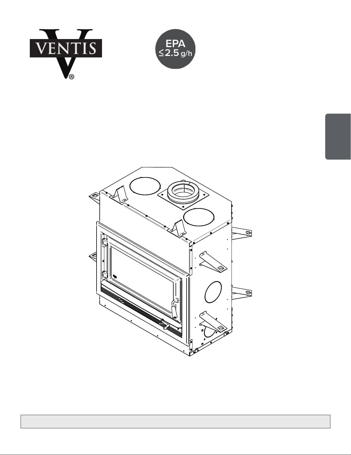
Safety tested according to ULC S610,
UL 127 standards by an accredited
US Environmental Protection Agency
phase II certified wood fireplace
compliant with 2020 cord wood standard.
Installation and Operation Manual
HE275CF
laboratory.
(VB00017 model)
ENGLISH
CONTACT LOCAL BUILDING OR FIRE OFFICIALS ABOUT RESTRICTIONS AND INSTALLATION INSPECTION REQUIREMENTS IN
LOCAL AREA.
READ THIS ENTIRE MANUAL BEFORE INSTALLATION AND USE OF THIS WOOD FIREPLACE. FAILURE TO FOLLOW THESE
INSTRUCTIONS COULD RESULT IN PROPERTY DAMAGE, BODILY INJURY OR EVEN DEATH.
READ AND KEEP THIS MANUAL FOR REFERENCE
Printed in Canada 46181A
2020-05-28
Page 2

Page 3

THANK YOU FOR CHOOSING
THIS WOOD FIREPLACE
If this fireplace is not
installed properly,
combustible materials
near it may overheat
and catch fire.
To reduce the
risk of fire, follow
the installation
instructions in this
manual.
As one of North America’s
largest and most respected
wood stove and fireplace
manufacturers, Stove Builder
International takes pride in the
quality and performance of all
its products.
The following pages
provide general advice on
wood heating, detailed
instructions for safe and
effective installation, and
guidance on how to get the
best performance from this
fireplace.
It is highly recommended
that this wood burning hearth
product be installed and
serviced by professionals who
are certified by a «Qualified
Agency» such as NFI (National
Fireplace Institute®) or CSIA
(Chimney Safety Institute of
America) in the United States
and in Canada by WETT
(Wood Energy Technology
Transfer) or in Quebec
by APC (Association des
Professionnels du Chauffage).
Contact local building or fire
officials about restrictions
and installation inspection
requirements in your local
area.
A building permit might be
required for the installation of
this fireplace and the chimney
that it is connected to. It is
also highly recommended to
inform your home insurance
company.
Please read this entire manual
before installing and using this
fireplace.
A primary alternative heat
source should be available in
the home. This heating unit
may serve as a supplementary
heat source. The manufacturer
cannot be responsible for
additional heating costs
associated with the use of an
alternative heat source.
ENGLISH
ONLINE WARRANTY REGISTRATION
If the unit requires repairs during the warranty period, proof of purchase must be provided. The
purchase invoice must be kept. The date indicated on it establishes the warranty period. If it
cannot be provided, the warranty period will be determined by the date of manufacture of the
product. It is also highly recommended to register the warranty online at
http://www.occanada.com/en/service-support/warranty/warranty-registration
Registering the warranty will help to quickly find the information
needed on the unit.
Installation and Operation Manual - HE275CF
Page 3
Page 4

TABLE OF CONTENTS
PART A - OPERATION AND MAINTENANCE .............................................................................. 7
1. Safety Information ................................................................................................................... 7
2. General Information ................................................................................................................ 8
2.1 Performances .................................................................................................................. 8
2.2 Specifications ................................................................................................................. 9
2.3 Dimensions ....................................................................................................................10
2.4 Materials........................................................................................................................13
2.5 Zone Heating .................................................................................................................13
2.6 Emissions and Efficiency .................................................................................................14
3. Fuel ........................................................................................................................................ 14
3.1 Tree Species ..................................................................................................................15
3.2 Log Length ....................................................................................................................15
ENGLISH
3.3 Piece Size .....................................................................................................................15
3.4 Compressed Wood Logs .................................................................................................16
3.5 Drying Time ...................................................................................................................16
4. Operating the Fireplace ........................................................................................................ 17
4.1 Using a Fire Screen ........................................................................................................17
5. Burning Wood Efficiently ...................................................................................................... 17
5.1 First Use ........................................................................................................................17
5.2 Lighting Fires .................................................................................................................17
5.3 Combustion Cycles ........................................................................................................19
5.4 Rekindling a Fire .............................................................................................................20
5.5 Removing Ashes ............................................................................................................20
5.6 Air Intake Control ...........................................................................................................21
5.7 Fire Types ......................................................................................................................21
6. Maintenance .......................................................................................................................... 23
6.1 Cleaning and Painting .....................................................................................................23
6.2 Refractory Material and Baffle ..........................................................................................23
6.3 Glass Door ....................................................................................................................24
6.4 Door .............................................................................................................................25
6.5 Exhaust System .............................................................................................................28
PART B – INSTALLATION ........................................................................................................... 29
7. Safety Information and Standards ....................................................................................... 30
7.1 Safety ...........................................................................................................................30
7.2 Standards ......................................................................................................................30
8. Fireplace Installation ............................................................................................................. 31
8.1 Standoff installation ........................................................................................................31
8.2 Carrying Handles ............................................................................................................31
8.3 Location ........................................................................................................................31
8.4 Clearances to combustibles ............................................................................................32
8.5 Framing construction ......................................................................................................32
8.6 Hearth Extension Construction .........................................................................................37
8.7 Facing ...........................................................................................................................40
Page 4
Installation and Operation Manual - HE275CF
Page 5

8.8 Combustible Shelf Installation ..........................................................................................41
8.9 Combustible/non Combustible Shelf Installation .................................................................41
9. The Venting System .............................................................................................................. 41
9.1 Location ........................................................................................................................41
9.2 Supply of Combustion Air ................................................................................................42
9.3 Chimney Installation ........................................................................................................42
9.4 Angled Wall Pass-Thru Installation ....................................................................................47
9.5 Chimney Support Installation ............................................................................................47
9.6 Approved Chimneys .......................................................................................................48
Appendix 1: Installation of the required Air Intake ................................................................... 49
Appendix 2: Optional Traditional Gravity Hot Air Distribution Kit Installation ........................ 52
Appendix 3: Optional Modern Gravity Hot Air Distribution Kit Installation ............................. 56
Appendix 4: Optional Forced Air Distribution Kit Installation .................................................. 61
Appendix 5: Optional Fire Screen Installation .......................................................................... 62
Appendix 6: Refractory Panels Replacement .......................................................................... 63
Appendix 7: Secondary Air Tubes and Baffle Installation ....................................................... 64
ENGLISH
Appendix 8: Exploded Diagram and Parts List ........................................................................ 65
VENTIS Limited Lifetime Warranty ............................................................................................ 68
Dealer:
Installer:
Phone Number:
Serial Number:
Installation and Operation Manual - HE275CF
Page 5
Page 6
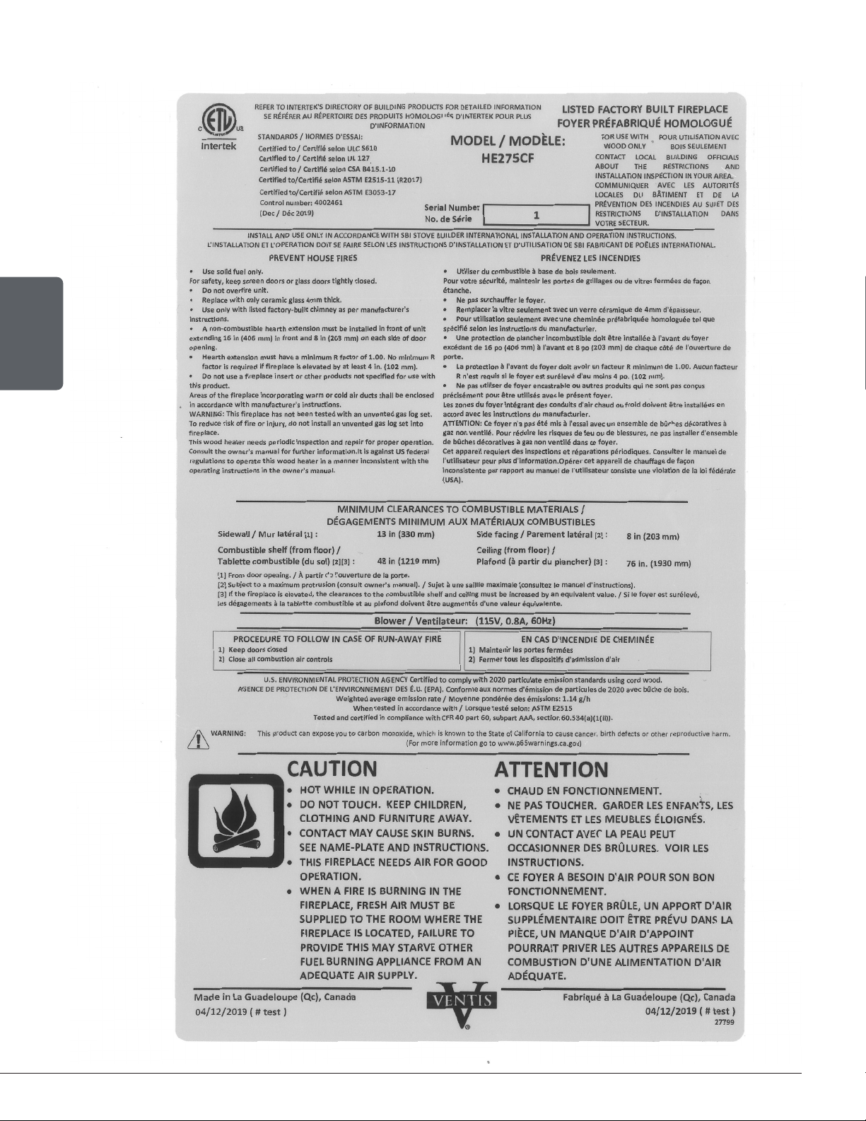
CERTIFICATION PLATE
ENGLISH
Page 6
Installation and Operation Manual - HE275CF
Page 7

PART A - OPERATION AND MAINTENANCE
1. Safety Information
• This fireplace has been tested for use with an open door in conjunction with a fire screen, sold
separately. The door may be opened, or fire screen removed only during lighting procedures or
reloading. Always close the door or put back on the fire screen after ignition. Do not leave the
fireplace unattended when the door is opened with or without a fire screen.
• WARNING : OPERATE ONLY WITH THE DOOR FULLY CLOSED OR FULLY OPEN WITH THE
FIRE SCREEN IN PLACE. IF THE DOOR IS LEFT PARTLY OPEN, GAS AND FLAME MAY BE
DRAWN OUT OF THE OPENING, CREATING RISKS FROM BOTH FIRE AND SMOKE.
• HOT WHILE IN OPERATION. KEEP CHILDREN, CLOTHING AND FURNITURE AWAY.
CONTACT MAY CAUSE SKIN BURNS. GLOVES MAY BE NEEDED FOR THE FIREPLACE
OPERATION.
• Using a fireplace with cracked or broken components, such as glass, firebricks or baffle may
produce an unsafe condition and may damage the fireplace.
• NEVER USE GASOLINE, LANTERN FUEL (NAPHTHA), FUEL OIL, MOTOR OIL, KEROSENE,
CHARCOAL LIGHTER FLUID, OR SIMILAR LIQUIDS OR AEROSOLS TO START A FIRE
IN THIS FIREPLACE. KEEP ALL SUCH LIQUIDS OR AEROSOLS WELL AWAY FROM THE
FIREPLACE WHILE IT IS IN USE.
• Do not store fuel within heater minimum installation clearances.
• Burn only seasoned natural firewood.
• This wood heater needs periodic inspection and repairs for the proper operation. It is against
federal regulations to operate this wood heater in a manner inconsistent with operating instructions
in this manual.
• Do not obstruct air inlets. This fireplace needs air for its good operation.
• Do not block the hot air vents of the fireplace as this will cause the fireplace to overheat.
• A smoke detector, a carbon monoxide detector and a fire extinguisher should be installed in the
house. Location of detectors should be chosen wisely to avoid false alarm when reloading the
appliance. The location of the fire extinguisher should be known by all family members.
ENGLISH
• Do not use makeshift materials or make any compromises when installing this fireplace.
• Mixing of appliance components from different sources or modifying components is prohibited
and will void the warranty. Any modification of the fireplace that has not been approved in
writing by the testing authority is prohibited and violates CSA B365 and NFPA 211 standards.
• The manufacturer grants no warranty, implied or stated, for the poor installation or lack of
maintenance of this fireplace and assumes no responsibility for any consequential damages.
• Do not elevate the fire by means of grates, chenets, andirons or any other means.
WARNING This product can expose you to chemicals including carbon monoxide,
which is known to the State of California to cause cancer, birth defects or other
reproductive harm. For more information go to www.P65warnings.ca.gov/
Installation and Operation Manual - HE275CF
Page 7
Page 8

2. General Information
2.1 Performances
Values are as measured per test method, except for the recommended heating area, firebox volume,
maximum burn time and maximum heat output.
Model HE275CF (VB00017)
Fuel Type Dry Cordwood
Combustion Technology Non-Catalytic
Recommended heating area (sq. ft.
.)1
ENGLISH
Overall firebox volume 2.5 ft
EPA loading volume 1.69 ft
Maximum burn time
Maximum heat output (dry cordwood)
Overall heat output rate (min. to max.)
Average overall efficiency
Dry cordwood
Optimum efficiency
Average particulate emissions rate
1
2
2 3
3
6
7
750 to 2,200 ft2 (69 to 204 m2)
3
(0.071 m3)
3
(0.048 m3)
8 hours
80,000 BTU/h (23.4 kW)
14,200 BTU/h to 48,200 BTU/h
(4.16 kW to 14.13 kW)
68 % (HHV)
4
73 % (LHV)
74 %
1.14 g/h (EPA / CSA B415.1-10)
5
8
Average CO
1
Recommended heating area and maximum burn time may vary subject to location in home, chimney draft,heat loss factors, climate, fuel type
9
53 g/h
and other variables. The recommended heated area for a given appliance is dened by the manufacturer as its capacity to maintain a minimum
acceptable temperature in the designated area in case of a power failure.
2
The maximum heat output (dry cordwood) is based on a loading density varying between 15 lb/ft3 and 20 lb/ft3. Other performances are based on
a fuel load prescribed by the standard. The specied loading density varies between 7 lb/ft³ and 12 lb/ft3. The moisture content is between 19%
and 25%.
3
As measured per CSA B415.1-10 stack loss method.
4
Higher Heating Value of the fuel.
5
Lower Heating Value of the fuel.
6
Optimum overall efciency at a specic burn rate (LHV).
7
This appliance is ofcially tested and certied by an independent agency.
8
Tested and certied in compliance with CFR 40 part 60, subpart AAA, section 60.534(a)(1(ii) and ASTM E3053-17.
9
Carbon monoxide.
Page 8
Installation and Operation Manual - HE275CF
Page 9

2.2 Specifications
Maximum log length
10
20 in (508 mm) east-west
Flue outlet diameter 6 in (150 mm)
Recommended connector pipe diameter 6 in (150 mm)
Type of chimney ULC-S629, UL 103 HT (2100 °F)
Baffle material C-Cast
Approved for mobile home installation
11
No
Type of door Simple, glass with steel frame
Type of glass Ceramic glass
Particulate emission standard
12
EPA / CSA B415.1-10
USA standard (Safety) UL 127
ENGLISH
Canada standard (Safety) ULC S610
10
North-south: ends of the logs visible, East-west: sides of the logs visible.
11
Mobile homes (Canada) or manufactured homes (USA): The US Department of Housing and Urban Development describes “manufactured homes”
better known as “mobile homes” as follows; buildings built on xed wheels and those transported on temporary wheels/axles and set on a permanent
foundation. In Canada, a mobile home is a dwelling for which the manufacture and assembly of each component is completed or substantially
completed prior to being moved to a site for installation on a foundation and connection to service facilities and which conforms to the CAN/CSAZ240 MH standard.
12
Tested and certied in compliance with CFR 40 part 60, subpart AAA, section 60.534(a)(1(ii) and ASTM E3053-17.
Installation and Operation Manual - HE275CF
Page 9
Page 10
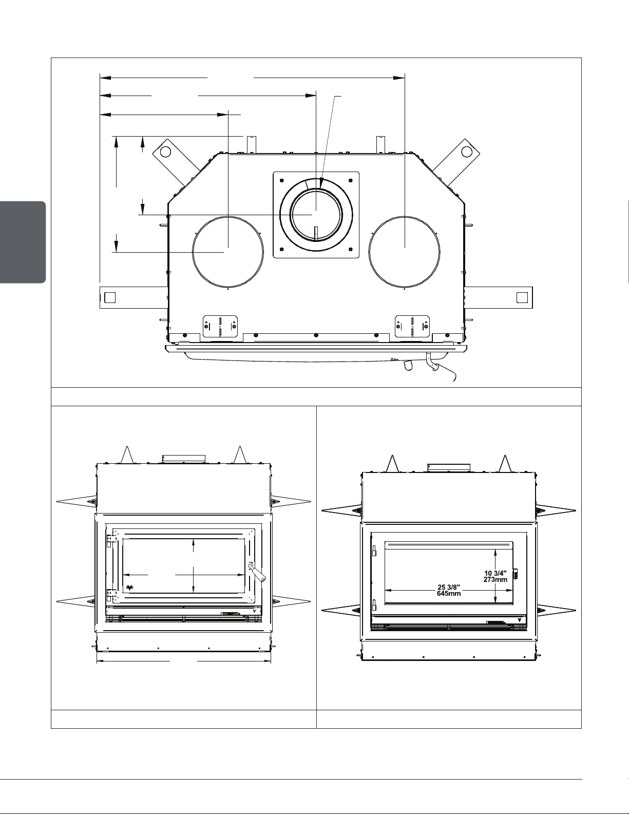
2.3 Dimensions
25 1/8"
638mm
9 1/8"
231mm
13 3/8"
341mm
35 3/8"
898mm
14 7/8"
378mm
6"
ø
152mm
ENGLISH
G
G
Top view
10 5/8"
271mm
24"
611mm
34 3/8"
874mm
Front view Front view - Door opening
G : Opening for gravity hot air distribution kit (ø 8").
Page 10
Installation and Operation Manual - HE275CF
Page 11
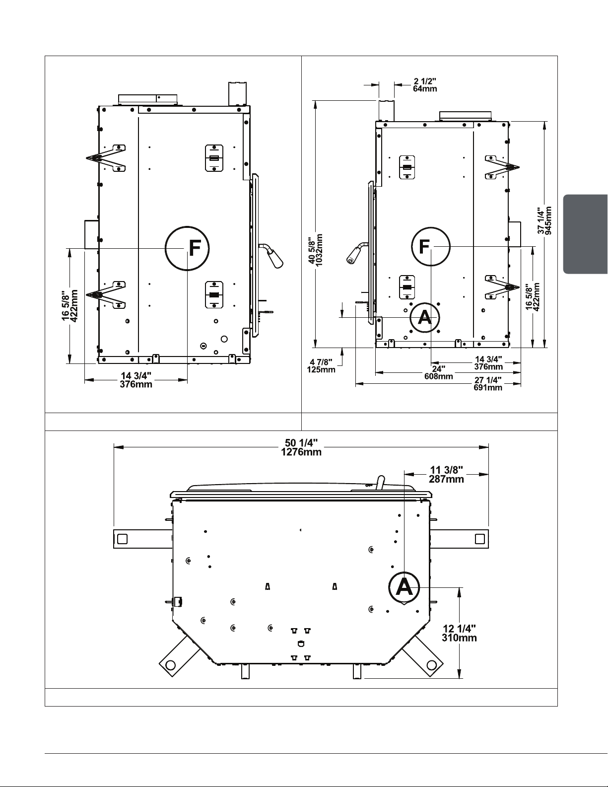
Left side view Right side view
ENGLISH
F : Opening for forced air distribution kit (ø 6").
A : Opening for fresh air intake (ø 4").
Installation and Operation Manual - HE275CF
Bottom view
Page 11
Page 12
ENGLISH
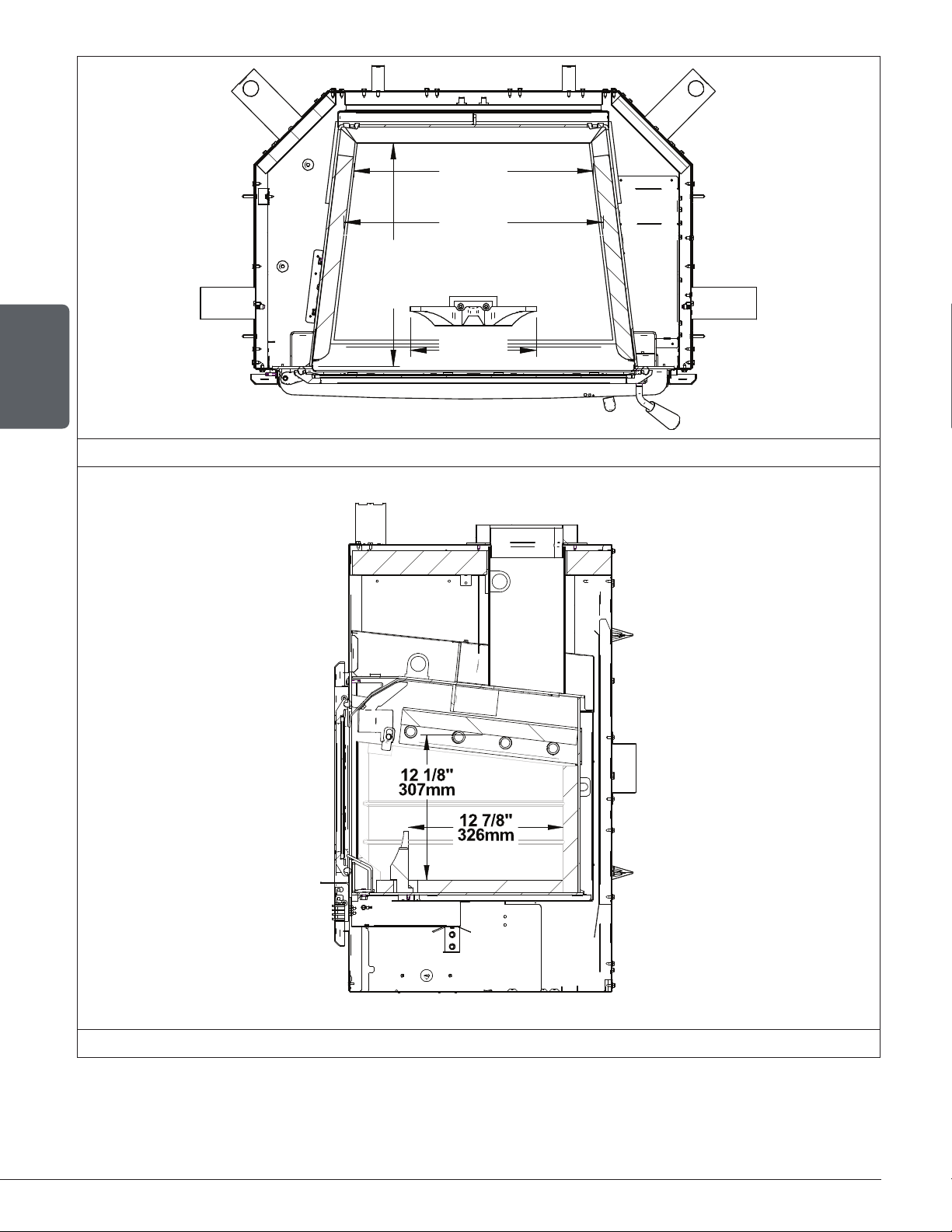
18 7/8"
479mm
20 3/8"
518mm
17 1/2"
446mm
9 7/8"
252mm
Combustion chamber - Top view
Page 12
Combustion chamber - Side view
Installation and Operation Manual - HE275CF
Page 13

2.4 Materials
The body of this fireplace, which is most of its weight, is carbon steel. Should it ever become
necessary many years in the future, almost the entire fireplace can be recycled into new products,
thus eliminating the need to mine new materials.
The paint coating on the fireplace is very thin. Its VOC content (Volatile Organic Compounds)
is very low. VOCs can be responsible for smog, so all the paint used during the manufacturing
process meets the latest air quality requirements regarding VOC reduction or elimination.
The air tubes are stainless steel, which can also be recycled.
The baffle is made of aluminosilicate fibre material that is compressed with a binder to form a
rigid board. C-Cast can withstand temperatures above 2,000 °F. It is not considered hazardous
waste. Disposal at a waste management center is recommended.
Moulded refractory panels are mainly composed of silicon dioxide, also known as silica, a
product processed from a mined mineral. It is most commonly found in nature in the form
of sand and clay. Disposal at a waste management center is recommended. The steel mesh
contained in some refractory bricks can also be recycled.
The door and glass gaskets are fibreglass which is spun from melted sand. Black gaskets
have been dipped into a solvent-free solution. Disposal at a waste management center is
recommended.
The door glass is a 3/16" (5 mm) thick ceramic material that contains no toxic chemicals. It is
made of natural raw materials such as sand and quartz that are combined in such a way to form
a high temperature glass. Ceramic glass cannot be recycled in the same way as normal glass, so
it should not be disposed of with regular household products. Disposal at a waste management
center is recommended.
2.5 Zone Heating
This fireplace is a space heater, which means it is intended to heat the area it is installed in,
as well as spaces that connect to that area, although to a lower temperature. This is called
zone heating and it is an increasingly popular way to heat homes or spaces within homes. Zone
heating can be used to supplement another heating system by heating a particular space within
a home, such as a basement, a family room or an addition that lacks another heat source.
ENGLISH
Houses of moderate size and relatively new construction can be heated with a properly sized
and located wood fireplace. Whole house zone heating works best when the fireplace is in the
part of the house where the family spends most of its time. This is normally the main living area
where the kitchen, dining and living rooms are located.
Locating the fireplace in this area will give the maximum benefit of the heat it produces and will
achieve the highest possible heating efficiency and comfort. The space where the most time is
spent will be warmest, while bedrooms and basement (if there is one) will stay cooler. In this
way, less wood is burnt than with other forms of heating.
Although the fireplace may be able to heat the main living areas of the house to an adequate
temperature, it is strongly recommended to also have a conventional oil, gas or electric heating
system to provide backup heating.
Installation and Operation Manual - HE275CF
Page 13
Page 14

The success of zone heating will depend on several factors, including the correct sizing and
location of the fireplace, the size, layout and age of your home and your climate zone. Threeseason vacation homes can usually be heated with smaller fireplaces than houses that are
heated all winter.
2.6 Emissions and Efficiency
The low smoke emissions produced by the special features inside this fireplace firebox mean
that the household will release up to 90% less smoke into the outside environment than if an
older conventional fireplace was used. But there is more to the emission control technologies
than protecting the environment.
The smoke released from wood when it is heated contains about half of the energy content
of the fuel. By burning the wood completely, this fireplace releases all the heat energy from
the wood instead of wasting it as smoke up the chimney. Also, the features inside the firebox
allow control of the air supply meaning controlling the heat output, while maintaining clean and
efficient flaming combustion, which boosts the efficient delivery of heat to the home.
ENGLISH
The emission control and advanced combustion features of this fireplace can only work properly
if the fuel used is in the correct moisture content range of 15% to 20%. Refer to the following
section of suggestions on preparing fuelwood and judging its moisture.
3. Fuel
Good firewood has been cut to the correct length for the fireplace, split to a range of sizes and
stacked in the open until its moisture content is down to 15% to 20%.
DO NOT BURN:
• GARBAGE;
• LAWN CLIPPINGS OR YARD WASTE;
• MATERIALS CONTAINING RUBBER,
INCLUDING TIRES;
• MATERIALS CONTAINING PLASTIC;
• WASTE PETROLEUM PRODUCTS, PAINTS
OR PAINT THINNERS, OR ASPHALT
PRODUCTS;
• MATERIALS CONTAINING ASBESTOS;
• CONSTRUCTION OR DEMOLITION DEBRIS;
• RAILROAD TIES OR PRESSURE-TREATED
WOOD;
• MANURE OR ANIMAL REMAINS;
• SALT WATER DRIFTWOOD OR OTHER
PREVIOUSLY SALT WATER SATURATED
MATERIALS;
• UNSEASONED WOOD; OR
• PAPER PRODUCTS, CARDBOARD,
PLYWOOD, OR PARTICLE BOARD. THE
PROHIBITION AGAINST BURNING THESE
MATERIALS DOES NOT PROHIBIT THE USE
OF FIRE STARTERS MADE FROM PAPER,
CARDBOARD, SAW DUST, WAX AND
SIMILAR SUBSTANCES FOR THE PURPOSE
OF STARTING A FIRE IN AN AFFECTED
WOOD HEATER.
BURNING THESE MATERIALS MAY RESULT IN THE RELEASE OF TOXIC FUMES OR
RENDER THE HEATER INEFFECTIVE AND CAUSE SMOKE.
Page 14
Installation and Operation Manual - HE275CF
Page 15
3.1 Tree Species
The tree species the firewood is produced from is less important than its moisture content. The
main difference in firewood from various tree species is the density of the wood. Hardwoods are
denser than softwoods.
Homeowners with access to both hardwood and softwood use both types for different purposes.
Softer woods make good fuel for mild weather in spring and fall because they light quickly and
produce less heat.
Softwoods are not as dense as hardwoods so a given volume of wood contains less energy.
Using softwoods avoids overheating the house, which can be a common problem with wood
heating in moderate weather. Harder woods are best for colder winter weather when more heat
and longer burn cycles are desirable.
Hardwood trees like oak, maple, ash and beech are slower growing and longer lived than softer
woods like poplar and birch. That makes hardwood trees more valuable. The advice that only
hardwoods are good to burn is outdated. Old, leaky cast iron fireplaces wouldn’t hold a fire
overnight unless they were fed large pieces of hardwood.
3.2 Log Length
ENGLISH
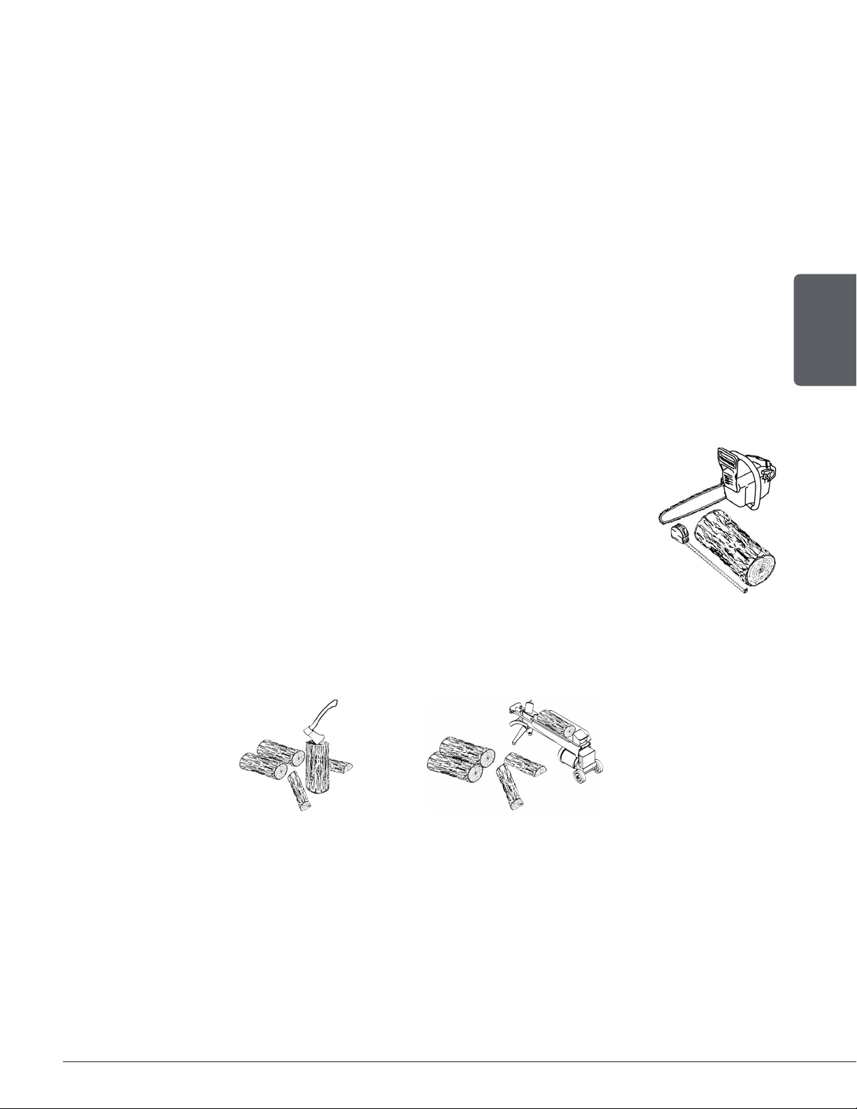
Logs should be cut at least 1" (25 mm) shorter than the firebox so they fit in
easily. Pieces that are even slightly too long makes loading the fireplace very
difficult. The most common standard length of firewood is 16" (400 mm).
3.3 Piece Size
Firewood dries more quickly when it is split. Large unsplit rounds can take years to dry enough
to burn. Even when dried, unsplit logs are difficult to ignite because they don’t have the sharp
edges where the flames first catch.
Wood should be split to a range of sizes, from about 3" to 6" (75 mm to 150 mm) in cross
section. Having a range of sizes makes starting and rekindling fires much easier.
Installation and Operation Manual - HE275CF
Page 15
Page 16
3.4 Compressed Wood Logs
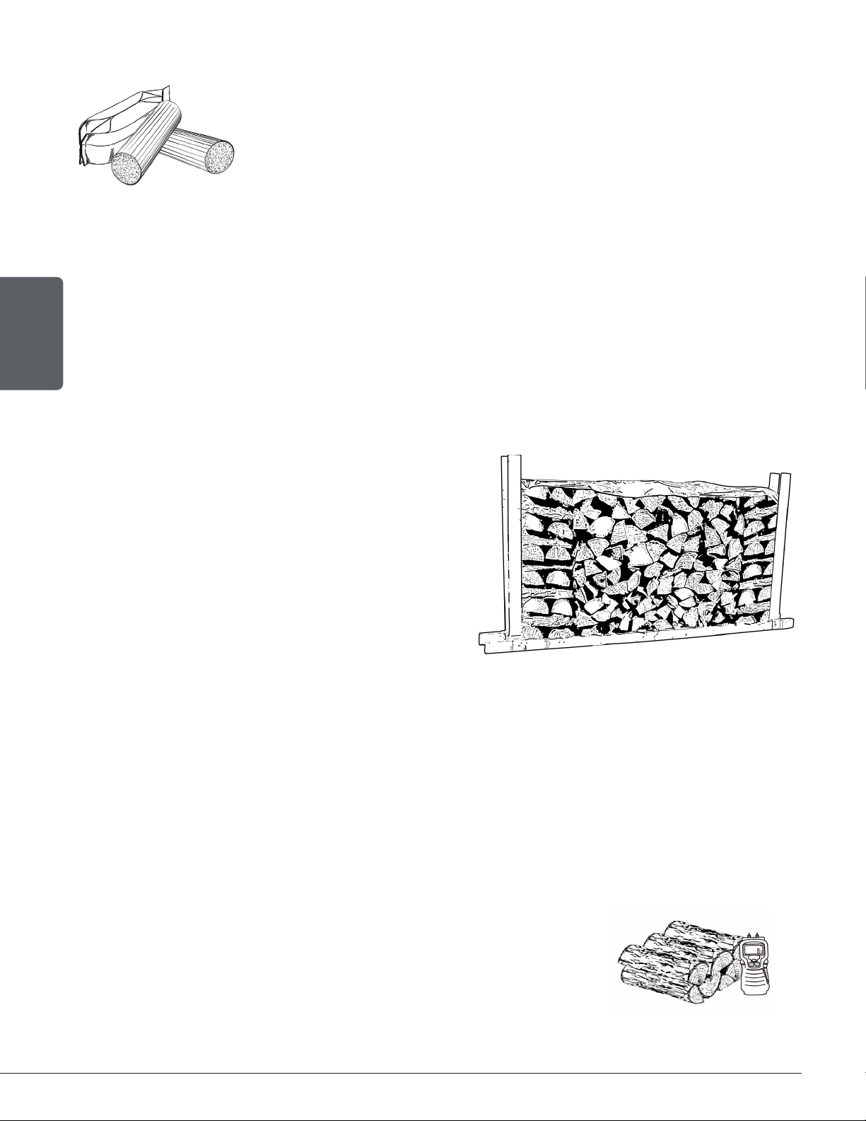
Compressed wood logs made of 100% compressed sawdust can be
burned with caution in the number of these logs burned at once. Do
not burn compressed logs made of wax impregnated sawdust or logs
with any chemical additives. Do not poke or stir the logs while they
are burning.
Use only logs that meet the requirements of ULC/ORD C127 M1990 for composite logs.
Refer to package cautions and warnings before using logs.
3.5 Drying Time
Firewood that is not dry enough to burn is the cause of most complaints about wood-burning
appliances. Continually burning green or unseasoned wood produces more creosote and involves
lack of heat and dirty glass door. Firewood with a moisture content between 15% and 20% will
ENGLISH
allow the fireplace to produce its highest possible efficiency.
Here are some facts to consider in estimating drying time:
− Firewood bought from a dealer is rarely dry enough
to burn, so it is advisable to buy the wood in spring
and dry it yourself;
− Drying happens faster in dry weather than in a
damp climate;
− Drying happens faster in warm summer weather
than in winter weather;
− Split pieces dry more quickly than unsplit rounds;
− Softwoods like pine, spruce, poplar, and aspen
take less time to dry than hardwoods. They can be dry enough to burn after being stacked to air
dry only for the summer months;
− Hardwoods like oak, maple and ash can take one, or even two years to dry fully, especially if the
pieces are big;
− Firewood dries more quickly when stacked outside in a location exposed to sun and wind; it takes
much longer to dry when stacked in a wood shed;
− Firewood with a moisture content of 15% to 20% will allow the fireplace to reach its highest
efficiency.
Firewood is dry enough to burn when:
− Cracks form at the end of logs;
− The wood turns from white or cream colored to grey or yellow;
− Two pieces of wood struck together sounds hollow;
− The face of a fresh cut feels warm and dry;
− The moisture content read by a moisture meter is between 15% to 20%.
Page 16
Installation and Operation Manual - HE275CF
Page 17
4. Operating the Fireplace
This wood heater has a manufacturer-set minimum low burn rate that
must not be altered. It is against federal regulations to alter this setting or
otherwise operate this wood heater in a manner inconsistent with operating
instructions in this manual.
4.1 Using a Fire Screen
This product should not be operated with door open using fire screen (AC01275) in the United
States or provinces where any particulate matter emission rate limit is enforced (ex: US EPA).
This fireplace has been tested for use with an open door in conjunction with a fire screen, sold
separately. The fire screen must be properly secured on the fireplace to avoid any risk of sparks
damaging the flooring. When the fire screen is in use, do not leave the fireplace unattended
to respond promptly in the event of smoke spillage into the room. Potential causes of smoke
spillage are described in Section «9. The Venting System» of this manual. See «Appendix 5:
Optional Fire Screen Installation» for installation instructions.
Operating the fireplace with a fire screen increases possibilities of generating carbon monoxide.
Carbon monoxide is an odourless gas that is highly toxic which can cause death at high concentration
in air. Installation of a carbon monoxide detector is highly recommended.
ENGLISH
5. Burning Wood Efficiently
5.1 First Use
Two things happen when burning the first few fires; the paint cures and the internal components are
conditioned. As the paint cures, some of the chemicals vaporize. The vapors are not poisonous,
but they smell bad. Fresh paint fumes can also trigger false alarms in smoke detectors. When
lighting the heater for the first few times, it may be wise to open doors and windows to ventilate
the house.
Burn two or three small fires to begin the curing and conditioning process. Then build bigger
and hotter fires until there is no longer paint smell from the fireplace. As hotter and hotter fires
are burned, more of the painted surfaces reach the curing temperature of the paint. The smell of
curing paint does not disappear until one or two very hot fires have been burned.
5.2 Lighting Fires
Each person heating with wood develops its own favorite way to light fires. Regardless of the
method chosen, the goal should be to have a hot fire burning, quickly. A fire that ignites fast
produces less smoke and deposits less creosote in the chimney.
Never use gasoline, gasoline-type lantern fuel (naphtha), fuel oil, motor oil,
kerosene, charcoal lighter fluid, or similar liquids or aerosols to start or
‘freshen up’ a fire in this wood fireplace. Keep all such liquids well away from
the fireplace while it is in use.
Here are three popular and effective ways to ignite wood fires.
Installation and Operation Manual - HE275CF
Page 17
Page 18
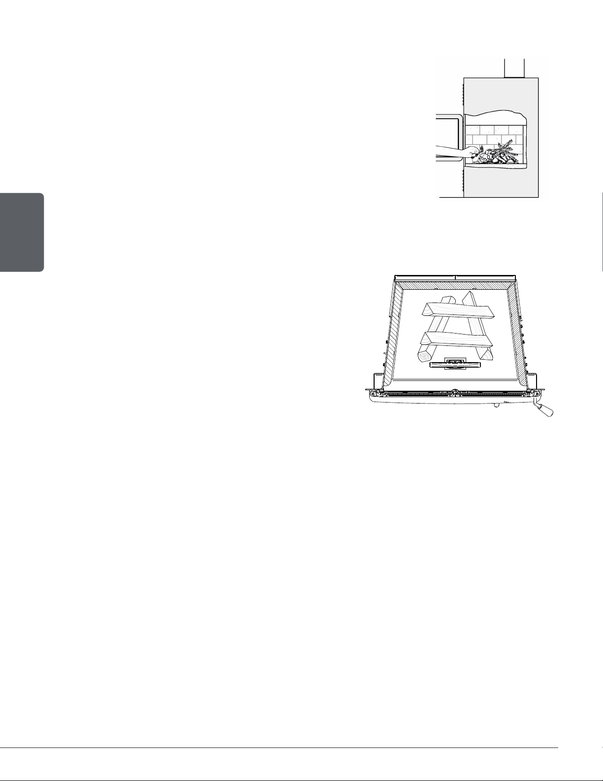
5.2.1 Conventional Method
The conventional method to build a wood fire is to crumple 5 to 10
sheets of newspaper and place them in the firebox and hold them in
place with ten pieces of kindling wood. The kindling should be placed
on and behind the newspaper.
Then add two or three small pieces of firewood. Open the air intake
control completely and ignite the newspaper. Leave the door slightly
ajar. Once the fire has ignited, the door can be closed with the air
control still fully open. When the kindling is almost completely burned,
standard firewood pieces can be added.
Do not leave the fireplace unattended when the door is slightly
open. Always close and latch the door after the fire ignites.
5.2.2 The Top Down Method
ENGLISH
This method is the opposite of the conventional method
and only works properly if well-seasoned wood is used.
Place three or four small, split, dry logs in the firebox.
Arrange the kindling wood on the logs in two layers at
right angles and place a dozen finely split kindling on the
second row. It is possible to use ragged paper but it may
not hold in place since it tends to roll while it is burning.
The best is to wrap a sheet on itself, grab the ends of the
roll and make a knot.
Use four or five sheets of paper tied together and put
them on top and around the kindling. Open the air intake control completely, ignite the paper
and close the door.
The top down fire method has two advantages over the traditional method: first, the fire does
not collapse on itself, and it is not necessary to add wood gradually since the combustion
chamber is full before the fire is lit.
The following load orientation is the one who will give the best performance for this fireplace.
The figure below is for reference only. The quantity and size of the logs may vary.
5.2.3 Two Parallel Logs Method
Two spit logs are placed in the firebox with a few sheets of twisted newspapers in between the
logs. Fine kindling is added across the two logs and some larger kindling across those, log cabin
style. Newspaper is lit.
Page 18
Installation and Operation Manual - HE275CF
Page 19

5.2.4 Using Fire Starters
Commercial fire starters can be used instead of a newspaper. Some of these starters are made
of sawdust and wax and others are made of specialized flammable solid chemicals. Always
follow the package directions when using.
Gel starters can also be used, but only to light a fire, in a cold combustion chamber without hot
embers inside.
5.3 Combustion Cycles
Wood heating with a space heater is very different than other forms of heating. There will be
temperature variations in different parts of the house and there will be temperature variations
throughout day and night. This is normal, and for experienced wood burners these are advantages
of zone heating wood burning.
Wood heaters don’t have a steady heat output. It is normal for the temperature to rise after
a new load of wood is ignited and for its temperature to gradually decrease throughout the
burning cycle.
This increasing and decreasing temperature can be matched with the household routines. For
example, the temperature in the area can be cooler when the household is active, and it can be
warmer when it is inactive.
ENGLISH
Wood burns best in cycles. A cycle starts when a new load of wood is ignited by hot coals and
ends when that load has been consumed down to a bed of charcoal about the same size as it
was when the wood was loaded.
Trying to produce a steady heat output by placing a single log on the fire at regular intervals
is not recommended. Always place at least three, and preferably more pieces on the fire at a
time so that the heat radiated from one piece helps to ignite the pieces next to it. Each load of
wood should provide several hours of heating. The size of each load may vary depending on the
amount of heat required.
Burning in cycles means the loading door does not need to be opened while the wood is flaming.
This is an advantage since it is preventing smoke leaking from the heater when the door is
opened as a full fire is burning. This is especially true if the chimney is on the outside wall of the
house.
If the door must be opened while the fire is flaming, fully open air control for a few
minutes then open the door slowly.
Installation and Operation Manual - HE275CF
Page 19
Page 20
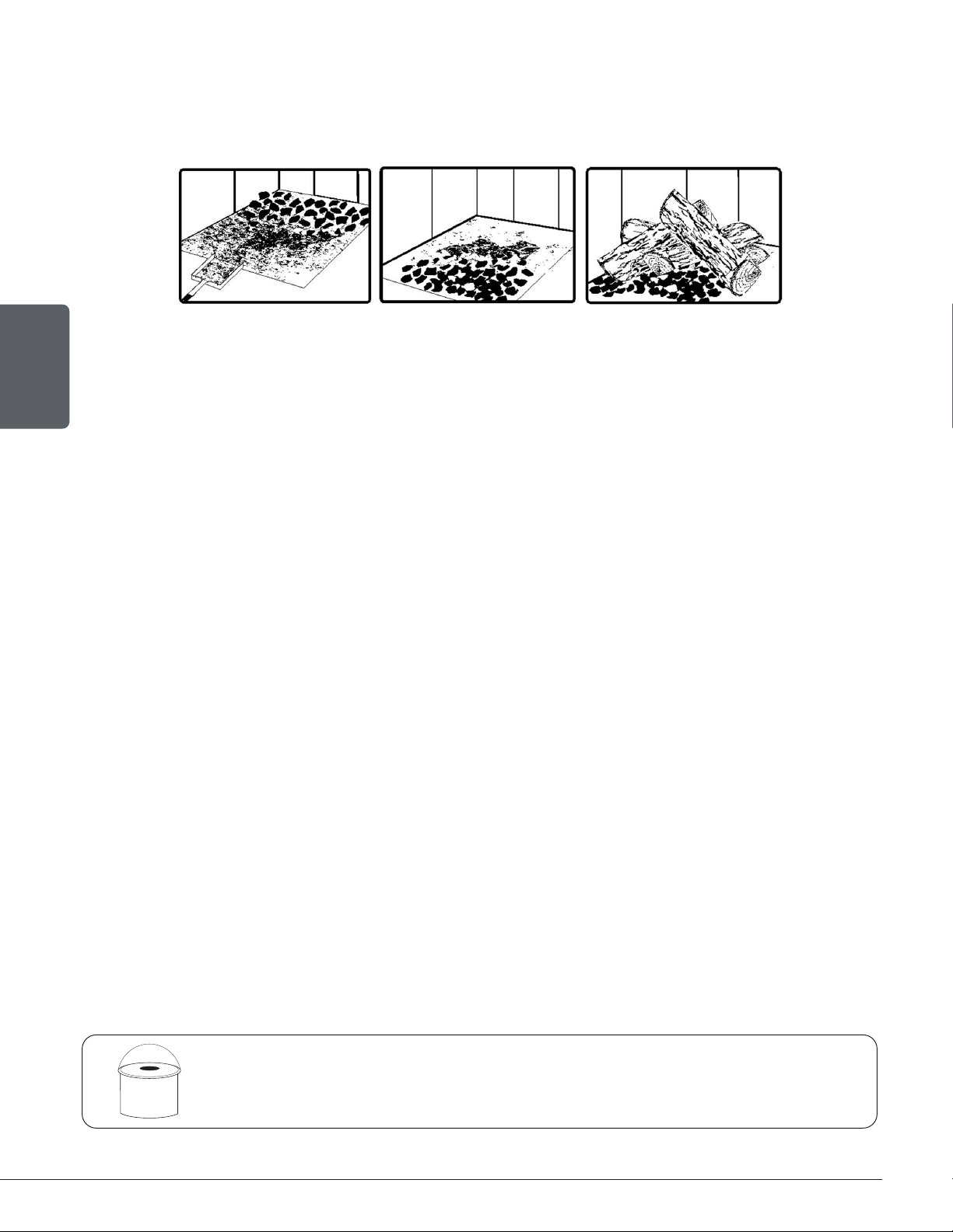
5.4 Rekindling a Fire
When the temperature of the room is lower and all that remains is embers, it is time to reload.
Remove excess ash from the front of the firebox and bring the ashes forward. Place a new load
of wood on, and at the back of the embers. Open the air control completely and close the door.
Raking the coals is useful for two reasons. First, it brings them near where most of the combustion
air enters the firebox. This will ignite the new load quickly. Secondly, the charcoal will not be
smothered by the new load of wood. When the embers are simply spread inside the combustion
chamber, the new load smoulder for a long time before igniting.
ENGLISH
Close the air control only when the firebox is full of bright turbulent flames, the wood is charred,
and its edges are glowing.
The heater should not be left unattended during ignition and the fire should not
burn at full intensity for more than a few minutes.
When lighting a new load, the appliance produces a heat surge. This heat surge is pleasant when
the room temperature is cool but can be unpleasant when the room is already warm. Therefore,
it is best to let each load of wood burn completely so that the room cools down before putting
a load of wood back on.
5.5 Removing Ashes
Ash should be removed from the firebox every two to three days of full-time heating. Ash
should not accumulate excessively in the firebox since it will affect the proper operation of the
appliance.
The best time to remove ash is in the morning, after an overnight fire when the fireplace is
relatively cold, but there is still a little chimney draft to draw the ash dust into the fireplace and
prevent going out into the room.
Ashes should be placed in a tightly covered metal container. The container must
be placed on a non-combustible floor or on the ground well away from all
combustible materials. Ashes almost always contain live embers that can stay
hot for days and which release carbon monoxide gas. If the ashes are disposed
of by burial in soil or otherwise locally dispersed, they should be kept in a closed
metal container until they are completely cooled. No other waste should be
placed in this container.
Page 20
CENDRES
ASHES
NEVER STORE ASHES INDOORS OR IN A NON-METALLIC CONTAINER
OR ON A WOODEN DECK.
Installation and Operation Manual - HE275CF
Page 21
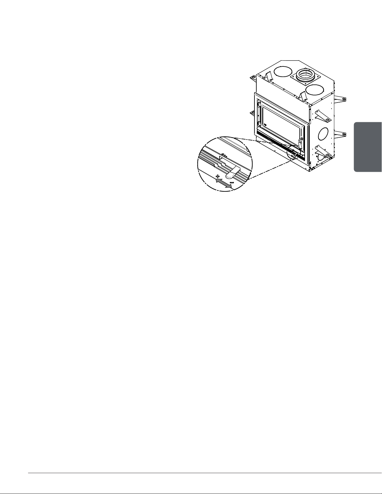
5.6 Air Intake Control
Once the firewood, firebox and chimney are hot, air intake can be reduced to achieve a steady
burn.
As the air intake is reduced, the burn rate
decreases. This has the effect of distributing the
thermal energy of the fuel over a longer period of
time. In addition, the flow rate of exhaust through
the appliance and flue pipe slows down, which
increases the duration of the energy transfer of
the exhaust gases. As the air intake is reduced,
the flame slows down.
If the flames diminish to the point of disappearing,
the air intake has been reduced too early in the
combustion cycle or the wood used is too wet.
If the wood is dry and the air control is used
properly, the flames should decrease, but remain
bright and stable.
DETAIL A
A
ENGLISH
On the other hand, too much air can make the fire uncontrollable, creating very high temperatures
in the unit as well as in the chimney and seriously damaging them. A reddish glow on the unit
and on the chimney components indicates overheating. Excessive temperatures can cause a
chimney fire.
5.7 Fire Types
Using the air intake control is not the only way to match the fireplace heat output to the desired
temperature in the house. A house will need far less heating in October than in January to
maintain a comfortable temperature. Filling the firebox full in fall weather will overheat the space.
Otherwise, the combustion rate will have to be reduced to a minimum and the fire will be smoky
and inefficient.
Here are some suggestions for building fires suitable for different heating needs.
5.7.1 Flash Fire
To build a small fire that will produce a low heat output, use small pieces of firewood and load
them crisscross in the firebox. The pieces should only be 3" (76 mm) to 4" (102 mm) in diameter.
After raking the coals, lay two pieces parallel to each other diagonally in the firebox and lay two
more across them in the other direction. Open the air control fully and only reduce the air after
the wood is fully flaming.
This kind of fire is good for mild weather and should provide enough heat for up to four hours.
Small fires like this are a good time to use softer wood species and avoid overheating the house.
5.7.2 Low and Long Output Fires
For a fire that will last up to eight hours but will not produce intense heat, use soft wood and
place the logs compactly in the firebox. Before reducing the air intake, the load will have to burn
at full heat for long enough for charring the surface of the logs. The flame must be bright before
letting the fire burn by itself.
Installation and Operation Manual - HE275CF
Page 21
Page 22

5.7.3 High Output Fires
When heating needs are high during cold weather, the fire should burn steadily and brightly. This
is the time to use larger pieces of hardwood. Place the biggest pieces at the back of the firebox
and place the rest of the pieces compactly. A densely built fire like this will produce the longest
combustion this fireplace is capable of. Special attention must be paid when building fires like
this since if the air intake is reduced too quickly, the fire could smoulder. The wood must be
flaming brightly before leaving the fire to burn.
5.7.4 Maximum Burn Cycle Times
The burn cycle time is the period between loading wood on a coal bed and the consumption of
that wood back to a coal bed of the same size. The flaming phase of the fire lasts for roughly
the first half of the burn cycle and the second half is the coal bed phase during which there is
little or no flame. The burning time expected from this fireplace, including both phases, will vary
depending on a number of things, such as:
ENGLISH
− firebox size,
− the amount of wood loaded,
− the species of wood,
− the wood moisture content,
− the size of the space to be heated,
− the climate zone where the house is, and
− the time of the year.
The table below gives an approximate maximum burn cycle times, based on firebox volume.
Table 1 : Approximate Maximum Burn Cycle Time
FIREBOX VOLUME MAXIMUM BURN CYCLE TIME
<1.5 cubic feet 3 to 5 hours
1.5 c.f. to 2.0 c.f 5 to 6 hours
2.0 c.f. to 2.5 c.f. 6 to 8 hours
2.5 c.f. to 3.0 c.f. 8 to 9 hours
>3.0 c.f. 9 to 10 hours
A longer burning time is not necessarily an indication of efficient fireplace operation. It is
preferable to build a smaller fire that will provide three or four hours of heating than to fully load
the firebox for a much longer burn. Shorter burn cycles make it easier to match the heat output
of the fireplace to the heat demand for the space.
5.7.5 Logs Orientation
In a relatively square firebox, the wood can be loaded north-south (ends of the logs visible) or
east-west (sides of the logs visible).
North-south loads allow more wood to be loaded at the same time. On the other hand, they
break into smaller pieces faster. North-south loading is good for high output, long lasting fires
for cold weather.
East-west loads allow a limited amount of wood since too many logs could cause them to fall
on the glass. East-west loads, placed in a compact way, take a long time before breaking down.
They are excellent for low-intensity, long-lasting fires in relatively mild weather.
Page 22
Installation and Operation Manual - HE275CF
Page 23

5.7.6 Carbon Monoxide
When there is no more flame in the firebox and there are still some unburned logs, check outside
if there is smoke coming out of the chimney. If this is the case, it means that the fire is out of
air to burn properly. In this situation, the level of CO increase and it is important to react. Open
the door slightly and move the logs with a poker. Create a passage for the air below by making
a trench with the ember bed. Add small pieces of wood to restart the combustion.
6. Maintenance
This heater will give many years of reliable service if used and maintained properly. Internal
components of the firebox such as firebricks or refractory panels, baffle and air tubes will wear
over time. Defective parts should always be replaced with original parts.
To avoid premature deterioration, follow the lighting and reloading procedures in section
«5. Burning Wood Efficiently» and also avoid letting the heater run with the air intake fully open
for entire burn cycles.
6.1 Cleaning and Painting
Painted and plated surfaces can be wiped down with a soft, damp cloth. If the paint is scratched
or damaged, it is possible to repaint the fireplace with a heat-resistant paint.
ENGLISH
Do not clean or paint the fireplace when it is hot.
Before painting, the surface should be sanded lightly with sandpaper and then wiped off to
remove dust. Apply two thin layers of paint.
6.2 Refractory Material and Baffle
The intense heat of the fire can cause slight cracks in the refractory panels. It is possible to
minimize the appearance of these cracks by hardening the panels as described in the section
«5.1 First Use». Slight cracks will not reduce the effectiveness of the panels. On the other hand,
if wider cracks appears, they must be replaced. Inspect the refractory panels and the baffle for
damage periodically and replace anything that is cracked or broken.
Operation of the heater with a cracked or missing baffle may cause unsafe temperatures
and hazardous conditions and will void the warranty.
Installation and Operation Manual - HE275CF
Page 23
Page 24
6.3 Glass Door
6.3.1 Cleaning
Under normal conditions, the door glass should stay relatively clear. If the firewood is dry
enough and the operating instructions in this manual are followed, a whitish, dusty deposit will
form on the inner surface of the glass after a week or so of use. This is normal and can be easily
removed when the heater is cold by wiping with a damp cloth or paper towel and then drying.
When the fireplace runs at a low combustion rate, light brown stains may form, especially in the
lower corners of the glass. This indicates that the fire has been smoky and some of the smoke
has condensed on the glass. It also indicates incomplete combustion of the wood, which also
means more smoke emissions and faster formation of creosote in the chimney.
The deposits that form on the glass are the best indication of the fuel quality and success
in properly using the fireplace. These stains can be cleaned with a special wood stove glass
cleaner. Do not use abrasive products to clean the glass.
ENGLISH
The goal should be having a clear glass with no brown stains. If brown stains appear regularly
on the glass, something about the fuel or the operating procedure needs to be changed. When
brown streaks are coming from the edge of the glass, it is time to replace the gasket around the
glass. Always replace the gasket with a genuine one.
Do not clean the glass when the fireplace is hot.
Do not abuse the glass door by striking or slamming shut.
Do not use the fireplace if the glass is broken.
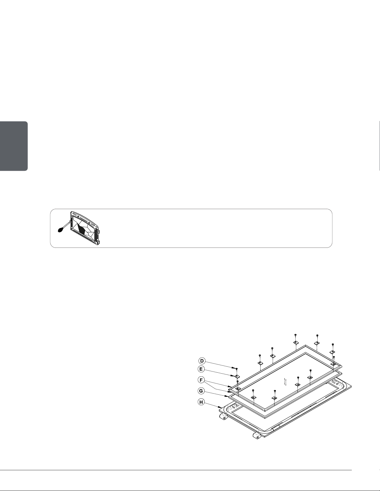
6.3.2 Replacement
The glass used is a ceramic glass, 5/32» (4 mm) thick, 24 7/8» x 11 3/4» (632 mm x 298 mm)
tested to reach temperatures up to 1400º F. If the glass breaks, it must be replaced with one
having the same specification. Tempered glass or ordinary glass will not withstand the
high temperatures of this unit.
To remove or replace the glass (G):
1. Remove the door (H) and place it face-down
on something soft.
2. Remove the glass retainers (E) held in place by
the screws (D).
3. Remove the frames (F).
4. Remove the glass. If it is damaged install a new
one in place. The replacement glass must have
a gasket all around.
5. Reinstall the glass, being careful to centre the
glass in the door and not to over-tightening the
retaining screw.
The two main causes of broken door glass
are uneven placement in the door and overtightening the retaining screws.
Page 24
Installation and Operation Manual - HE275CF
Page 25
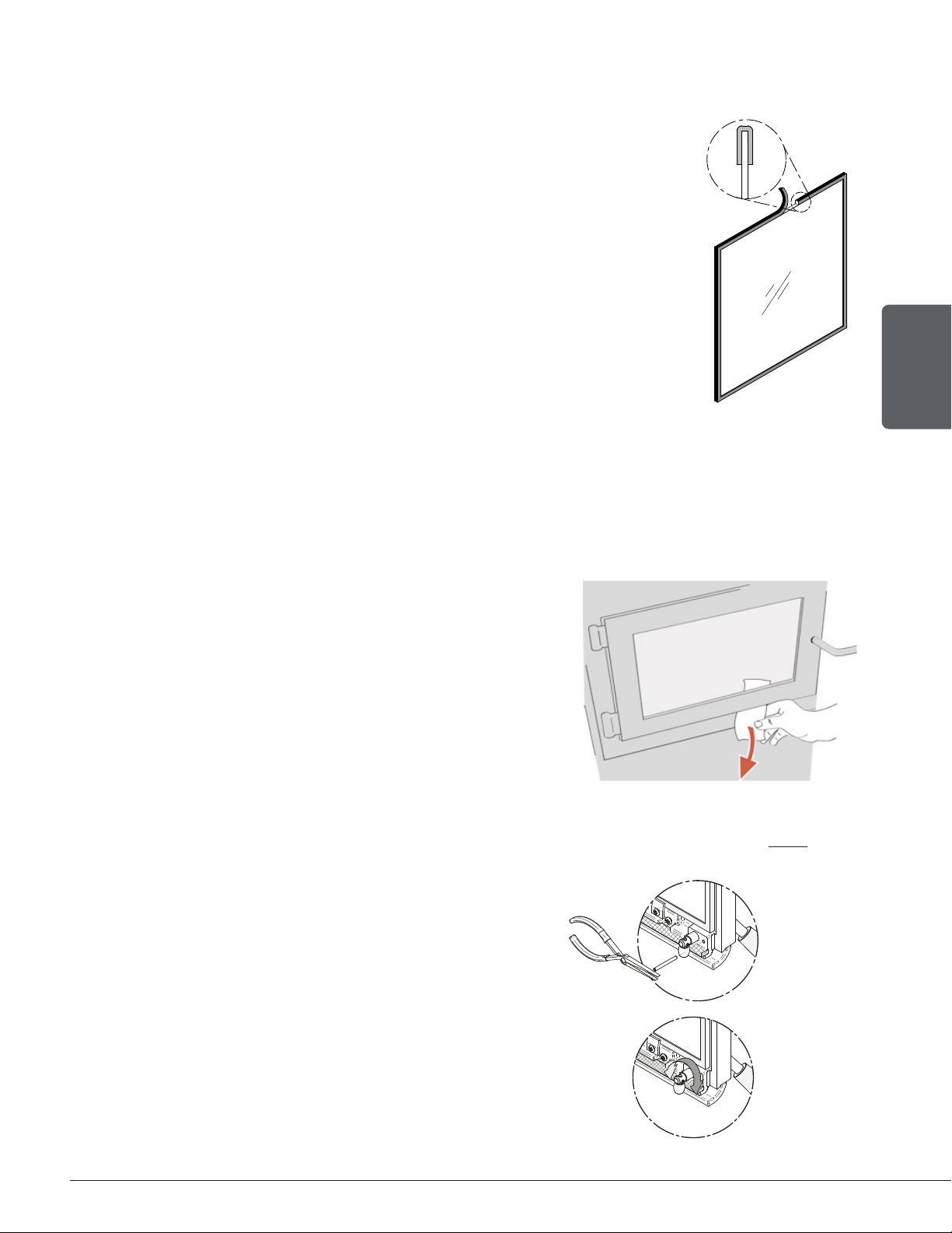
6.3.3 Gasket
The glass gasket is flat, adhesive-backed, woven fibreglass. The gasket must be centred on the
edge of the glass.
1. Follow the steps of the previous section to remove the glass.
2. Remove the old gasket and clean the glass thoroughly.
3. Peel back a section of the paper covering the adhesive and place the
gasket on a table with the adhesive side up.
4. Stick the end of the gasket to the middle of one edge, then press the
edge of the glass down onto the gasket, taking care that it is perfectly
centred on the gasket.
5. Peel off more of the backing and rotate the glass. The gasket must not
be stretched during installation.
6. Cut the gasket to the required length. Pinch the gasket onto the glass
in a U shape, all around the glass.
6.4 Door
In order for the fireplace to burn at its best efficiency, the door must provide a perfect seal with
the firebox. Therefore, the gasket should be inspected periodically to check for a good seal. The
tightness of the door seal can be verified by closing and latching the door on a strip of paper.
The test must be performed all around the door. If the paper slips out easily anywhere, either
adjust the door or replace the gasket.
At the end of each heating season it is recommended
to add a high temperature graphite paste on the
threads of the door handle. This paste wil protect the
threads from rust and prevent dust accumulation that
can prevent the handle from rotating freely.
6.4.1 Adjustment
The door seal may be improved with a simple latch mechanism adjustment on the door:
ENGLISH
1. Remove the split pin by pulling and turning
it using pliers.
2. Turn the handle one counterclockwise turn
to increase pressure.
Installation and Operation Manual - HE275CF
Page 25
Page 26
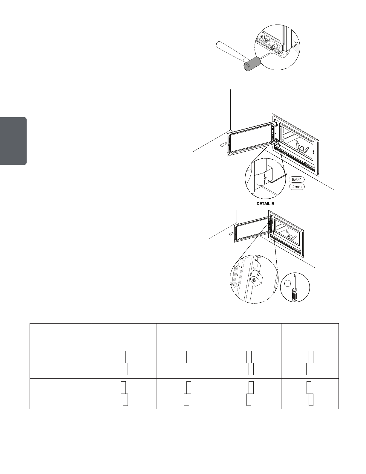
3. Reinstall the split pin with a small hammer.
Alignment
To align the doors, open the doors and slightly
unscrew the set screws on the lower and upper
door hinges with a 3/32» Allen key to release the
adjustable hinge rods.
ENGLISH
Using a flat screwdriver, turn the adjustable
hinge rods in the directions shown to adjust
the doors. Tighten the set screws on the door
hinges when they are in the desired positions.
Doors position
with more space
Top pintle
Doors position
with less space
Doors tilt up Doors tilt down
Bottom pintle
Page 26
Installation and Operation Manual - HE275CF
Page 27
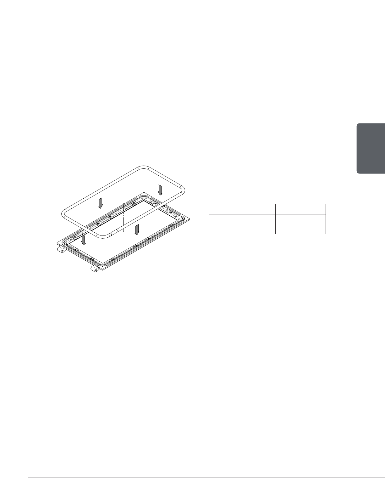
6.4.2 Gasket
It is important to replace the gasket with another having the same diameter and density to
maintain a good seal.
1. Remove the door and place it face-down on something soft.
2. Remove the old gasket from the door. Use a screwdriver to scrape the old gasket adhesive from
the door gasket groove.
3. Apply a bead of approximately 3/16» (5 mm) of high temperature silicone in the door gasket
groove. Starting from the middle, hinges side, press the gasket into the groove. The gasket must
not be stretched during installation.
4. Leave about ½» (10 mm) long of the gasket when cutting and press the end into the groove. Tuck
any loose fibers under the gasket and into the silicone.
5. Close the door. Do not use the fireplace for 24 hours.
ENGLISH
Location Dimensions
On door frame
82" long
Round 5/8"
Installation and Operation Manual - HE275CF
Page 27
Page 28
6.5 Exhaust System
Wood smoke can condense inside the chimney, forming a inflammable deposit called creosote. If
creosote builds up in the system, it can ignite when a hot fire is burned in the insert. A very hot fire
can progress to the top of the chimney. Severe chimney fires can damage even the best chimneys.
Smouldering, smoky fires can quickly cause a thick layer of creosote to form. When the insert is
operated properly, the exhaust from the chimney is mostly clear and creosote builds up more slowly.
«Creosote - Formation and Need to Removal
When wood is burned slowly, it produces tar and other organic vapors, which combine with
expelled moisture to form creosote. The creosote vapors condense in the relatively cooler
chimney flue of a slow-burning fire. As a result, creosote residue accumulates on the flue
lining. When ignited this creosote makes an extremely hot fire. The chimney connector and
chimney should be inspected at least once every two months during the heating season to
determine if a creosote buildup has occurred. If creosote has accumulated (⅛" [3mm] or
more it should be removed to reduce the risk of a chimney fire.
ENGLISH
6.5.1 Cleaning frequency
It is not possible to predict how much or how quickly creosote will form in the chimney. It is
important, therefore, to check the build-up in the chimney monthly until the rate of creosote
formation is determined. Even if creosote forms slowly in the system, the chimney should be
cleaned and inspected at least once each year. Establish a routine for the fuel, wood burner and
firing technique. Check daily for creosote build-up until experience shows how often you need
to clean to be safe. Be aware that the hotter the fire, the less creosote is deposited and weekly
cleaning may be necessary in mild weather even though monthly cleaning may be enough in the
coldest months. Contact your local municipal or provincial fire authority for information on how
to handle a chimney fire. Have a clearly understood plan to handle a chimney fire.
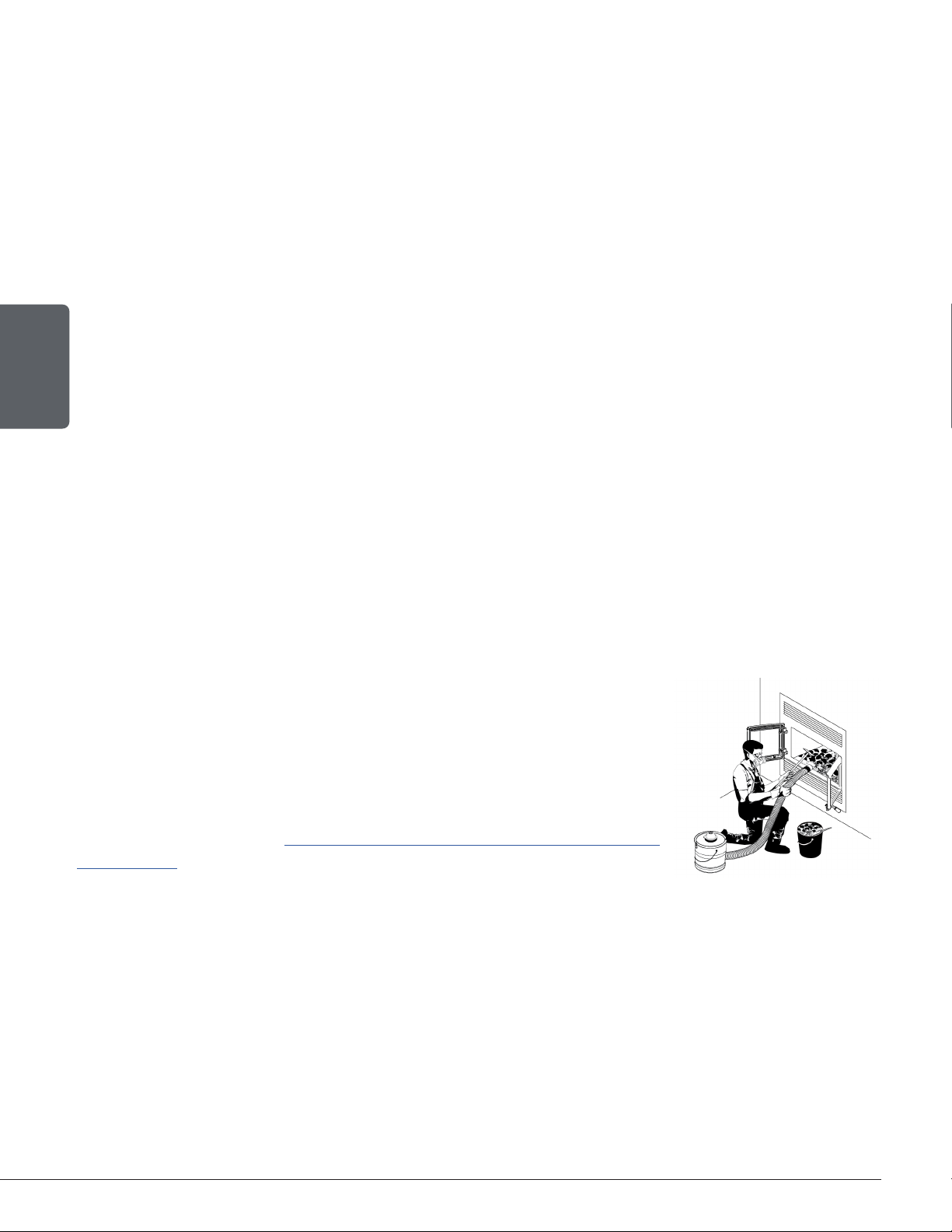
6.5.2 Sweeping the Chimney
Chimney sweeping can be a difficult and dangerous job. People
with no chimney sweeping experience will often prefer to hire a
professional chimney sweep to inspect and clean the system for the
first time. After seeing the cleaning process, some will choose to do
it themselves. The chimney should be checked regularly for creosote
buildup. Inspection and cleaning of the chimney can be facilitated by
removing the baffle. See «Appendix 7: Secondary Air Tubes and Baffle
Installation» for more details.
6.5.3 Chimney Fire
Regular chimney maintenance and inspection can prevent chimney fires. If you have a chimney
fire, follow these steps:
1. Close the fireplace door and the air intake control;
2. Alert the occupants of the house of the possible danger;
3. If you require assistance, alert the fire department;
4. If possible, use a dry chemical fire extinguisher, baking soda or sand to control the fire. Do not
use water as it may cause a dangerous steam explosion;
Do not use the appliance again until the fireplace and its chimney have been inspected by a
qualified chimney sweep or a fire department inspector.
Page 28
Installation and Operation Manual - HE275CF
Page 29

PART B – INSTALLATION
Install the fireplace only as described in these instructions and using only the following fireplace
components and chimney components from chimney manufacturers listed in «Table 4 : Approved
Chimneys».
• Fireplace;
• Traditional or modern gravity hot air distribution kit;
• Fresh air kit;
• Refractory panels;
• Insulated chimney made by the manufacturers listed in Table 4, with the corresponding specifications:
- Chimney lengths;
- Elbows (where necessary);
- Associated components as per these installation instructions.
Additional Equipment (optional)
• Finishing frame
• Forced air distribution kit;
• Fire Screen;
• Heat shield for combustible shelf.
ENGLISH
Installation and Operation Manual - HE275CF
Page 29
Page 30
7. Safety Information and Standards
7.1 Safety
• The fireplace and chimney must be in an enclosure up to the attic.
• CAUTION: DO NOT ATTEMPT TO MODIFY OR ALTER THE CONSTRUCTION OF
THE FIREPLACE OR ITS COMPONENTS. ANY MODIFICATION OR ALTERATION OF
CONSTRUCTION MAY VOID THE WARRANTY, LISTINGS AND APPROVALS OF THIS
SYSTEM. IN THAT CASE, STOVE BUILDER INTERNATIONAL (SBI) WILL NOT BE
RESPONSIBLE FOR DAMAGES. INSTALL THE FIREPLACE ONLY AS DESCRIBED IN
THESE INSTRUCTIONS.
• Mixing of appliance components from different sources or modifying components is prohibited
and will void the warranty. Any modification of the fireplace that has not been approved in
writing by the testing authority is prohibited and violates CSA B365 (Canada) and NFPA 211
(USA) standards.
ENGLISH
• The manufacturer grants no warranty, implied or stated, for
the poor installation or lack of maintenance of the fireplace
and assumes no responsibility for any consequential
damages.
• This fireplace must always be used with the original andirons.
• Do not use a fireplace insert and other products not specified
for use with this fireplace.
• Do not install in a mobile home (Canada) or manufactured home
(USA).
• Do not use materials other than those listed in the replacement parts section during installation as
they may be safety hazards and a fire could result.
• WARNING : THIS FIREPLACE HAS NOT BEEN TESTED WITH AN UNVENTED GAS LOG SET.
TO REDUCE THE RISK OF FIRE OR INJURY, DO NOT INSTALL AN UNVENTED GAS LOG
SET INTO THIS FIREPLACE.
7.2 Standards
When installed and operated as described in these instructions, this wood fireplace is suitable
for use in residential installations.
In Canada, the CSA B365 «Installation Code for Solid Fuel Burning Appliances and Equipment»
and the CSA C22.1 «Canadian National Electrical Code» are to be followed in the absence of
local code requirements.
In the USA, the ANSI NFPA 211 «Standard for Chimneys, Fireplaces, Vents and Solid FuelBurning Appliances» and the ANSI NFPA 70 «National Electrical Code» are to be followed in the
absence of local code requirements.
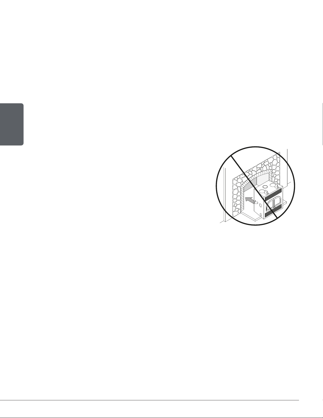
This fireplace is not approved for use with a so-called “positive flue connection” to the clay
tile of a masonry chimney.
Page 30
Installation and Operation Manual - HE275CF
Page 31
8. Fireplace Installation
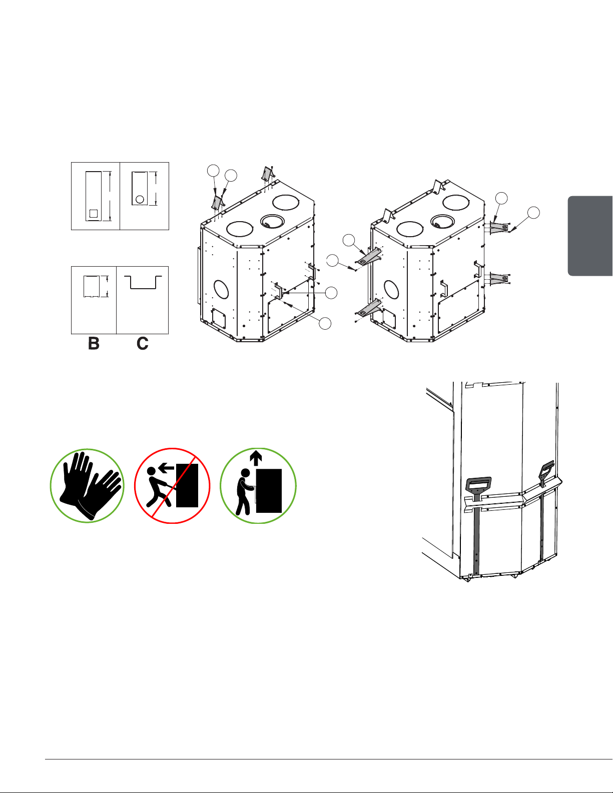
8.1 Standoff installation
In order to make an installation meeting the clearances to combustible materials around and
above the fireplace, it is required to install the spacers/stand-offs in the following locations; on
the top (B), on the sides ((D) and (E) 8 in total) and on the back of the fireplace (C). The spacers/
stand-offs and the screws (A) can be found in the fireplace manual. .
B
A
E
A
8"
203mm
5 1/2"
138mm
D
3 1/2"
87mm
E
D
A
C
A
8.2 Carrying Handles
To facilitate the transport of the fireplace, handles sold as an option
may be used. They are installed on each side of the fireplace. Wearing
gloves is strongly recommended when moving the fireplace.
ENGLISH
8.3 Location
The best location for the fireplace should consider the location of windows, doors, and circulation
in the room. There must be enough space in front of the fireplace for the hearth extension and
mantel and on the sides or back for the different heat distribution system, for the fresh air intake
and for the chimney. Ideally, the chimney must be able to pass through the house without the
need to cut floor joists or roof trusses.
Installation and Operation Manual - HE275CF
Page 31
Page 32
8.4 Clearances to combustibles
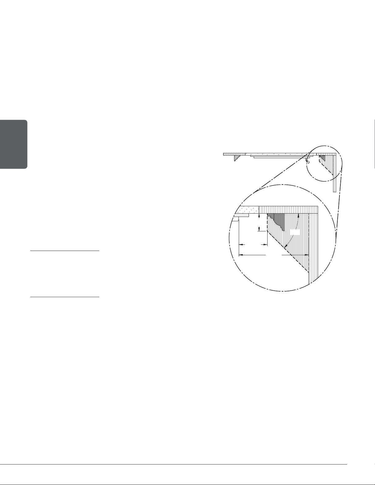
The clearances shown in this section have been determined by test according to procedures set
out in safety standards ULC S610 (Canada) and UL127 (U.S.A.). When the fireplace is installed
so that its surfaces are at or beyond the minimum clearances specified, combustible surfaces
will not overheat under normal and even abnormal operating conditions.
No part of the fireplace may be located closer to the combustible than the minimum
clearance given.
A material is considered non-combustible when made entirely of steel, iron, bricks, tiles,
concrete, slate, glass or a combination of these materials. Materials corresponding to ASTM
E136 and UL 763 are considered to be non-combustible materials with the exception of
gypsum, which will be considered a non-combustible material only if it is certified to withstand
an ambient temperature of use of 250°F and more.
− Maximum mantle depth 3" (76 mm)
ENGLISH
− Mantle minimum distance 8" (203 mm) (measured from
the door opening)
− Side wall distance 13" (330 mm) (measured from the door
opening)
− Minimum distance to the wall in front of the fireplace 48"
(122 cm)
− Minimum ceiling height : 76" (1,93 m) measured from the
base of the fireplace.
3"
76mm
45°
8"
Fireplace enclosure :
− Back wall : 0"
203mm
13"
330mm
− Sides : 0"
− Floor (underneath the fireplace) : 0"
−
Fireplace enclosure :
− Chimney : 2" (50 mm)
8.5 Framing construction
The frame, on the sides and back of the fireplace, must be made of 2"x 3" (5 cm x 8 cm) or
larger. The front studs as well as headers on top of the fireplace must be of a depth no more
than the depth of the top standoffs. The standoffs can be installed either flush with the fireplace
or setback of ½» depending on the thickness of the finishing material used.
Page 32
Installation and Operation Manual - HE275CF
Page 33
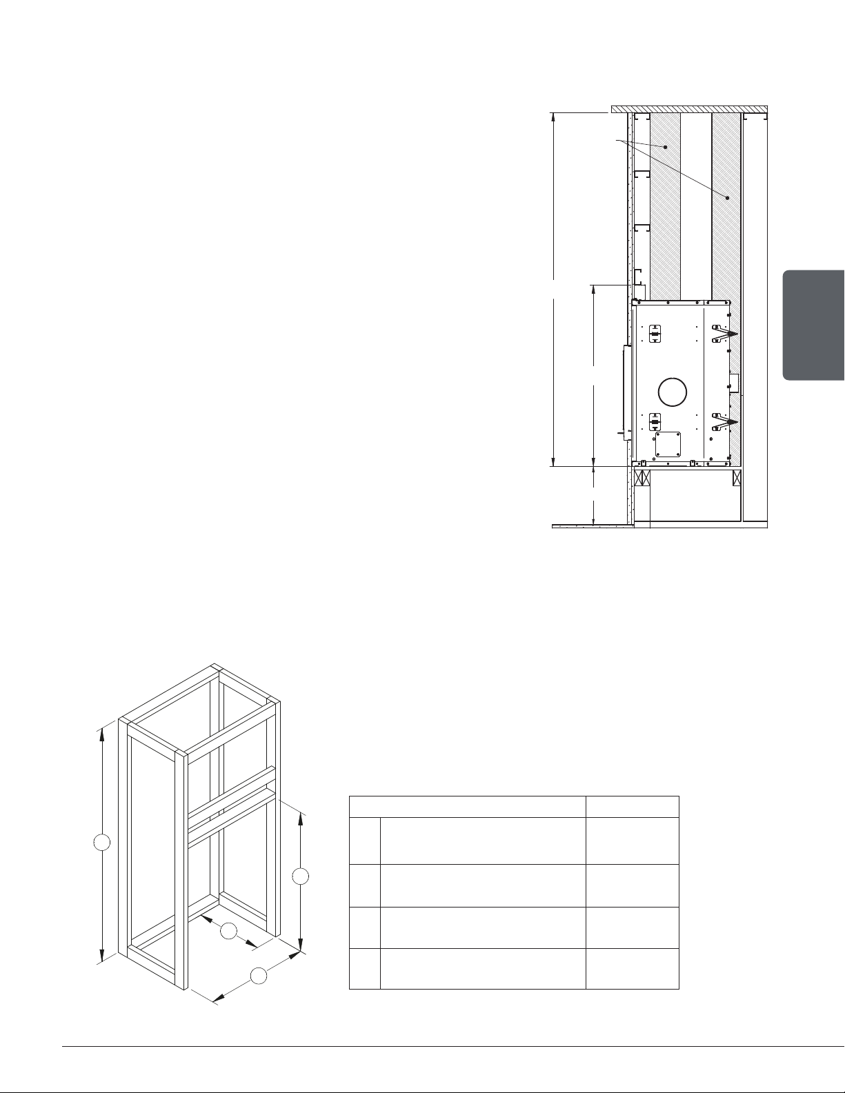
Do not use combustible materials for the frame directly above the fireplace. This area
should remain empty to a height of 76" (1.93 m) measured from the base of the fireplace.
Build the fireplace frame using vertical studs placed on the
sides of the fireplace, from the floor to the ceiling. The studs
must be set back from the front edge of the fireplace by a
space equivalent to the thickness of the finishing material,
CET ESPACE DOIT
RESTER VIDE
THIS SPACE MUST
REMAIN EMPTY
so that it is flush with the finish of the fireplace.
Headers between studs should be installed as follows:
− The headers must be 2» x 3» (5 cm x 8 cm) or 2» x 4» (5 cm x
10 cm). Do not put wood or other material in the area above
the fireplace.
76"
1930mm
− Install only the cripple studs needed to support the finishing
material and mantle.
WARNING : DO NOT FILL THE REQUIRED EMPTY
SPACE INSIDE THE ENCLOSURE WITH INSULATION
OR ANY OTHER MATERIAL.
The fireplace must not be in contact with any insulation or
loose filling material. Inside the chase, around the fireplace,
insulation should be covered with drywall panels or any
other finishing material except where non-combustible
material is required.
8.5.1 Fireplace Framing
Framing dimensions should be used as a reference only
If a finishing material is installed inside the enclosure, its
thickness must be added to the following measurements.
The chase can be constructed of combustibles
materials except for headers in gray.
41 5/8"
1058mm
VARIABLE
ENGLISH
D
C
A
Installation and Operation Manual - HE275CF
FP12R
A Framing width
B
Framing height to the first
B
header
C Framing depth
D Framing total height
51 ¼"
(1,3 m)
41 ⅝"
(1,05 m)
25"
(635 mm)
76"
(1,93 m)
Page 33
Page 34
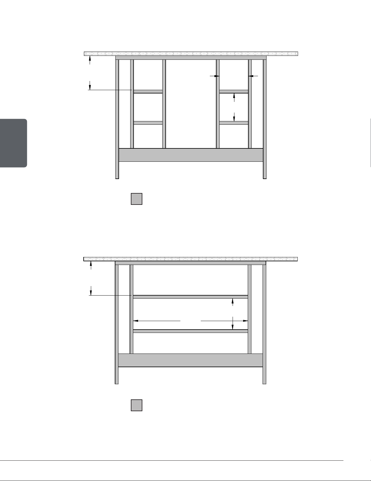
8.5.2 Framing of the gravity air distribution system
12"
305mm
MIN.
ENGLISH
Non combustible materials
8 1/4"
210mm
8 1/4"
210mm
Framing of the traditional style gravity air distribution system
12"
305mm
MIN.
8 1/2"
32 1/8"
816mm
216mm
Page 34
Non combustible materials
Framing the modern style gravity air distribution system
Installation and Operation Manual - HE275CF
Page 35
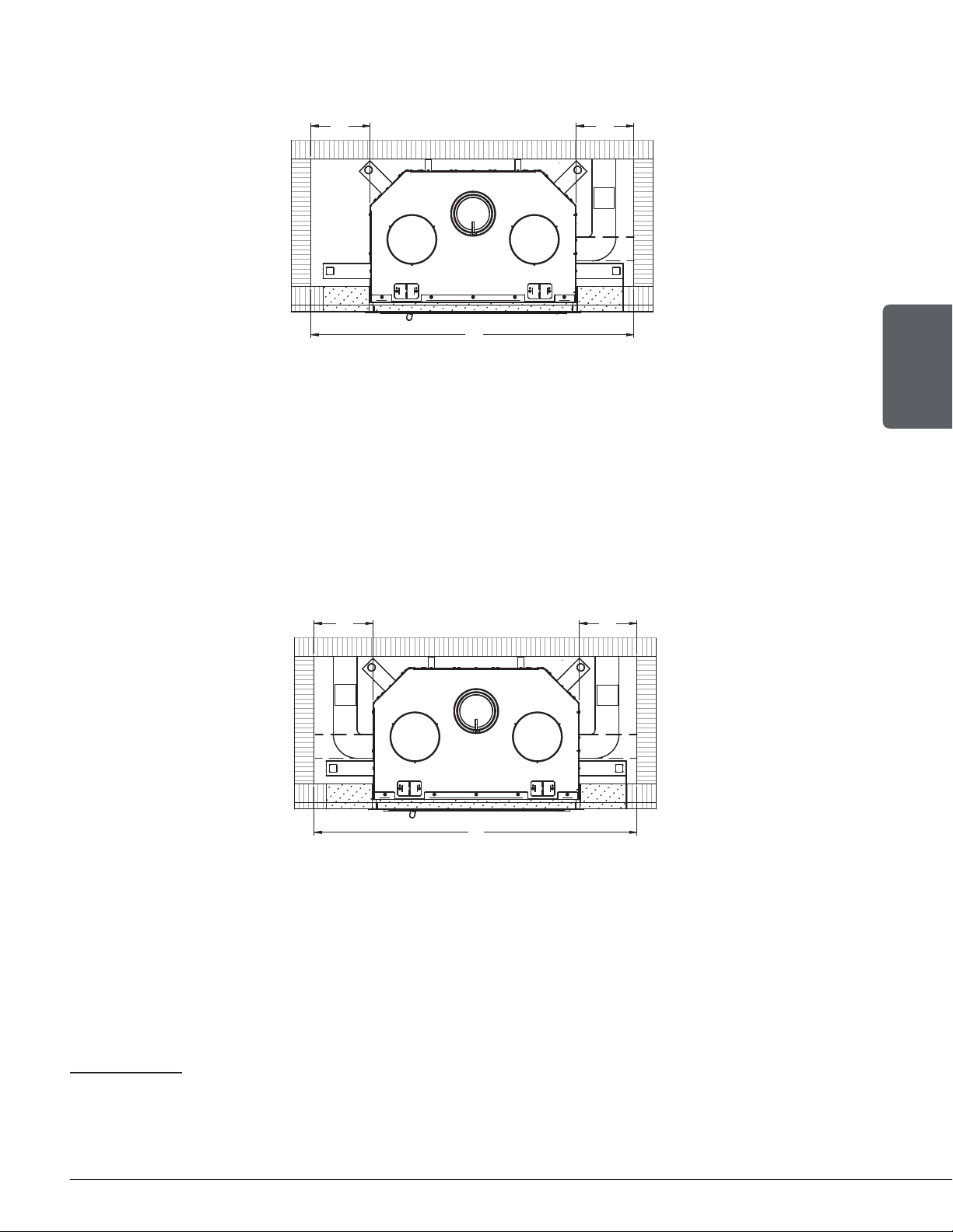
8.5.3 Framing with Fresh Air Intake
13
B
C
B
A
If a finishing material is installed inside the enclosure, its thickness must be added to the following
measurements.
14
A : Fresh air intake duct
(Fresh air intake can be installed on the right or underneath).
B : Distance between framing and side fireplace standoff 12" (305 mm)
C : Framing width (Installation with centered fireplace) 58 ¼" (1480 mm)
8.5.4 Framing with forced air distribution kit15
ENGLISH
E
D
F
E
D
If a finishing material is installed inside the enclosure, its thickness must be added to the following
measurements.
16
D : Forced air duct
(Duct can be installed on the left [recommended] or on the right).
E : Distance between framing and side fireplace standoff 18" (457 mm)
F : Framing width (Installation with centered fireplace) 70 ¼" (1784 mm)
13
Framing dimensions are for reference only. These measurements are recommended to prevent the ducts from being inside the standoff or have
too tight duct curves. Smaller dimensions can be used depending on the size and type of duct as well as the conguration of the installation.
14
HVAC duct, as per ULC S110 or UL 181, class 0 or class 1, must withstand temperatures up to 250F.
15
Framing dimensions are for reference only. These measurements are recommended to prevent the ducts from being inside the standoff or have
too tight duct curves. Smaller dimensions can be used depending on the size and type of duct as well as the conguration of the installation.
16
HVAC duct, as per ULC S110 or UL 181, class 0 or class 1, must withstand temperatures up to 250F.
Installation and Operation Manual - HE275CF
Page 35
Page 36
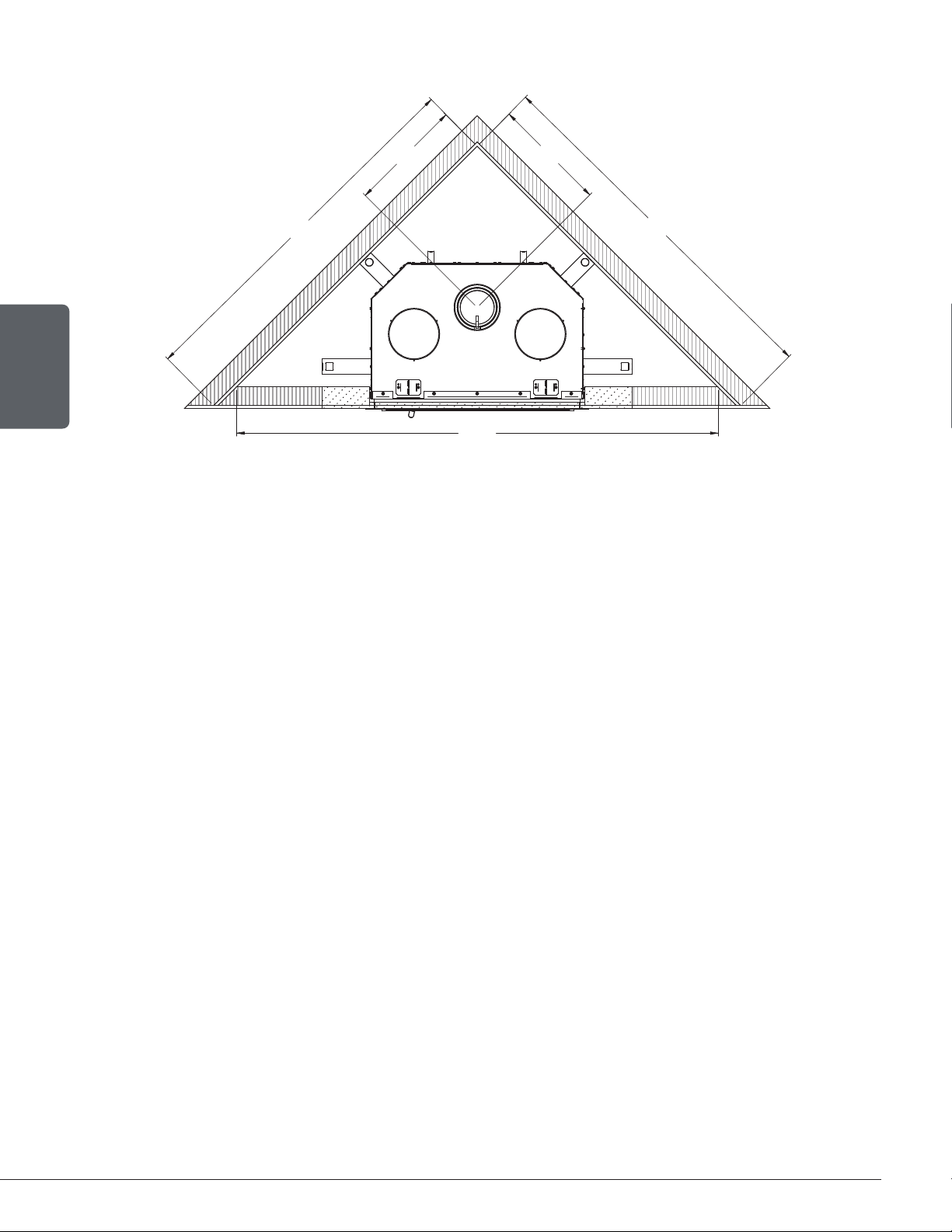
8.5.5 Framing with corner installation
18 1/2"
470mm
60"
1523mm
60"
1523mm
18 1/2"
470mm
ENGLISH
78 1/8"
1984mm
Framing configuration should be used as a reference only. If a finishing material is installed
inside the enclosure, its thickness must be added to the following measurements.
Theses values are minimum measurements and may need to be increased to allow the installation
of the fresh air intake, the forced air distribution or the type of finishing material used.
Page 36
Installation and Operation Manual - HE275CF
Page 37
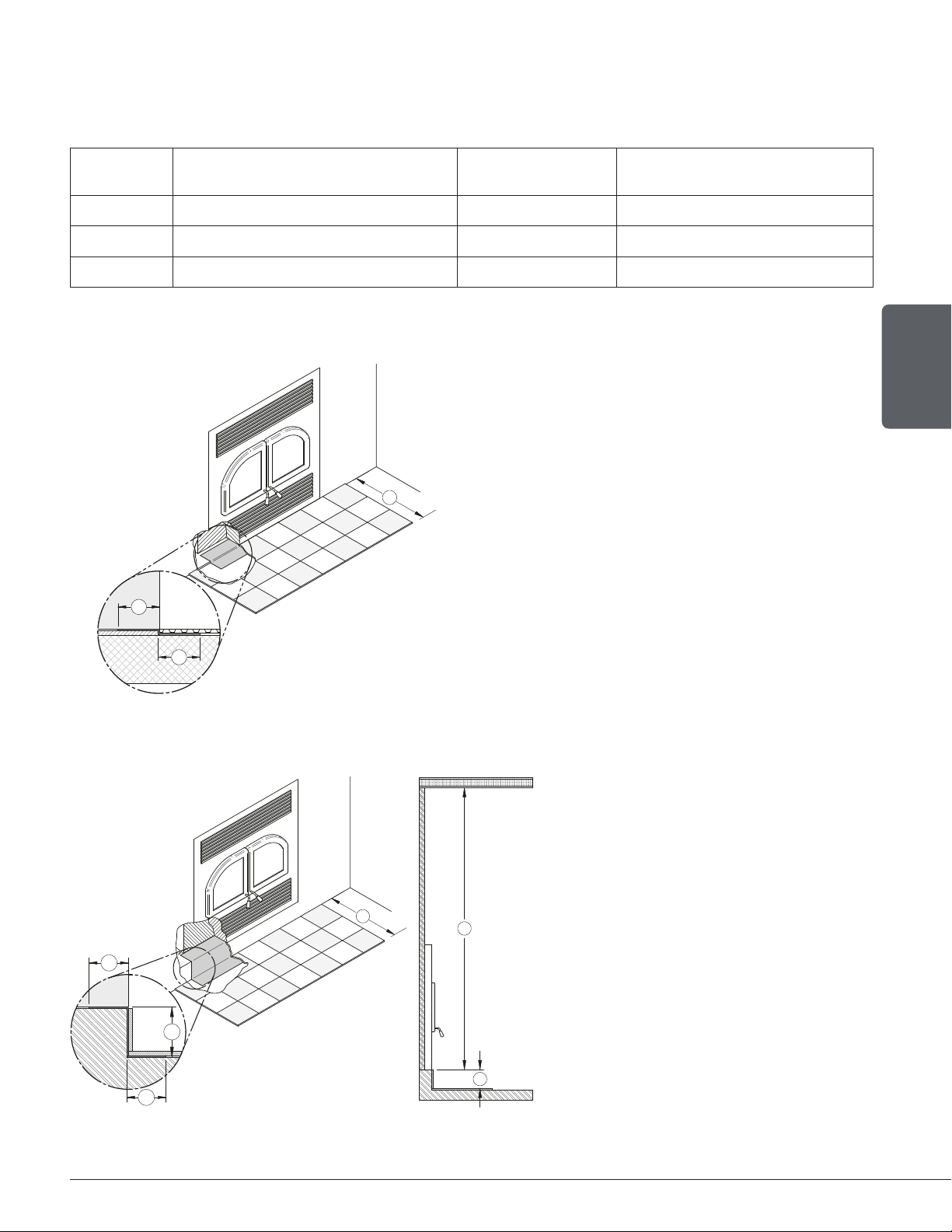
8.6 Hearth Extension Construction
This fireplace can be installed directly on the floor or on a raised base, combustible or not. The
installation can be done according to one of the following options :
OPTION INSTALLATION TYPE
R FACTOR
REQUIRED
NON COMBUSTIBLE FLOOR
PROTECTION DEPTH
#1 On floor level Yes (1.00) 16" (406 mm)
#2 Raised base of 4" or less Yes (1.00) 16" (406 mm)
#3 Raised base of more than 4" No 16" (406 mm)
8.6.1 Option #1 - Floor Level Installation
When the fireplace is installed directly on the floor,
a non-combustible floor protection of at least 16"
(A) with an R factor of 1.00 must be installed in
front of the fireplace.
The joint between the floor protection and the
A
D
fireplace must be protected over the entire width
of the floor protection by a folded and continuous
metal sheet (D = min 2" [51 mm]) (not supplied).
A clearance of 76" (1.93 m) between the base of
the fireplace and the ceiling must be respected.
ENGLISH
The minimum floor height under the fireplace
D
should match (or exceed) the height of noncombustible materials used for floor protection.
8.6.2 Option #2 - Raised Base Installation of 4" or Less
When the fireplace is installed on a
raised base of 4" or less (E), a noncombustible floor protection of at least
16" (A) with an R factor of 1.00 must
be installed in front of the fireplace.
A
D
E
D
F
E
The joint between the floor protection
and the fireplace must be protected over
the entire width of the floor protection
by a folded and continuous metal sheet
(D = min 2" [51 mm]) (not supplied).
It is recommended to make the sheet
metal in one piece.
A clearance of 76" (1.93 m) (F) between
the base of the fireplace and the ceiling
must be respected.
Installation and Operation Manual - HE275CF
Page 37
Page 38
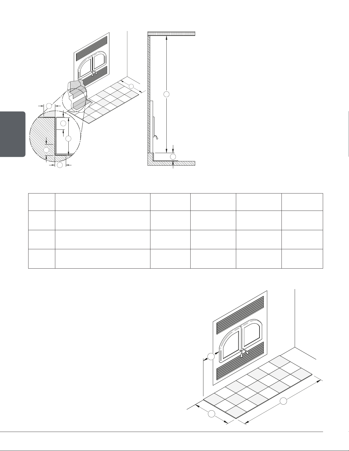
8.6.3 Option #3 - Raised Base Installation of More Than 4"
When the fireplace is installed on a
raised base of more than 4" (E), a
non-combustible floor protection of at
least 16" (A) with no R factor must be
installed in front of the fireplace.
A
D
D
E
ENGLISH
D
D
8.6.4 Floor Protection
OPTION INSTALLATION TYPE
#1 On floor level Yes (1.00)
#2 Raised base of 4" or less Yes (1.00)
F
E
R FACTOR
REQUIRED
The upper and lower angle, for the
full width of the floor protection, must
be protected by 2" horizontally and
vertically by a folded and continuous
metal sheet (D = 2" [51 mm])
(not supplied). The sheet metal does
not have to cover the rest of the wall
between the base of the fireplace and
the floor. A clearance of 76" (1.93 m) (F)
between the base of the fireplace and
the ceiling must be respected.
A B C
16"
(406 mm)
16"
(406 mm)
41 ½"
(1054 mm)
41 ½"
(1054 mm)
8"
(203 mm)
8"
(203 mm)
#3 Raised base of more than 4" No
16"
(406 mm)
41 ½"
(1054 mm)
8"
(203 mm)
Regardless of the installation type, there must be at least 8" (203 mm) on each side of the
fireplace door opening (C).
Floor protection must be a continuous
noncombustible surface such as ceramic, concrete
board, brick or other equivalent material approved
as floor protection. If the ceramic is used, it must
be placed on a continuous non-combustible panel
to prevent spills from being brought into contact
with the floor through cracks or gaps in the ceramic
slurry. Alternatives approved by the local building
C
code may also be used.
Do not leave carpets under the floor protection.
B
A
Page 38
Installation and Operation Manual - HE275CF
Page 39
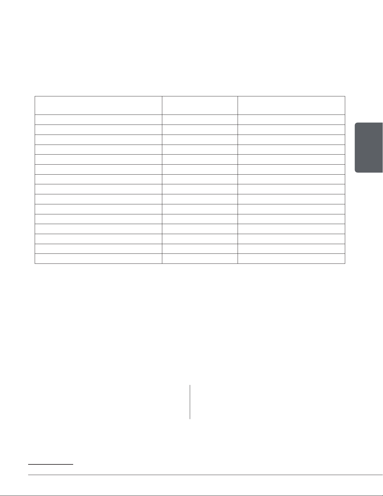
8.6.5 R Factor
There are two ways to calculate the R-value of the floor protection. First, by adding the R-values of
materials used, or by the conversion if the K factor and thickness of the floor protection are given.
To calculate the total R value from R values of the materials used, simply add the R-values of materials.
If the result is equal to or greater than the R-value requirements, the combination is acceptable.
R-values of some selected materials are shown below :
Table 2 : Thermal Characteristics of Common Floor Protection Materials
MATERIAL
CONDUCTIVITY (K)
PER INCH
RESISTANCE (R) PER INCH
THICKNESS
Micore® 160 0.39 2.54
Micore® 300 0.49 2.06
Durock® 1.92 0.52
Hardibacker® 1.95 0.51
Hardibacker® 500 2.3 0.44
Wonderboard® 3.23 0.31
Cement mortar 5.00 0.2
Common brick 5.00 0.2
Face brick 9.00 0.11
Marble 14.3 – 20.00 0.07 – 0.05
Ceramic tile 12.5 0.008
Concrete 1.050 0.950
Mineral wool insulation 0.320 3.120
Limestone 6.5 0.153
Ceramic board (Fibremax) 0.450 2.2
17
ENGLISH
Example:
Required floor protection R of 1.00. Proposed materials: four inches of brick and one inch of
Durock® board.
Four inches of brick (R = 4 x 0,2 = 0,8) plus 1 inch of Durock® (R = 1 x 0.52 = 0.52).
0.8 + 0.52 = 1.32.
This R value is larger than the required 1.00 and is therefore acceptable.
In the case of a known K and thickness of alternative materials to be used in combination,
convert all K values to R by dividing the thickness of each material by its K value. Add R values
of the proposed materials as shown in the previous example.
Common brick K value = 5
Thickness = 4"
R value = Thickness/K = 4/5 = 0.8
Durock K value =1.92
Thickness = 1"
R value = Thickness/K = 1/1.92 = 0.52
Total R value = .8 + 0.52 = 1.32
17
Information as reported by manufacturers and other resources
Installation and Operation Manual - HE275CF
Page 39
Page 40
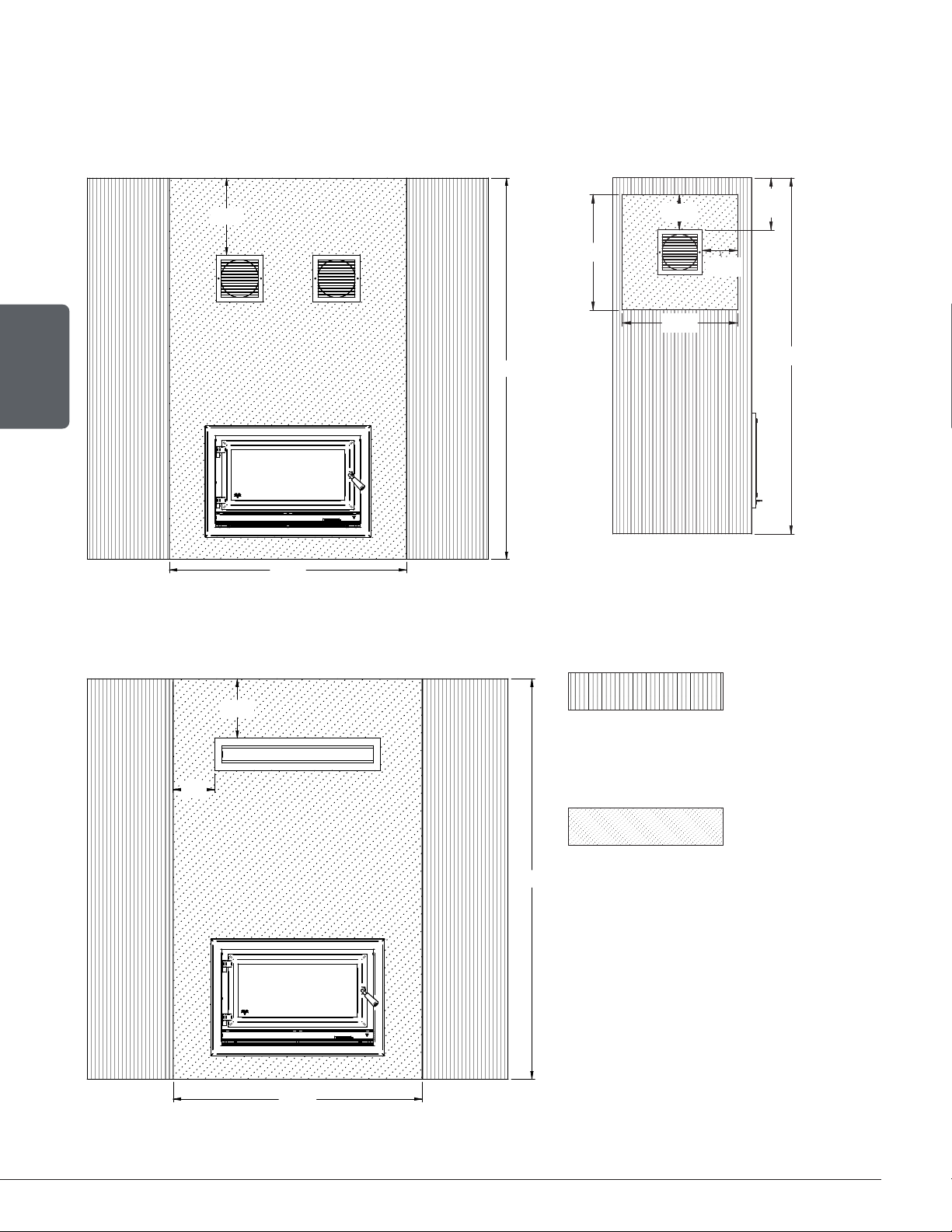
8.7 Facing
1276mm
Non combustible finishing materials such as brick or ceramic can be glued to the facade of the
fireplace. Do not put a seal between the faceplate and the finishing material to facilitate removal
of the facaplate, if necessary.
12"
8"
203mm
305mm
MIN.
1930mm
76"
12"
305mm
76"
1930mm
26"
660mm
8"
203mm
26"
660mm
ENGLISH
1 1/2"
38mm
12"
305mm
50 1/4"
1276mm
Front outlets Side outlets
Traditional style
Combustibles materials
allowed in this zone
Non combustible material
76"
1930mm
only in this zone
50 1/4"
Modern style
Page 40
Installation and Operation Manual - HE275CF
Page 41
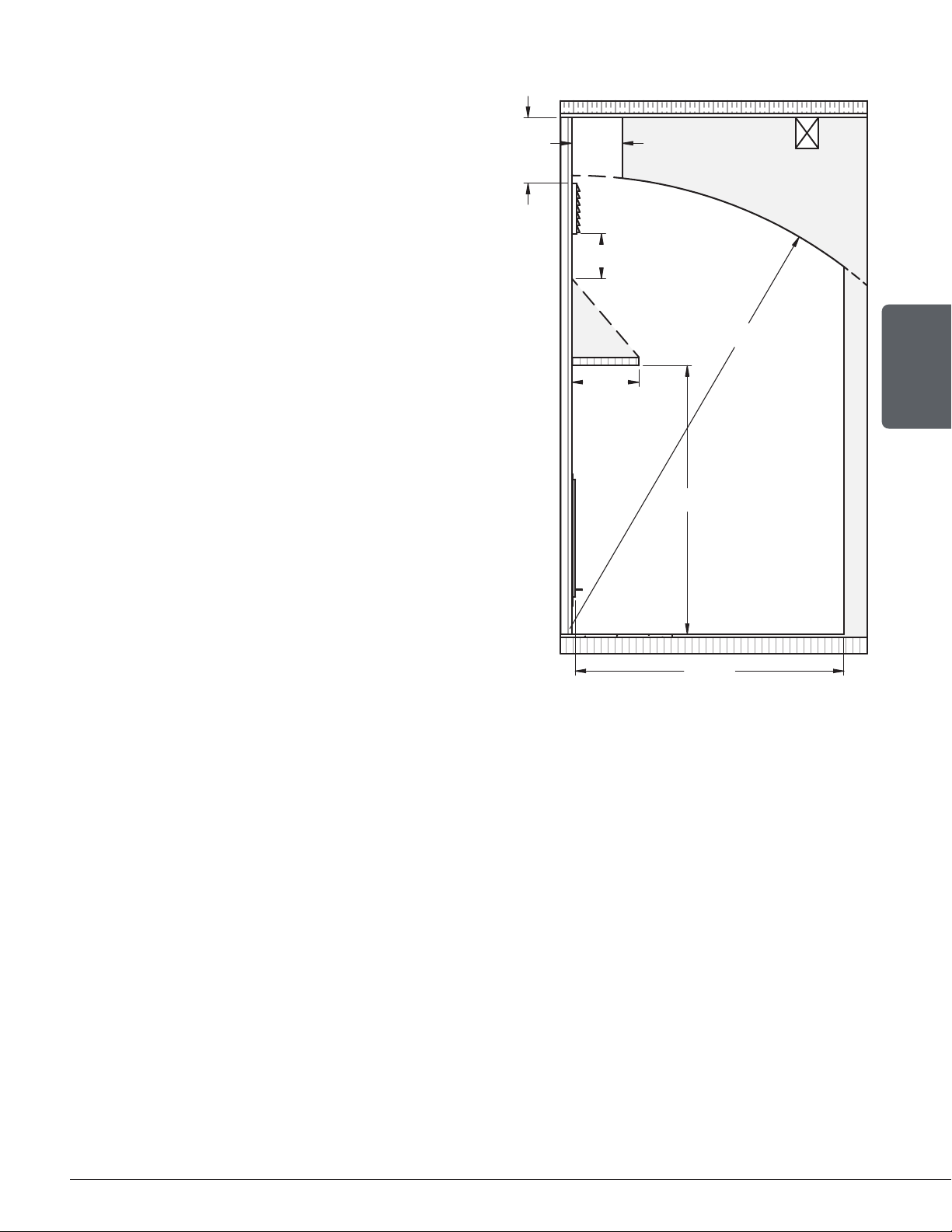
8.8 Combustible or non combustible Shelf Installation
1219mm
It is possible to install a combustible or a noncombustible shelf above the fireplace.
The shelf can be up to 12" (305 mm) deep and
must be installed at least 48" (1,22 m) from the
base of the fireplace.
In the illustration, non-combustible material is
allowed in the white area.
The shelf will be hot. Do not put combustible
materials on the shelf.
MIN.
12"
305mm
9"
229mm
8"
203mm
12"
305mm
48"
1219mm
76"
1930mm
ENGLISH
9. The Venting System
48"
The venting system acts as the engine that drives the wood heating system. Even the best
fireplace will not function safely and efficiently as intended if it is not connected to a suitable
chimney. The heat in the flue gases that pass from the fireplace into the chimney is not waste
heat. This heat is what the chimney uses to make the draft that draws in combustion air, keeps
smoke inside the fireplace and safely vents exhaust to outside. Heat in the flue gas can be seen
as the fuel the chimney uses to make draft.
9.1 Location
The location of the chimney is crucial for the proper functioning of the appliance. The chimney should
be installed within the house rather than up an outside wall and should rise straight up through
the tallest part of the house. This installation benefits from being enclosed within the warm
house environment, produce stronger draft, accumulate fewer creosote deposits and will be
unaffected by cold temperatures or harsh winds.
Outside chimneys will lead to cold back drafting when there is no fire in the fireplace, slow
kindling of new fires, and smoke roll-out when the door is open for loading.
It is important that the venting system has the right characteristics. A bad system can have
excessive draft, which can make the fire uncontrollable, creating very high temperatures in the
unit as well as in the chimney and seriously damaging them. A reddish glow on the unit and on
the chimney components indicates overheating. Excessive temperatures can cause a chimney fire.
Installation and Operation Manual - HE275CF
Page 41
Page 42
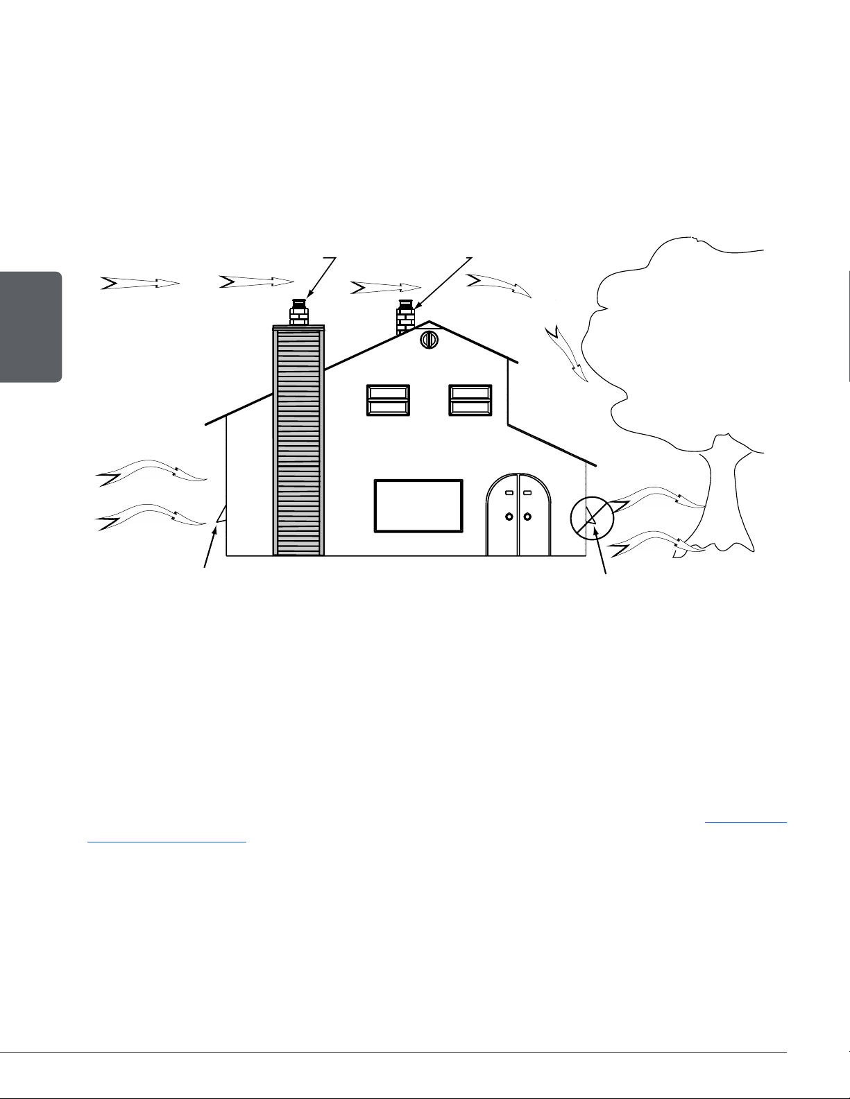
9.2 Supply of Combustion Air
du vent.
Emplacement
The safest and most reliable supply of combustion air for a fireplace is from the room in which
it is installed. Room air is already preheated so it will not chill the fire, and its availability is
not affected by wind pressures on the house. The only case in which the fireplace may not
have adequate access to combustion air is if the operation of a powerful exhaust device (such
as a kitchen range exhaust) causes the pressure in the house to become negative relative to
outdoors.
ENGLISH
Exposé au vent
Recommandé
Prise d’air extérieur
sur le côté exposé
au vent.
Emplacement
recommandé :
- Au-dessus du toit
recommandé :
- Au-dessus du toit
- À l’intérieur
Recommandé :
Cheminée extérieure
isolée pour les climats
plus froids.
Maison à étages
À l’abris du vent
Non recommandé
Prise d’air extérieur
sur le côté à l’abris
9.3 Chimney Installation
The chimney manufacturer’s installation manual takes precedence over the following installation
instructions. To ensure a safe installation, please refer to it. Some non-illustrated parts may be
required.
9.3.1 General Advices
• This wood burning fireplace has optimum performance and efficiency when connected to
a chimney with a 6" (150 mm) diameter flue, only the chimneys listed in the ««Table 4 :
Approved Chimneys» can be used.
• To insure a good draft, it is recommended to have a length of 18" (457 mm) from the top of
the unit to the first offset. However, starting using a 30° or 45° (Canada Only) elbow is also
approved.
• A CHIMNEY VENTING A FIREPLACE SHALL NOT VENT ANY OTHER APPLIANCE.
• The minimum height of the chimney system is 15 feet (4.6 m) from the base of the
appliance to the chimney cap. If only the minimum height of the chimney system is installed,
the operating conditions must be optimal (interior chimney, minimum height of 18" (457 mm)
before any deviation, etc.).
Page 42
Installation and Operation Manual - HE275CF
Page 43
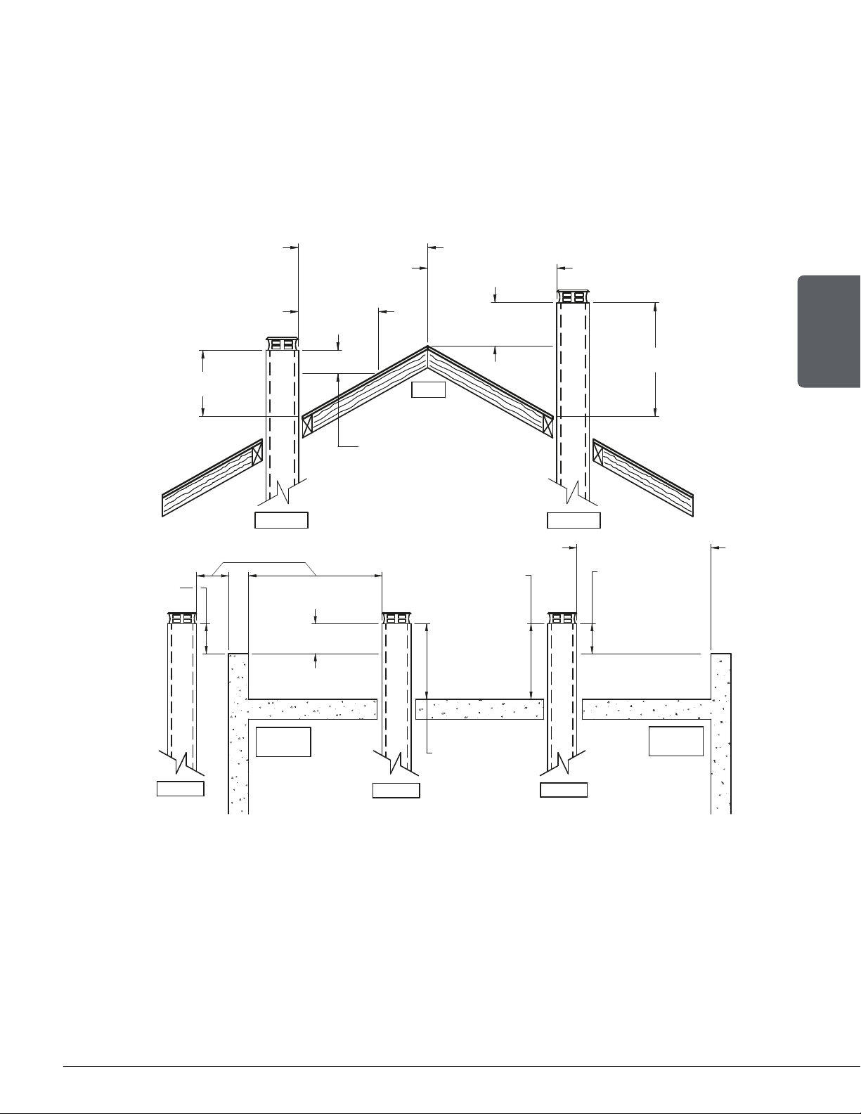
• The chimney must have at least one support. The maximum chimney length that should
be supported by the fireplace is 9 feet (2.75 m) for 2" Solid Pack chimney (5 cm) and 12 feet
(3.7 m) for 1" Solid Pack chimney.
• The chimney must extend at least 3 ft. (92 cm) above its point of contact with the roof and at
least 2 ft. (61 cm) higher than any wall, roof or building within 10 ft. (3.1 m) of it.
• WARNING : IF THE CHIMNEY IS INSTALLED IN A CHASE, IT MUST EXCEED THE TOP
OF IT BY AT LEAST 3 FEET (92 CM) IF IT’S MADE OF COMBUSTIBLE MATERIALS OR
AT LEAST 1.5 FEET (46 CM) WHEN IT IS MADE OF NON-COMBUSTIBLE MATERIALS.
MORE THAN 10' (3.1 M)
LESS THAN 10' (3.1 M)
CHIMNEY: 3' (0.92 M)
MINIMUM
2' (0.61 M)
MNIMUM
2' (0.61 M)
MINIMUM
CHIMNEY
LESS THAN 10' (3.1 M)
2' (0.61 M)
MINIMUM
10' (3.1 M)
2' (0.61 M)
MINIMUM
RIDGE
NOTE: HEIGHT ABOVE ANY
ROOF SURFACE WITHIN
10' (3.1 M) HORIZONTALLY
CHIMNEY: 3' (0.92 M)
MINIMUM
CHIMNEY: 3' (0.92 M)
MINIMUM
CHIMNEY
MORE THAN 10' (3.1 M)
NOTE: NO HEIGHT
ABOVE PARAPET
SHALL BE REQUIRED
WHEN DISTANCE
FROM WALLS OR
PARAPET IS MORE
THAN 10' (3.1 M)
ENGLISH
WALL OR
PARAPET
CHIMNEY
WALL OR
PARAPET
CHIMNEY
CHIMNEY: 3' (0.92 M)
MINIMUM
CHIMNEY
• Avoid deviations as much as possible, especially the sharp ones. Each deviation adds
restriction to the system and can lead to draft problems.
• If the chimney extends higher than 5 ft. (1.5 m) above its point of contact with the roof, it must
be secured using a roof brace.
• A rain cap must be installed on top of the chimney.
• Cut and frame square holes in all floors, ceilings, and roof that the chimney will go through to
provide a 2" (50 mm) minimum clearance between the chimney and any combustible materials.
Do not fill this 2" (50 mm) space with insulation or any other combustible material.
Installation and Operation Manual - HE275CF
Page 43
Page 44
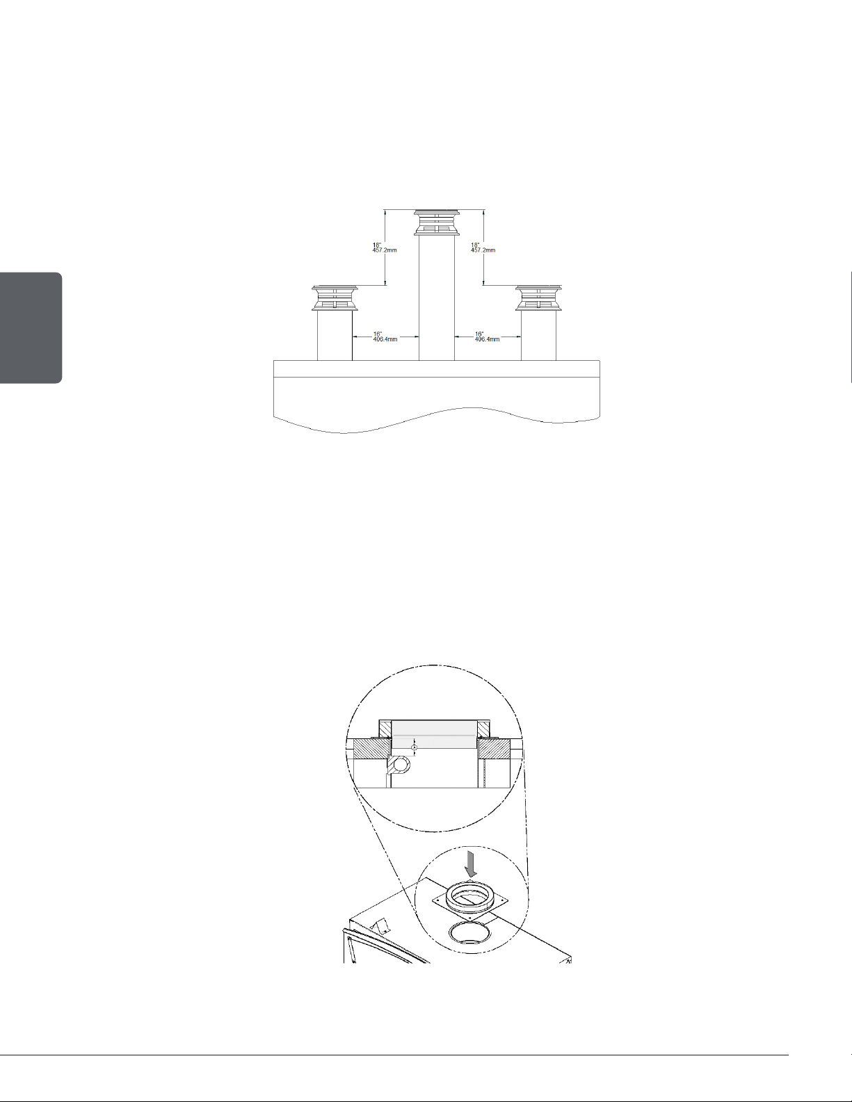
• A clearance of 2" (50 mm) between the chimney and any combustible material is required.
This space must remain free, without insulation or other combustible material.The parts of the
chimney that pass into inhabited spaces must be enclosed in an enclosure.
• For installations where more than one chimney is located in the same non-chase or within the
same area, their terminations must be separated by at least 16" (410 mm) horizontally, and
18" (460 mm) vertically. This separation is to prevent smoke migrating from one chimney to
another.
ENGLISH
• Cut and frame square holes in all floors, ceilings, and roof that the chimney will go through to
provide a 2" (50 mm) minimum clearance between the chimney and any combustible materials.
Do not fill this 2" space with insulation or any other combustible material.
• In all cases, the chimney must start with a 6" diameter anchor plate attached to the fireplace.
• If the male anchor plate nozzle exceeds 2" (50 mm) in length (A), it must be cut above the
lifting hooks welded inside the flue outlet so that it is sitting perfectly on the top of the
fireplace.
Page 44
Installation and Operation Manual - HE275CF
Page 45
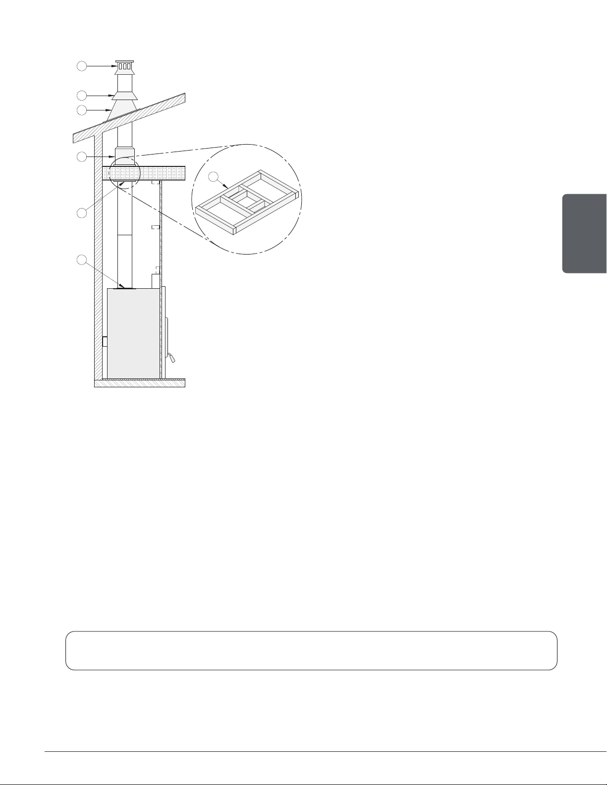
9.3.2 Ceiling Supported Installation
G
A : Anchor plate
B: Ceiling support
F
E
C: Framing opening
D: Attic insulation shield
D
C
E: Roof flashing
F: Storm collar
G: Chimney cap
B
A
ENGLISH
1. Cut and frame square openings (C) in the ceiling, floor and roof where the chimney will pass. A 2"
clearance must be maintained between the chimney and any combustible materials. The 2" space
must remain empty, without insulation or any other combustible material. The size of the floor and
ceiling holes must be in accordance with the chimney manufacturer’s instructions.
2. From underneath the ceiling, install a ceiling support (B) in each floor where the chimney will pass.
In the attic, install an attic radiation shield from above (D).
3. Install an anchor plate (A) and a first chimney section on the fireplace. Install the number of
chimney sections needed, making sure to lock each section in place.
4. When the desired height of the chimney is reached, install a roof support (not shown).
5. Put the roof flashing (E) in place and seal the joint between the roof and the flashing with roof
sealant. For sloping roofs, place the flashing under the upper shingles and on top of the lower
shingles. Nail the flashing to the roof, using roofing nails.
When a ventilated roof flashing is installed, precautions are to be taken not to caulk or seal the
ventilating openings.
6. Place the storm collar (F) on the roof flashing and tighten it with the bolt. Seal the joint between
the storm collar and the chimney, using silicone sealant.
7. Install the chimney cap (G).
Installation and Operation Manual - HE275CF
Page 45
Page 46
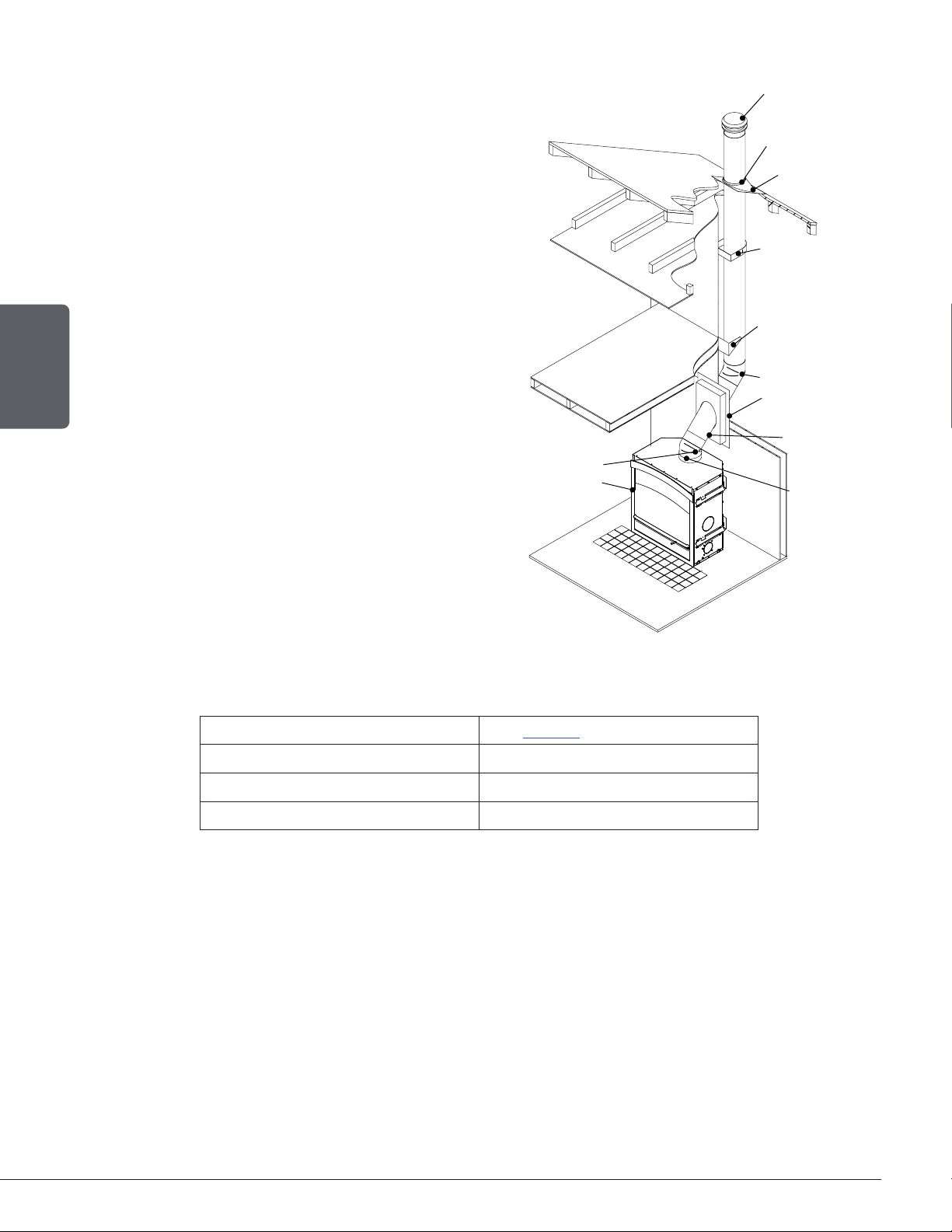
9.3.3 Offset Installation
1. Follow the instructions for a ceiling supported
installation until the first elbow.
2. Install and turn the elbow in the right direction.
Attach to the chimney using three ½" (12 mm)
metal screws.
3. Install the appropriate number of chimney
sections to obtain the necessary deviation.
Secure the chimney sections together with
three ½" (12 mm) screws. If the offset section
has two or more chimney sections, a bracket
must be installed. If the chimney go through a
wall, install a wall thimble.
4. Install another elbow to bring the chimney back
ENGLISH
in a vertical position.
5. Continue the installation following the
instructions of the ceiling supported installation.
ATTIC
1ST FLOOR
BASEMENT
ELBOW
FIREPLACE
RAIN CAP
STORM COLLAR
FLASHING
WALL BAND
OFFSET SUPPORT
ELBOW
INSULATED WALL
RADIATION SHIELD
CHIMNEY SECTION
CHIMNEY ADAPTOR
Table 3 : Minimum system height when using elbows
Chimney model See Table 4
Vertical Installation 15 ft (4,6 m)
Two (2) elbows 15 ft(4,6 m)
Four (4) elbows 17 ft (5,2 m)
9.3.4 Masonry Chimney Installation
The masonry chimney must meet the minimum requirements of the local building code or
equivalent for a safe installation. Contact a building inspector to learn about the requirements
in the area.
Before starting the installation, the masonry chimney should be inspected for cracks, crumbling
mortar, creosote layers, obstructions or other signs of deterioration. If signs of deterioration are
noted, the chimney should be repaired and cleaned before installation.
Page 46
Installation and Operation Manual - HE275CF
Page 47
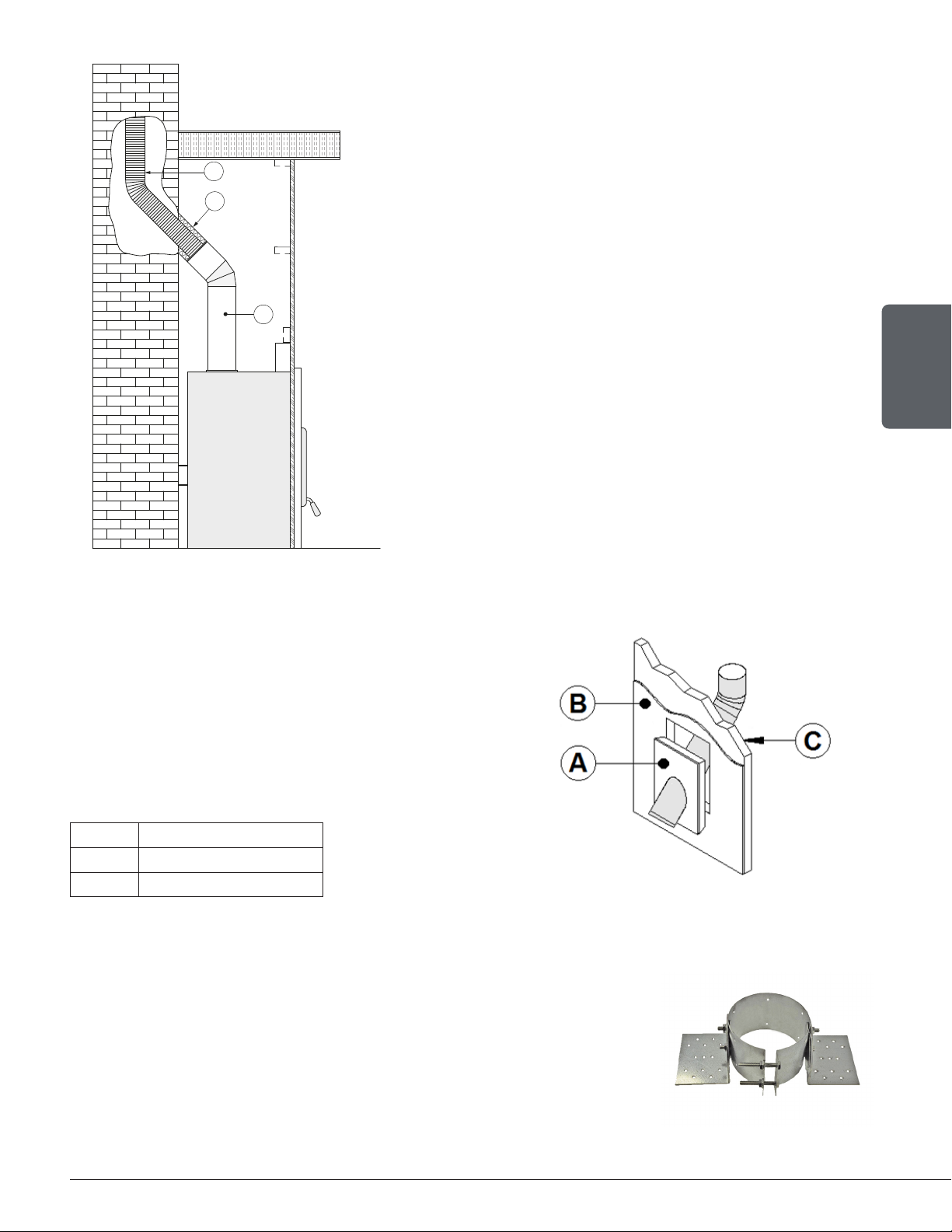
1. Position the fireplace in its location. Temporarily install
the elbow or chimney section (A) on the top of the
fireplace and, using a level, mark with an oval the
location where the flue liner will enter the masonry
chimney.
C
B
2. Mark where the flue will pass through the masonry
chimney. Drill a hole in the masonry chimney to insert
an insulated liner adapter (B).
3. Lower the liner (C) into the chimney to the level of the
hole.
A
4. Slide an insulated 45° or 30° liner adapter and connect
it to the liner.
5. Seal the opening around the liner with high temperature
refractory cement.
ENGLISH
6. Then, follow the chimney manufacturer’s instructions
to connect the extended liner section to the special
chimney connector.
The liner must extend at least 12" (30 cm) above the
masonry chimney.
9.4 Angled Wall Pass-Thru Installation
When passing through a combustible wall with the
chimney at a 30° or 45° angle (Canada only), an
angled wall pass-thru must be installed. Follow the
chimney manufacturer’s installation instructions.
In cold climate locations, it is recommended to
use the insulated wall pass-thru to maintain the
home’s thermal barrier.
A Wall pass-thru
B Interior wall
C Exterior wall
9.5 Chimney Support Installation
9.5.1 Roof Support
The universal roof support can be used on:
• a roof to support the chimney;
• a floor, ceiling, or roof over an offset to support the chimney or;
• as additional support.
Always follow the manufacturer’s instructions for the maximum chimney height that can be
supported by the support.
Installation and Operation Manual - HE275CF
Page 47
Page 48

9.5.2 Offset Support
This support is used above a chimney offset. When the offset of the chimney
pass through a wall, this support can be installed on the wall to support the
chimney.
9.6 Approved Chimneys
Table 4 : Approved Chimneys
CHIMNEY
MODEL TYPE DIAMETER
MANUFACTURER
Olympia Chimney
SBI Division Venting
ENGLISH
SBI Division Venting Nexvent 1" Solid Pack 6" (15 cm)
Olympia Chimney Champion Chimney System 1" Solid Pack 6" (15 cm)
Olympia Chimney Rockford Chimney Systems 1" Solid Pack 6" (15 cm)
Selkirk CF Sentinel (CF) 2" Solid Pack 6" (15 cm)
Selkirk Super Pro 2100 (ALT) 2" Solid Pack 6" (15 cm)
Selkirk Super Vent 2100 (JM) 2" Solid Pack 6" (15 cm)
Security Chimney S-2100 + 2" Solid Pack 6" (15 cm)
DuraVent Dura Tech 1" Solid Pack 6" (15 cm)
DuraVent Dura Tech Canada DTC 1" Solid Pack 6" (15 cm)
DuraVent DuraPlus HTC 2 "Solid Pack 6" (15cm)
Ventis 1" Solid Pack 6" (15 cm)
DuraVent Dura Tech Premium 2" Solid Pack 6" (15 cm)
DuraVent Dura Plus AC Triple Wall 6" (15 cm)
Metal Fab Temp Guard 1" Solid Pack 6" (15 cm)
American Metal HSS AC Triple Wall 6" (15 cm)
American Metal HS AC Triple Wall 6" (15 cm)
Page 48
Installation and Operation Manual - HE275CF
Page 49
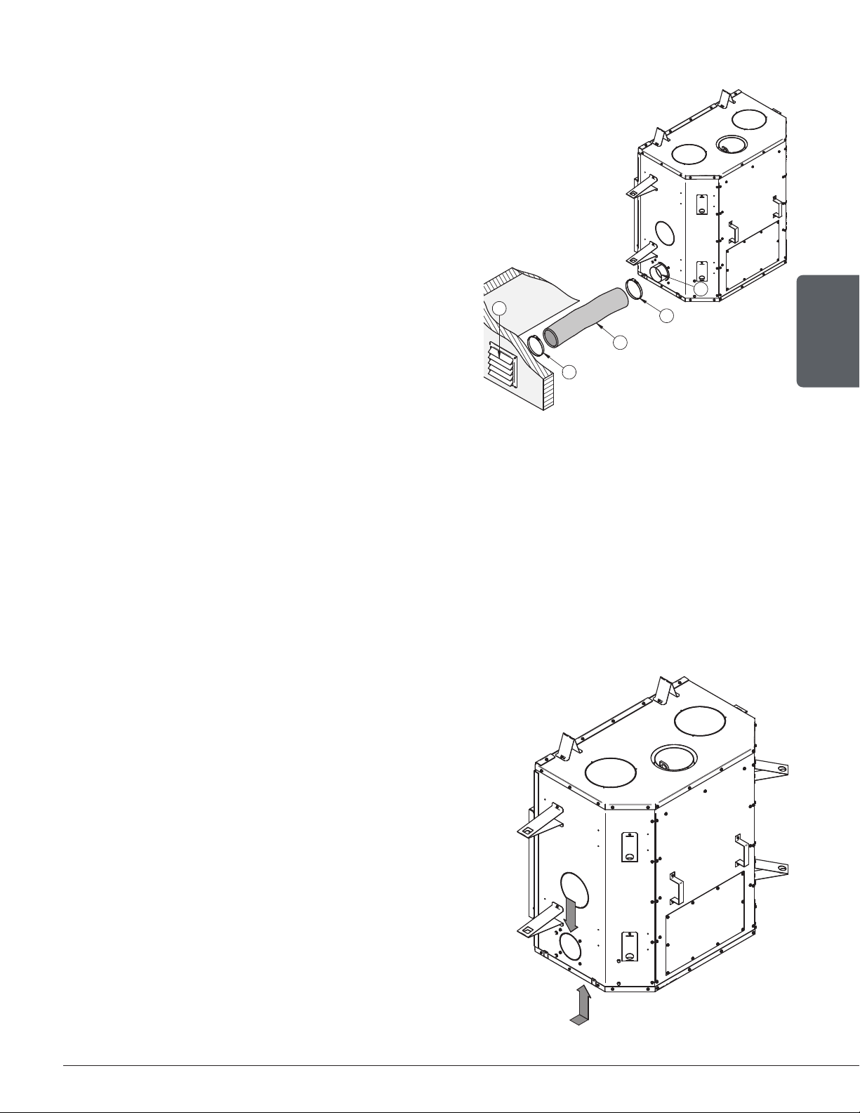
APPENDIX 1: INSTALLATION OF THE REQUIRED AIR INTAKE
2
• The air intake kit is mandatory and supply air must
either be taken directly outside the fireplace enclosure/
chase or outside the house.
• If the air inlet is installed in the room directly outside
the enclosure/chase, follow the steps illustrated in the
image below; No minimum pipe length is required with
this configuration.
• If the air intake comes from outside the house, also
follow the installation steps below;
• The insulated flexible pipe (D) should be of sufficient
length (at least 10’) and of a configuration to prevent
condensation.
• The outside wall register (E) must not be installed:
- More than 50% of the total height of the chimney;
- At more than 10’ (3 m) above the base of the
replace;
- More than 3’ (0.9 m) below the base of the replace
E
D
C
B
C
ENGLISH
• The fresh air must come from outside the house. The air intake should not take air in the attic,
basement or garage.
• The duct and the air intake can be installed above or below the floor level.
• The air intake should be installed high enough not to be obstructed by snow. It should be protected
from the wind, away from automobile exhaust, a gas meter or other air inlets or outlets.
The following items are included with the fireplace:
- One (1) 4» (76 mm) adapter (B);
- One (1) air intake plate;
- Four (4) screws.
The following items are not included:
- The outside wall register (E);
- The two (2) adjustable collars (C);
- Insulated duct length 4» (D). (Duct must be
HVAC type and must comply with ULC S110 or
UL 181, Class 0 or Class 1 and must withstand
temperatures up to 250° F).
Note: Only remove the knockout that will be used to
connect the fresh air intake assembly.
The fresh air intake can be installed in two different
1
locations on the fireplace. On the right side (1) of
the fireplace (the most common) or on the right side
under the fireplace (2).
Installation and Operation Manual - HE275CF
Page 49
Page 50
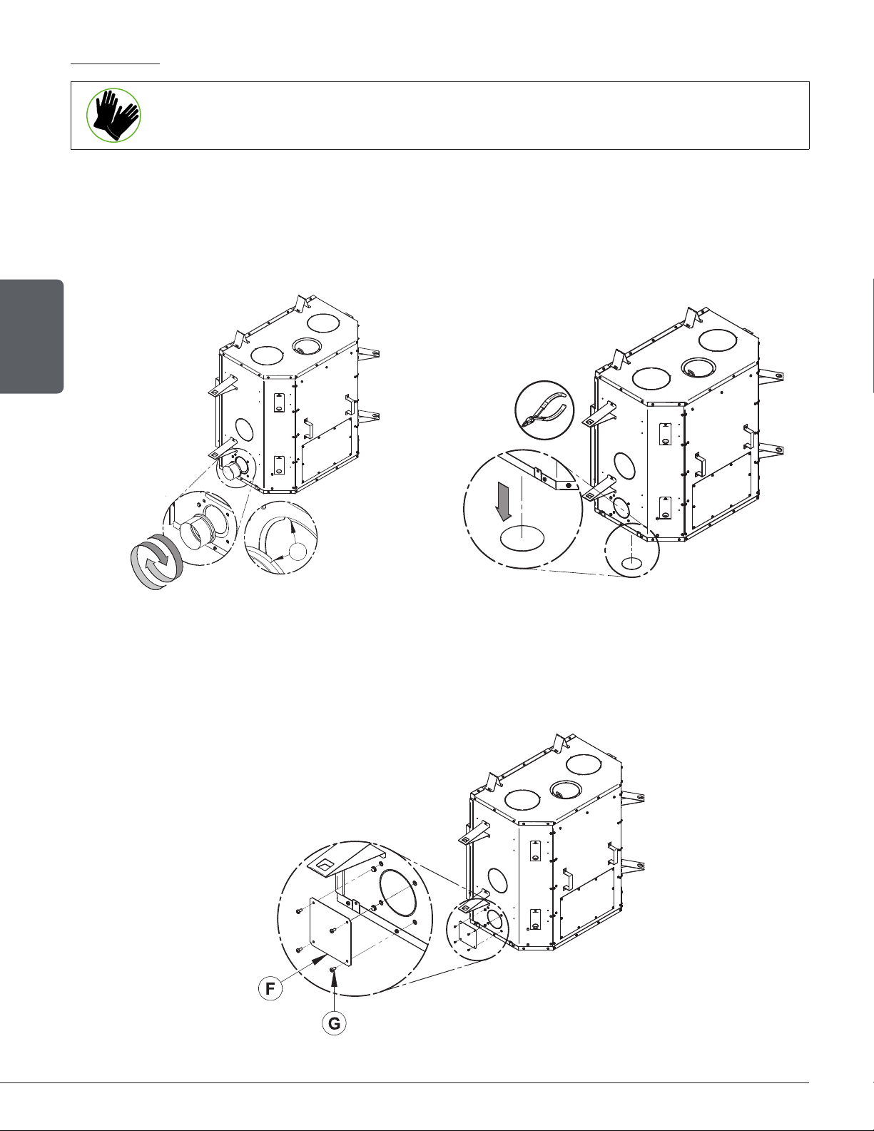
Installation
It is strongly recommended to wear gloves to complete the installation.
1. To use the air intake on the right side, remove the knockout by cutting the micro-joints. Cut and
remove the insulation and the other knockout inside the fireplace. To use the opening under the
fireplace, only cut the knockout.
2. Install the adapter included in the fireplace and align the notch of the adapter (T) with the one on
the fireplace. Turn the adapter clockwise.
ENGLISH
T
Fresh air intake on the right side Fresh air intake underneath
3. If the air inlet installation is below the appliance, install the plate (F) with the supplied screw (G)
on the opening on the right side of the appliance. The plate (F) and screws (G) are in the user
manual.
Page 50
Installation and Operation Manual - HE275CF
Page 51
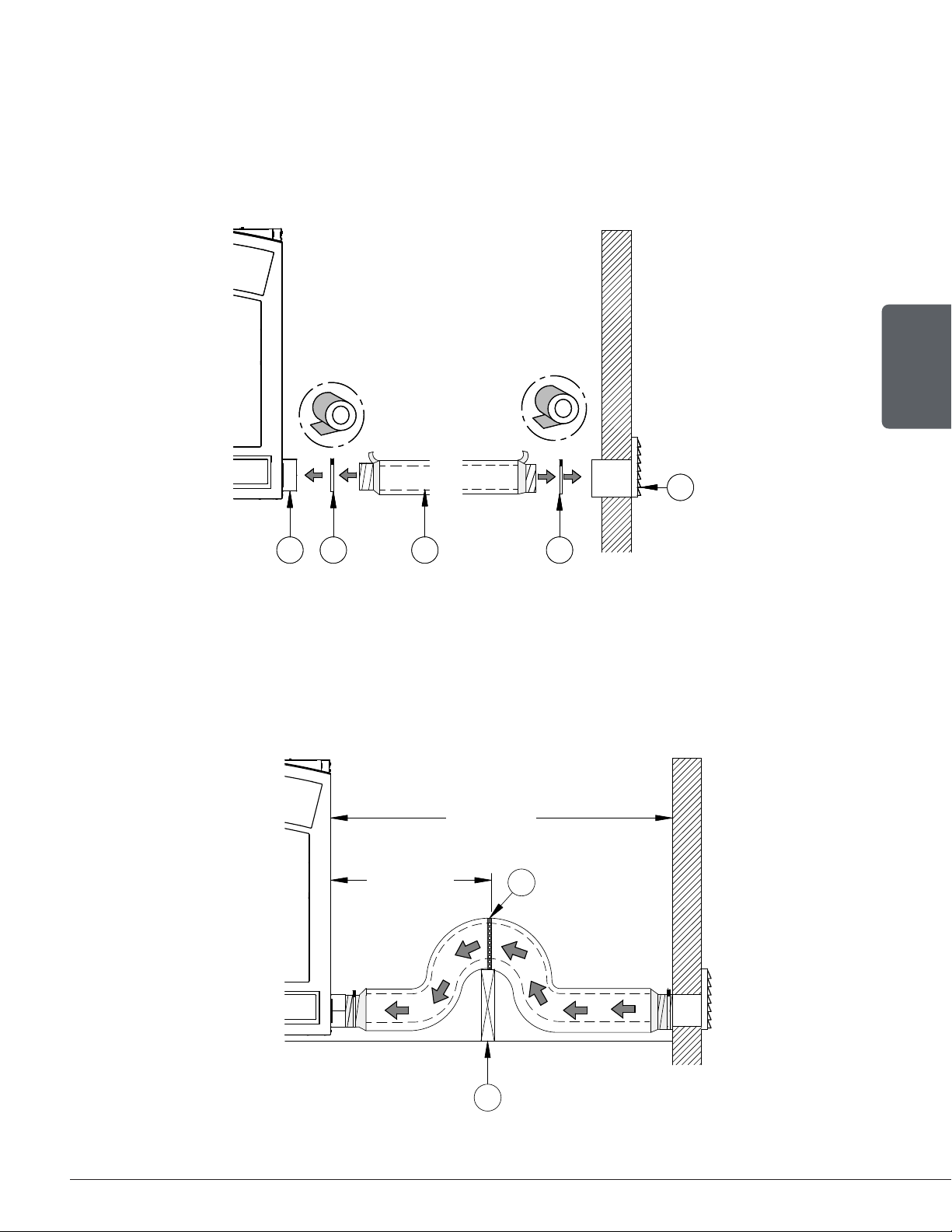
4. Install the flexible duct (D) on the fresh air inlet adapter (B) using one hose clamp (C). Fix the
other end to the outer wall register (E) using the second hose clamp (C). The outer wall register
(E) must be installed outside the house.
To properly install the flexible duct, gently remove the insulation and plastic wrap to expose
the duct. Fix the duct using clamps. Stick aluminum tape around the joint between the duct
and adapter to make the connection airtight. Carefully replace the insulation and plastic wrap
on the duct. Secure the plastic with aluminum tape.
E
E
ENGLISH
B C D C
B C D C
5. To complete the installation, make a hole of ¼" to ½" (6 mm to 13 mm) bigger than the duct
diameter on the outside wall of the house at the chosen location. From outside, place the outside
wall register in the hole (open side down) and fasten the register to the wall, with screws.
Use the required length for the installation while respecting the maximum length of 30'
(9 m). To avoid condensation, it is recommended to use an insulated duct long enough and
containing a «P-Trap» loop. This configuration can be done inside the chase, but must at all
times maintain clearances to combustibles.
MIN 10 pi
MAX 3 pi
F
G
It is strongly recommended to install a mechanical shutter that closes the outside air inlet
when the fireplace is not in use.
Installation and Operation Manual - HE275CF
Page 51
Page 52
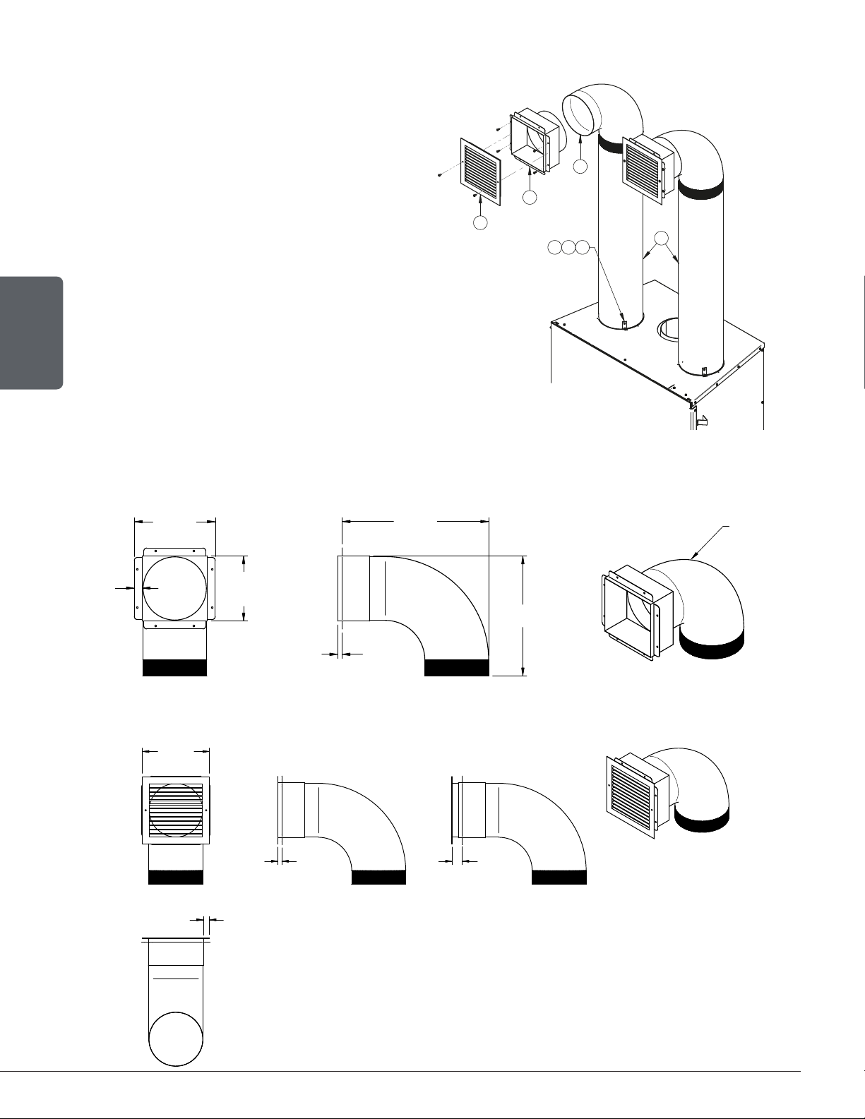
APPENDIX 2: OPTIONAL TRADITIONAL GRAVITY HOT AIR DISTRIBUTION
10"
KIT INSTALLATION
The kit includes:
− 2 hot air outlets (grilles (A) and frames (B));
− 2 90 elbows (C);
− 6 steel brackets (D) with fastening screws
(E) and self-tapping screws (F)
Parts not included in the kit:
− 8" rigid ducting (G), 26 ga, galvanized steel.
ENGLISH
Dimensions of hot air outlet frame with elbow
10 1/4"
259mm
TYP.
18 1/2"
468mm
C
B
A
FED
G
8"
O
204mm
1"
25mm
TYP.
8 1/4"
208mm
TYP.
5/8"
14mm
Dimensions of hot air outlet decorative grille with elbow
254mm
TYP.
5/8"
14mm
MIN.
7/8"
23mm
TYP.
2"
38mm
MAX.
15 1/8"
383mm
Page 52
Installation and Operation Manual - HE275CF
Page 53
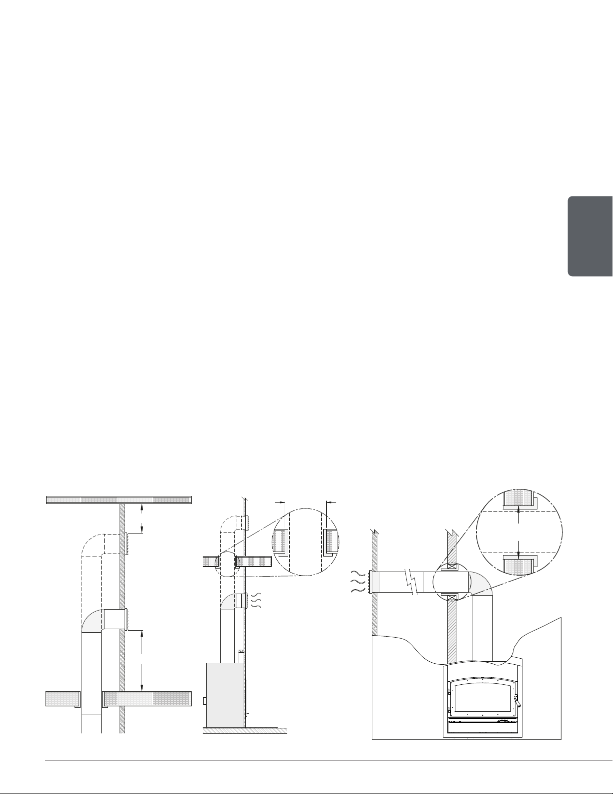
Installation rules and advices
• The minimum height of the hot air duct is 68" (1.7 m). It must be measured from the base of the
fireplace to the top of the hot air outlets.
• Do not connect the hot air ducts to a central heating system. The malfunction of the heating system
would overheat the fireplace.
• Do not use insulated flexible ducts as they may overheat.
• Do not use «T» fittings or anything other than those listed below.
• All ducts must be placed vertically or horizontally. Never route the ducting downwards.
• The flaps of the hot air outlet grills must point down to prevent overheating of the adjacent ceilings.
• Always install both hot air outlet grilles when the gravity air distribution kit is installed.
• The hot air outlets can be installed in the same room as the fireplace, or both can be installed in
adjacent rooms or upstairs. If the outputs are installed at different heights, the higher output will
draw more heat.
• When forced air kit is installed in conjunction with a gravity kit, the forced air device will draw some
of the air from the gravity kit ducting, therefore reducing its efficiency.
ENGLISH
Clearances
• Maximum length of pipes including elbows: 10' (3 m)
• The maximum number of elbows allowed per duct is two.
• There shall be a clearance of at least 12" (305 mm) between the hot air outlet frame and a ceiling,
side wall or mantel made of flammable material.
• When the duct passes through a wall or floor made of flammable material, a firestop radiation shield
(same as the one used for a class A chimney) must be installed in the opening of the wall or floor.
There must be a clearance of at least 2" (50 mm) between the ducts and the firestop.
13" X 13"
330mm X 330mm
12" MIN.
13" X 13"
330mm X 330mm
12" MIN.
Installation and Operation Manual - HE275CF
Page 53
Page 54
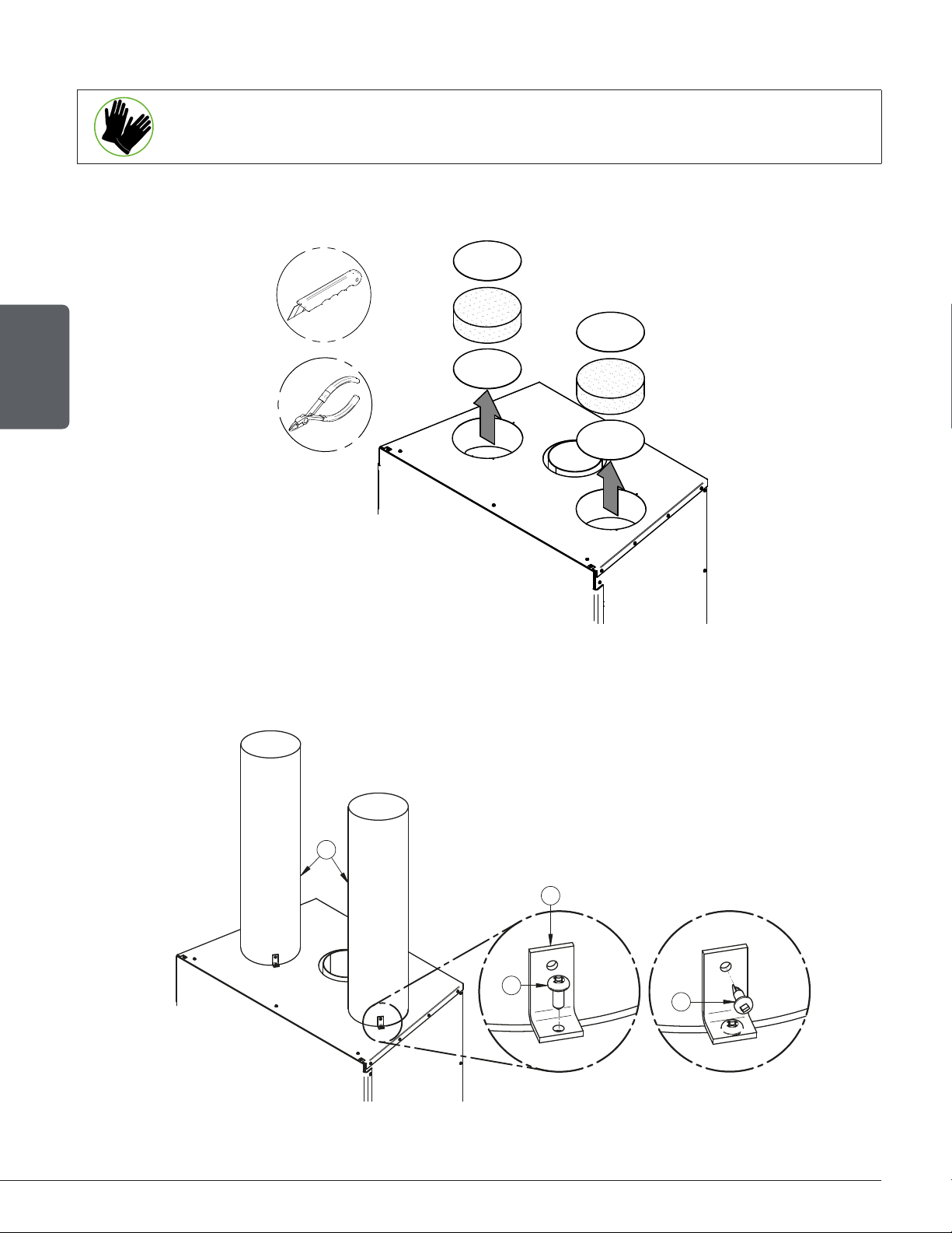
Installation
It is strongly recommended to wear gloves to complete the installation.
A) Remove the knockouts that close the 8" (20 cm) diameter holes on top of the fireplace. Then cut
and remove the insulation and the other set of knockouts inside the fireplace.
ENGLISH
1
2
B) Screw the 6 steel brackets (D) with 6 screws (E) onto the top of the fireplace (3 per duct). Insert
the ducts (G) (not supplied) into each opening and screw in place in the brackets (D) with 6 selfdrilling screws (F).
G
D
1
E
6X
2
F
6X
Page 54
Installation and Operation Manual - HE275CF
Page 55
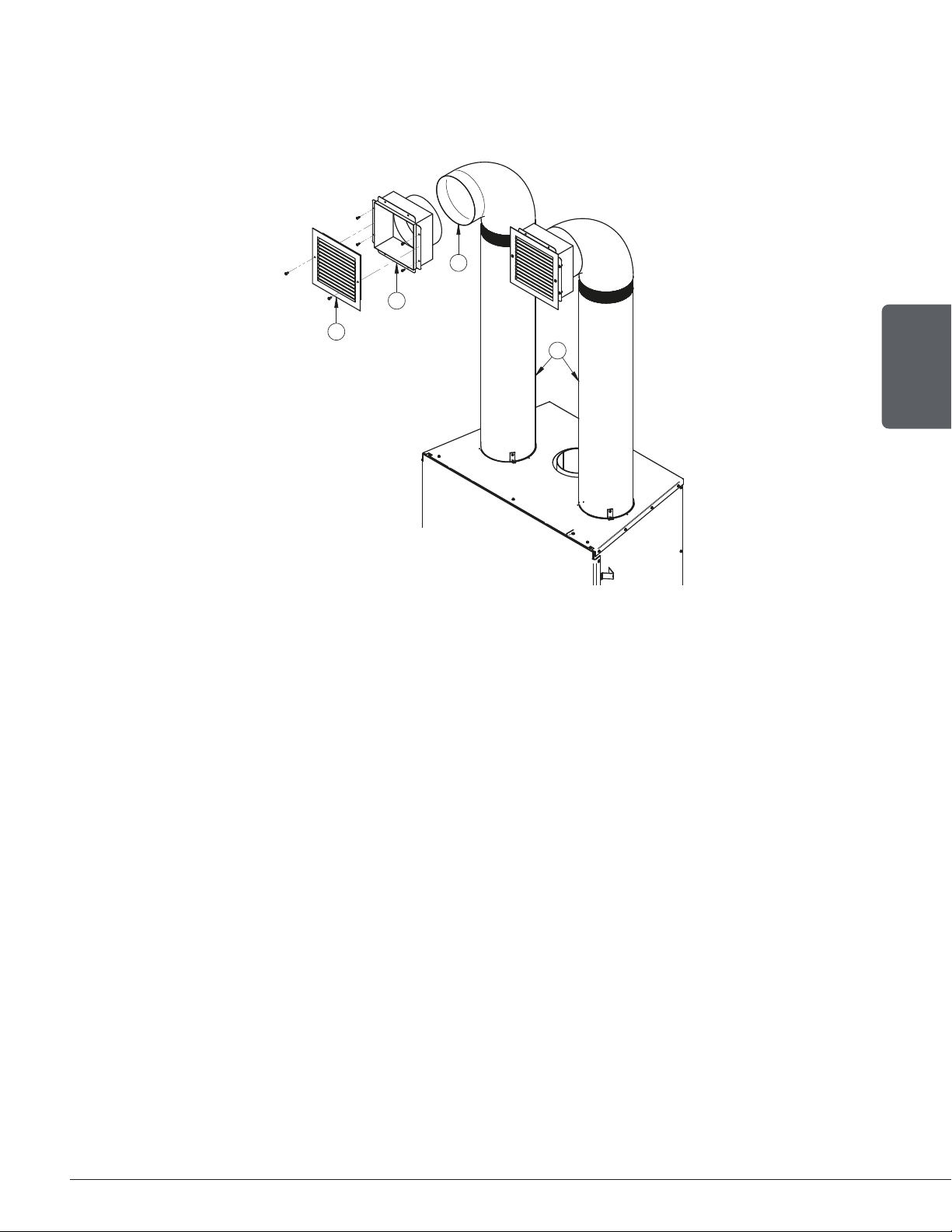
C) Fasten ducts (G) to 90 ° elbows (C) using self-drilling screws (3 per elbow). Insert the frames (B)
into the elbow outlets (C). Press the frame on the back of the non-combustible wall and screw
it in place. Screw the frame (B) to the outlet of the elbow (C) with 3 self-drilling screws in each.
Attach the decorative grilles (A) to the frames with screws.
C
B
A
G
ENGLISH
Installation and Operation Manual - HE275CF
Page 55
Page 56
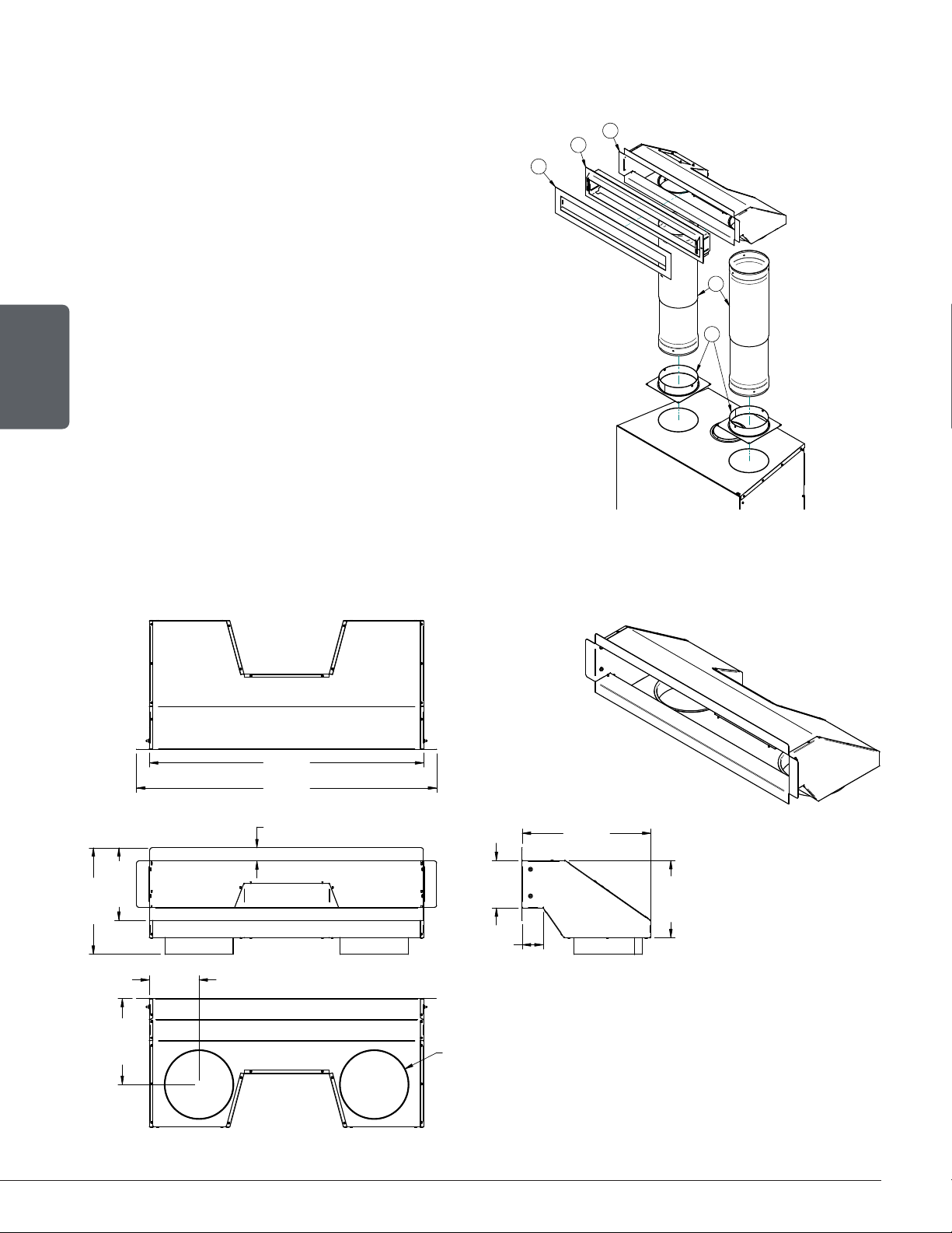
APPENDIX 3: OPTIONAL MODERN GRAVITY HOT AIR DISTRIBUTION KIT
INSTALLATION
The kit includes :
− Decorative plate (A);
− Adjustable frame (B);
− Heat distribution box (C);
− Telescoping section (D);
− Anchor plates (E);
− All screws are included.
Not included in the kit:
− 8" rigid ducting, 26 ga, galvanized steel.
(if necessary according to the desired height).
ENGLISH
Dimensions of heat distribution box
C
B
A
D
E
316mm
12 1/2"
Page 56
32 1/8"
816mm
35 1/8"
892mm
1 1/2"
TYP.
39mm
8 1/2"
215mm
5 3/4"
147mm
256mm
10 1/8"
O
2 1/2"
62mm
8"
203mm
5 1/2"
141mm
(2)
15 1/8"
383mm
9"
230mm
Installation and Operation Manual - HE275CF
Page 57
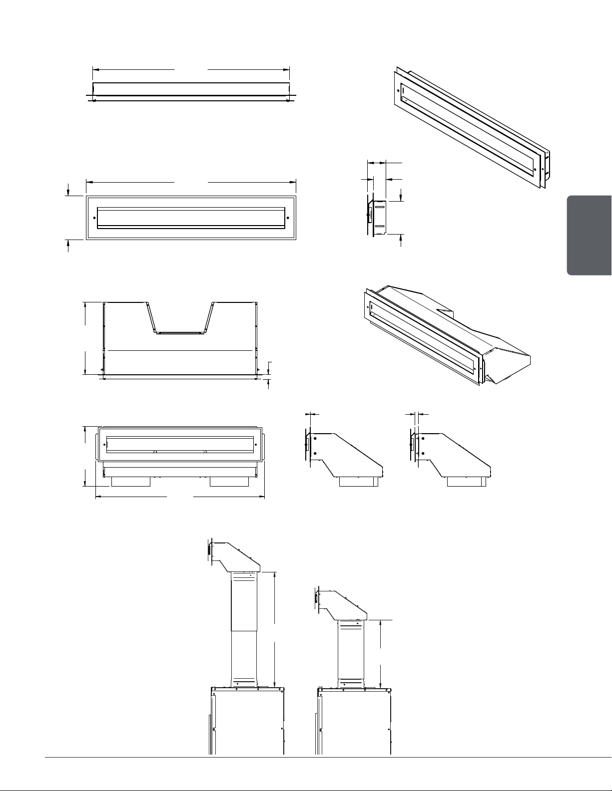
Dimensions of the decorative plate
32"
814mm
34 1/8"
867mm
3"
76mm
2"
52mm
7 1/8"
181mm
5 3/8"
138mm
Dimensions of assembled heat distribution box and adjustable decorative plate
384mm
15 1/8"
1"
25mm
0"
0mm
MIN.
316mm
12 1/2"
35 1/8"
892mm
11/16"
17mm
MAX.
ENGLISH
Dimensions of telescoping section
Installation and Operation Manual - HE275CF
36 1/8"
918mm
MAX
21 3/8"
543mm
MIN
Page 57
Page 58
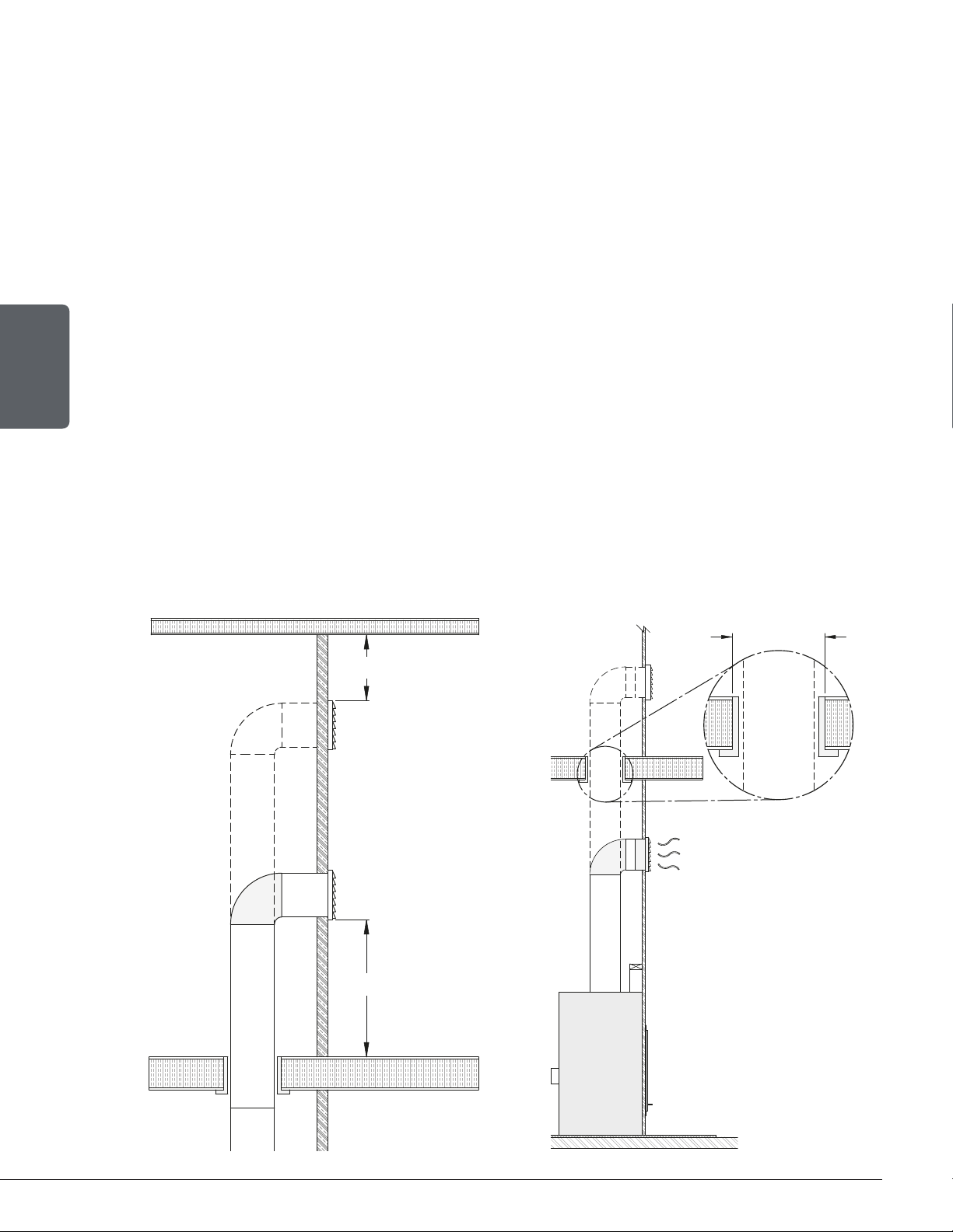
Installation rules and advice
• The minimum height of the hot air duct is 68“ (1.7 m). It must be measured from the base of the
fireplace to the top of the hot air outlets.
• Do not connect the hot air ducts to a central heating system. The malfunction of the heating system
would overheat the fireplace.
• Do not use insulated flexible ducts as they may overheat.
• Do not use «T» fittings or anything other than those listed below.
• The hot air outlets can be installed in the same room as the fireplace or it can be installed in a room
upstairs.
• When forced air kit is installed in conjunction with a gravity kit, the forced air device will draw some
of the air from the gravity kit ducting, therefore reducing its efficiency.
ENGLISH
Clearances
• There shall be a clearance of at least 12" (305 mm) between the hot air outlet frame and a ceiling,
side wall or mantle made of flammable material.
• When the duct passes through a wall or floor made of flammable material, a firestop radiation shield
(same as the one used for a class A chimney) must be installed in the opening of the wall or floor.
There must be a clearance of at least 2" (50 mm) between the ducts and the firestop.
12" MIN.
12" MIN.
13" X 13"
330mm X 330mm
Page 58
Installation and Operation Manual - HE275CF
Page 59
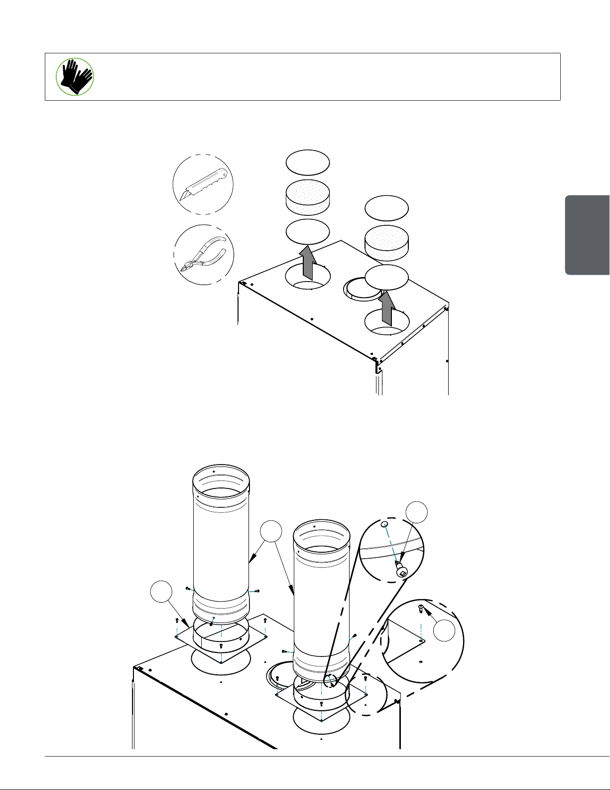
Installation
It is strongly recommended to wear gloves to complete the installation.
A) Remove the knockouts that close the 8" (20 cm) diameter holes on top of the fireplace. Then cut
and remove the insulation and the other set of knockouts inside the fireplace.
1
2
B) Secure the 2 anchor plates (E) with 8 screws provided (F) on top of the fireplace (4 for each
anchor plate). Insert the telescoping section (D) into each anchor plate and secure it with 6 other
self-tapping screws provided (G).
G
D
ENGLISH
E
Installation and Operation Manual - HE275CF
2
6X
F
1
8X
Page 59
Page 60
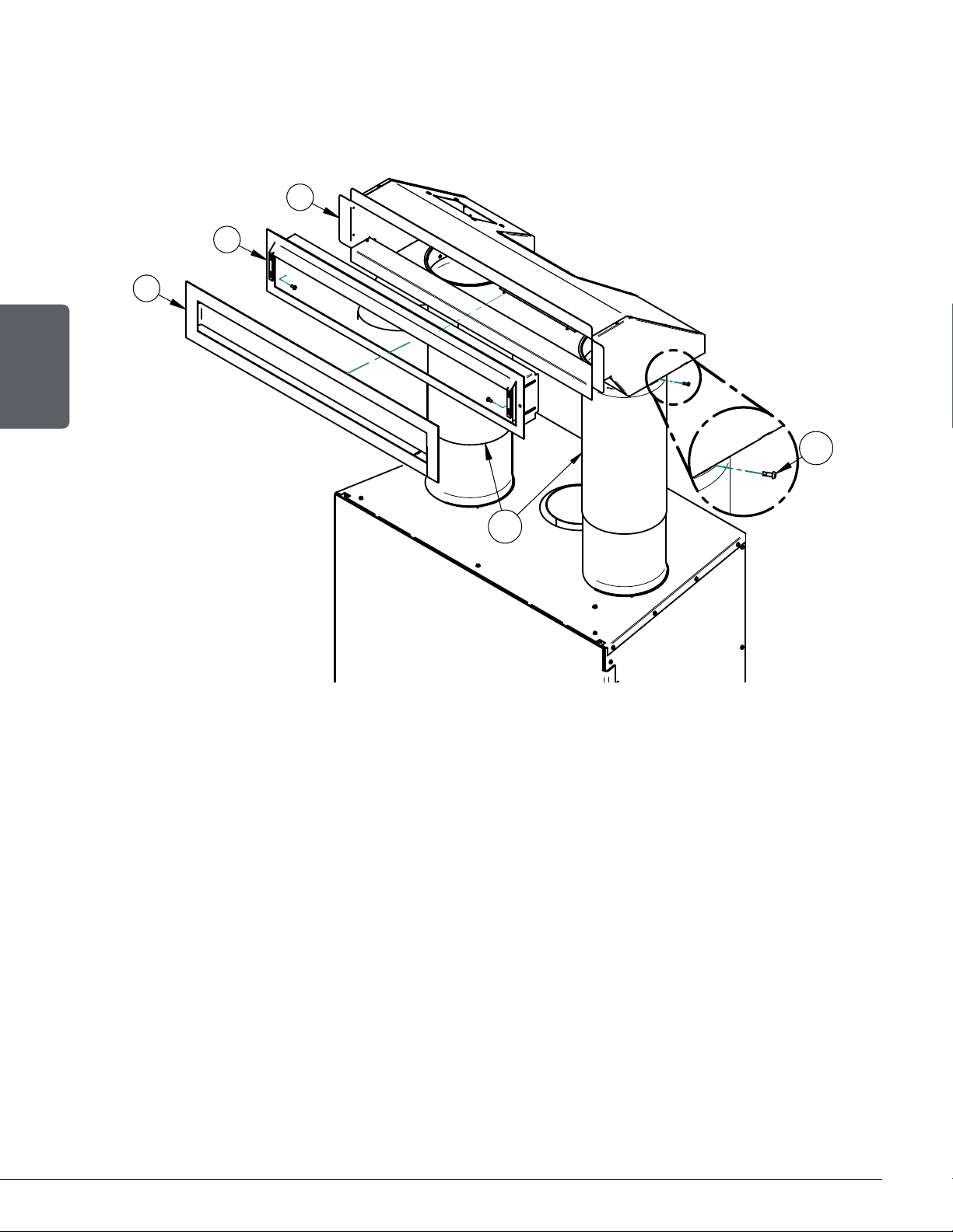
C) Secure the telescoping sections (D) to the heat distribution box (C) with self-tapping screws
(G) (3 per telescoping section). Determine the needed height and secure the two parts of the
telescoping sections together with 3 self-tapping screws. Insert the adjustable frame (B) in the
heat distribution box (C), press it against the non-combustible material and secure with 4 screws
into the heat distribution box. Set the decorative plate (A) to the adjustable frame (B).
C
B
A
ENGLISH
G
D
6X
Page 60
Installation and Operation Manual - HE275CF
Page 61
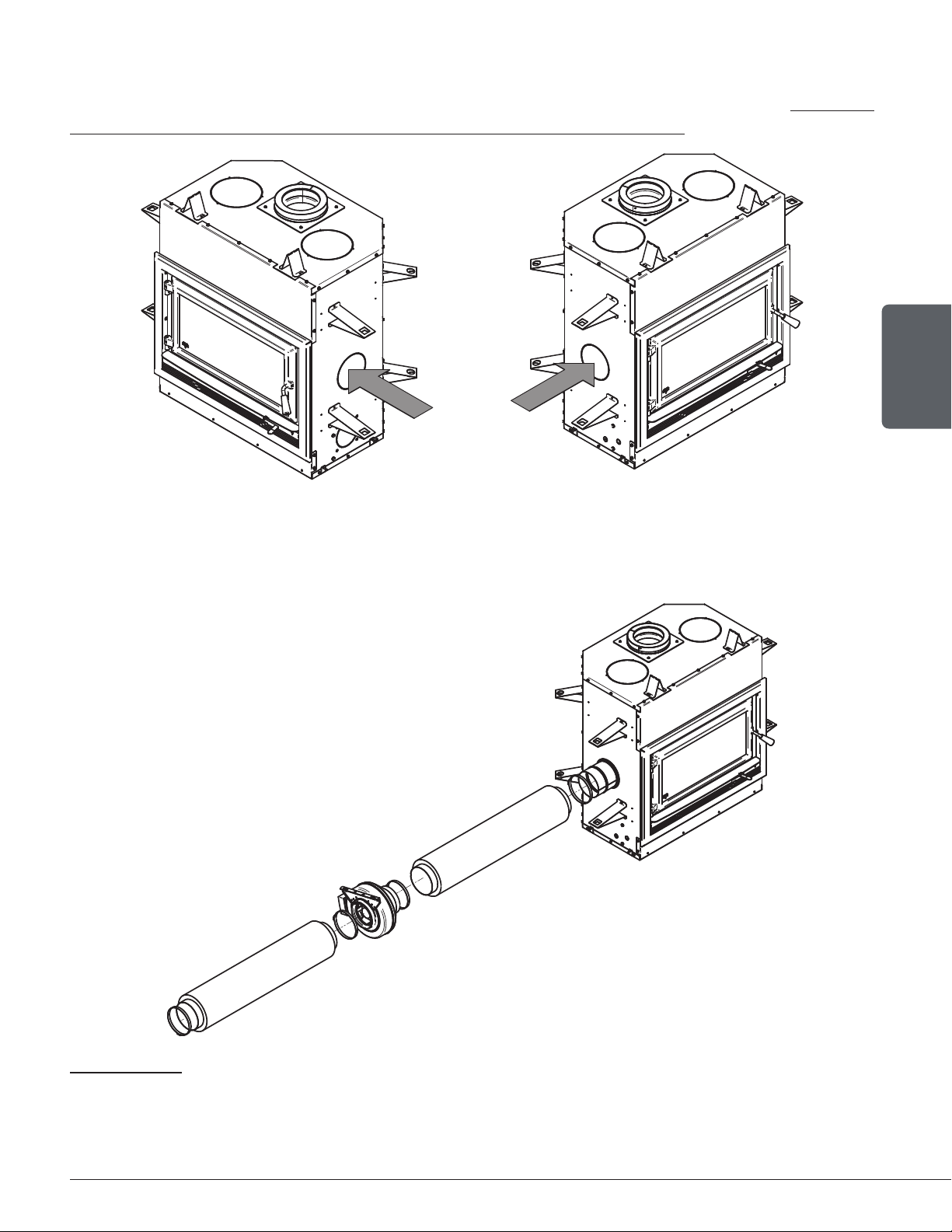
APPENDIX 4: OPTIONAL FORCED AIR DISTRIBUTION KIT INSTALLATION
It is possible to connect a forced air distribution kit18 on either sides of this fireplace. Installing
the kit on the left side of the fireplace will provide better performances than on the right side.
This kit allows distributing heat to another room up to 50 feet (15 m) of the fireplace. The
insulated flexible pipe (not included in the kit) must be HVAC type pipe and must comply with
ULC S110 and/or UL 181, Class 0 or Class 1 Standards and must withstand temperatures up to
250°F. For the complete installation procedure, see the installation manual provided with the kit.
ENGLISH
18
The EPA standard states that it is necessary to perform certication testing with any ventilation that is likely to alter the units’ performance. For this
reason, SBI has tested the effects of the forced air kit on the emissions of ne particles. Due to the design of the appliance and more specically to
the temperature sensor that is installed to control stops and starts, the forced ait kit does not affect the emission results. In fact, this option promotes
the recovery of excess heat to later redistribute it to other rooms. During testing, it was noted that the convection blowers underneath the rebox
had more of an effect on the ne particles emission due to the air being directed onto the rebox thus cooling the unit. However, this appliance has
already been tested for emission with one or more convection blowers. The environmental requirements are then met efciently.
Installation and Operation Manual - HE275CF
Page 61
Page 62
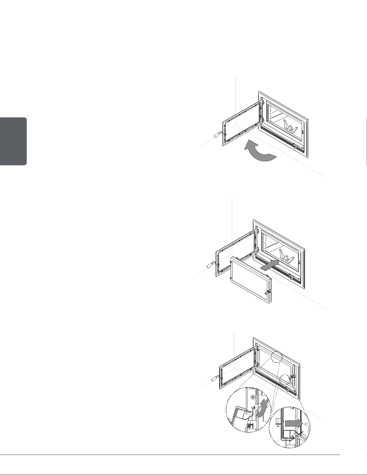
APPENDIX 5: OPTIONAL FIRE SCREEN INSTALLATION
A fire screen door can be installed on the fireplace. For more details, refer to the installation
manual supplied with the fire screen.
Warning: Never leave the fireplace unattended while in use with the firescreen.
1. Open the door.
ENGLISH
2. Hold the firescreen and bring it close to the
door opening.
3. Lean the upper part of the firescreen against
the top door opening making sure to insert
the top firescreen bracket behind the primary
air deflector.
4. Lift the firescreen upwards and push the
bottom part towards the fireplace then let
the firescreen rest on the bottom of the door
opening.
Page 62
Installation and Operation Manual - HE275CF
Page 63
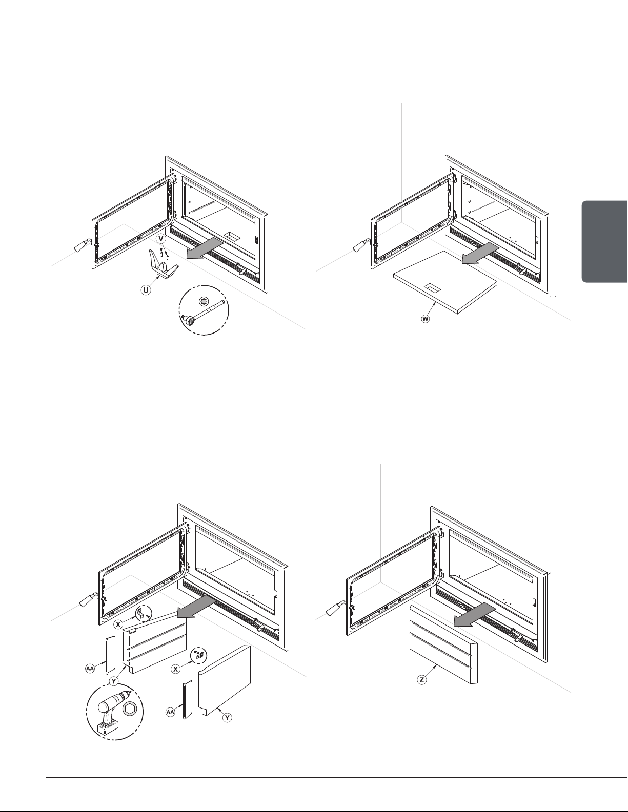
APPENDIX 6: REFRACTORY PANELS REPLACEMENT
1. Using a ratchet and a Torx (T-30) bit , unscrew
the two screws (V) holding the andiron (U).
2. Remove the floor refractory panel (W).
ENGLISH
3. Using a power driver, remove the refractory
panels brackets (X) and the side refractory
panels (Y), and front refractory protectors (AA).
4. Remove the back refractory panel (Z).
Installation and Operation Manual - HE275CF
Page 63
Page 64
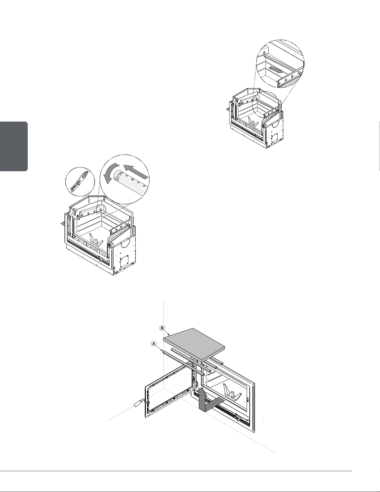
APPENDIX 7: SECONDARY AIR TUBES AND BAFFLE INSTALLATION
1. Starting with the rear tube, lean and insert
the right end of the secondary air tube into
the rear right channel hole. Then lift and
insert the left end of the tube into the rear
left channel.
2. Align the notch in the left end of the tube with
ENGLISH
the key of the left air channel hole. Using a
«Wise grip» hold the tube and lock it in place
by turning the tube as shown. Make sure the
notch reaches the end of the key way.
3. Repeat for center back tube.
4. Put the baffle in place.
5. Repeat steps 1 and 2 for the two front tubes.
6. To remove the tubes use the above steps in
reverse order.
Note that secondary air tubes (A) can be replaced without removing the baffle board (B).
Page 64
Installation and Operation Manual - HE275CF
Page 65
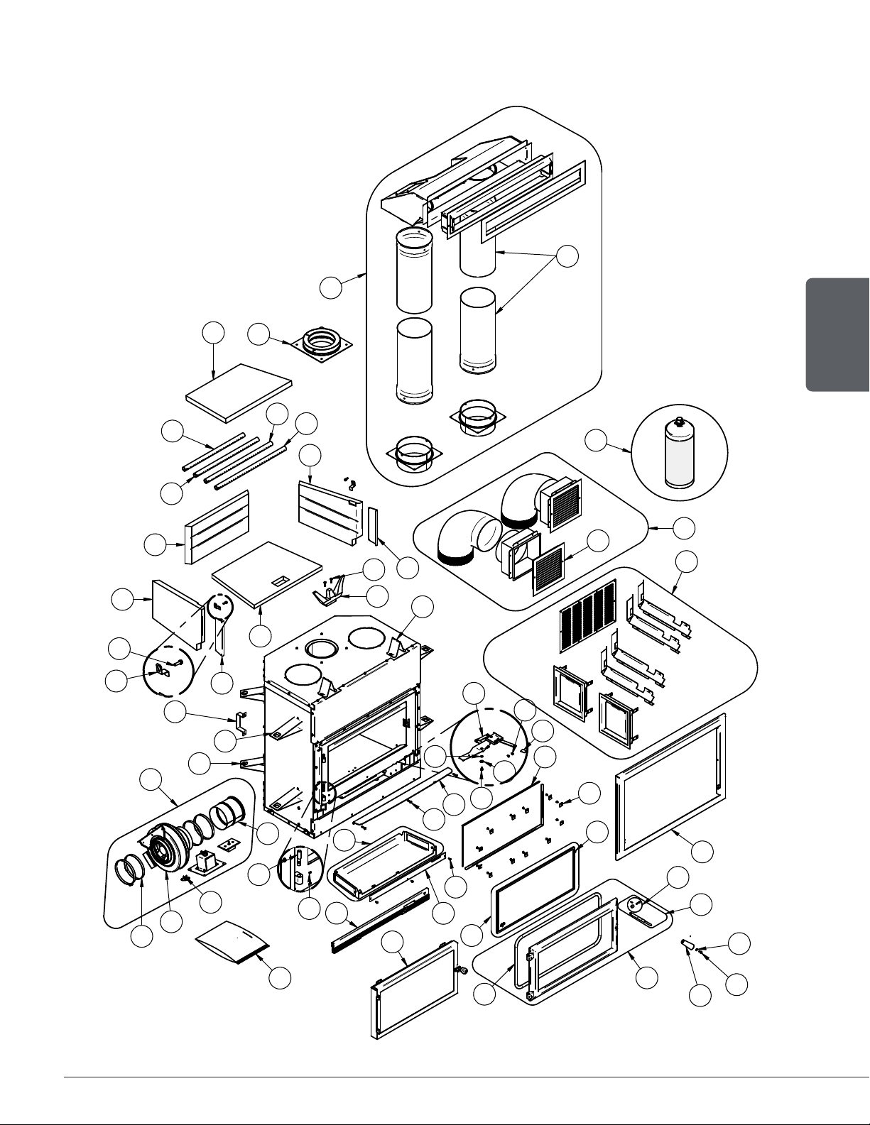
APPENDIX 8: EXPLODED DIAGRAM AND PARTS LIST
50
49
34
35
40
29
30
41
46
45
28
33
31
27
47
38
32
48
39
25
26
44
43
42
24
11
23
22
37
10
38
36
22
ENGLISH
51
52
18
17
16
3
20
21
13
12
9
15
19
14
8
53
54
55
7
6
3
56
Installation and Operation Manual - HE275CF
4
5
2
1
Page 65
Page 66

IMPORTANT: THIS IS DATED INFORMATION. When requesting service or replacement parts
for your unit, please provide the model number and the serial number. We reserve the right to
change parts due to technology upgrades or availability. Contact an authorized dealer to obtain
any of these parts. Never use substitute materials. Use of non-approved parts can result in poor
performance and safety hazards.
# Item Description Qty
1 30898 ROUND WOODEN BLACK HANDLE DULL BLACK FINISH 1
2 30025 1/4-20 X 1/2" PAN-HEAD QUADREX BLACK SCREW 1
3 30187 STAINLESS WASHER ID 17/64" X OD 1/2" 2
4 AC06500 SILICONE AND 5/8" X 8' BLACK DOOR GASKET KIT 1
5 SE24334 DOOR ASSEMBLY 1
6 SE72135 REPLACEMENT HANDLE WITH LATCH KIT 1
7 AC09185 DOOR LATCH KIT 1
ENGLISH
8 AC06400 3/4" (FLAT) X 6' BLACK SELF-ADHESIVE GLASS GASKET 1
9 SE72341 VENTIS GLASS 1
10 AC01275 FIRESCREEN DOOR 1
11 SE72381 BOTTOM CAGE ASSEMBLY 1
12 PL72188 AIR INTAKE CLOSING PLATE 1
13 30154 BLACK SCREW #10 X 5/8" QUADREX #2 TYPE A 3
14 SE53585 GLASS RETAINER KIT WITH SCREWS (12 PER KIT) 1
15 PL72314 GLASS FRAME 2
16 30556 AIR CONTROL FINISHING TIP 1
17 30029 THREAD CUTTING SCREW 10-24 TYPE "F" X 3/8" HEX WASHER 2
18 SE72269 AIR CONTROL DAMPER ASSEMBLY 1
19 30206 ZINC WASHER 5/16"ID X 3/4"OD 1
20 30060 THREAD-CUTTING SCREW 1/4-20 X 1/2" F HEX STEEL SLOT WASHER C102 ZINC 1
21 PL72141 DECORATIVE ASH SHELF 1
22 30506 SCREW PAN TORX TYPE F 1/4-20 X 1" BLACK 5
23 SE72187 AIR TIGHT CHANNEL ASSEMBLY 1
24 30117 SOCKET SET SCREW #10-32 X 1/4" 2
25 30586 HINGE PIN 2
26 PL69151 ADAPTER 6" 1
27 44028 CERAMIC THERMODISC F110-20F 1
28 44142 BLOWER 6'' 300 CFM 1
29 49608 All stainlesss steel clamp 114 to 165 mm 4
30 AC01363 FORCED AIR KIT 1
31 PL72246 REAR SIDE SPACER 4
32 PL72245 SIDE SPACER 4
33 PL53065 REAR STANDOFF 2
34 PL72040 REFRACTORY PANEL BRACKET 2
35 30094 HEX SCREW WASHER HEAD 1/4-20 X 3/4" F ZINC TYPE 2
Page 66
Installation and Operation Manual - HE275CF
Page 67
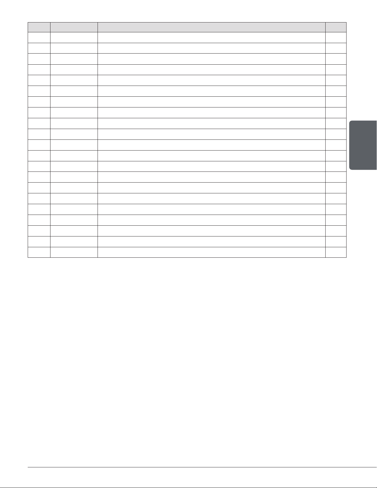
# Item Description Qty
36 PL72177 TOP STANDOFF 2
37 PL53144 ANDIRON 1
38 PL66568 FRONT REFRACTORY PROTECTOR 2
39 22141 FLOOR REFRACTORY SLAB 1
40 22152 LEFT REFRACTORY 1
41 22150 REAR REFRACTORY 1
42 22151 REFRACTORY RIGHT STONE 1
43 PL72049 FRONT SECONDARY AIR TUBE 1
44 PL72048 CENTER FRONT SECONDARY AIR TUBE 1
45 PL72047 CENTER BACK SECONDARY AIR TUBE 1
46 PL72046 BACK SECONDARY AIR TUBE 1
47 21578 C-CAST BAFFLE 1
48 CVA-AP06 6" STAINLESS STEEL ANCHOR PLATE 1
49 AC01389 HOT AIR GRAVITY KIT - MODERN WITH ADJUSTABLE PIPES 1
50 SE66646 GRAVITY PIPE EXTENTION KIT UNPAINTED 1
51 AC05959 METALLIC BLACK STOVE PAINT - 342 g (12oz) AEROSOL 1
52 30540 HOT AIR GRAVITY DISTRIBUTION KIT GRILL 2
53 AC01375 HOT AIR GRAVITY KIT - TRADITIONAL 1
54 AC01224 CHASE REDUCTION KIT 1
55 SE72380 FACADE HE275CF ASSEMBLY 1
56 SE46181 INSTRUCTION MANUAL KIT VB00017 (HE275CF) 1
ENGLISH
Installation and Operation Manual - HE275CF
Page 67
Page 68

VENTIS LIMITED LIFETIME WARRANTY
The warranty of the manufacturer extends only to the original retail purchaser and is not transferable. This warranty
covers brand new products only, which have not been altered, modied nor repaired since shipment from the factory.
Proof of purchase (dated bill of sale), model name and serial number must be supplied when making any warranty
claim to the VENTIS dealer.
This warranty applies to normal residential use only. This warranty is void if the unit is used to burn material other
than cordwood (for which the unit is not certied by EPA) and
Damages caused by misuse, abuse, improper installation, lack of maintenance, over ring, negligence or accident
during transportation, power failures, downdrafts, venting problems or underestimated heating area are not covered
by this warranty. The recommended heated area for a given appliance is dened by the manufacturer as its capacity
to maintain a minimum acceptable temperature in the designated area in case of a power failure.
This warranty does not cover any scratch, corrosion, distortion, or discoloration. Any defect or damage caused by
the use of unauthorized or o
perform the installation in accordance with the instructions supplied with this product and all local and national
building codes. Any service call related to an improper installation is not covered by this warranty.
The manufacturer may require that defective products be returned or that digital pictures be provided to support the
claim. Returned products are to be shipped prepaid to the manufacturer for investigation. Transportation fees to ship
the product back to the purchaser will be paid by the manufacturer. Repair work covered by the warranty,
at the purchaser’s domicile by an authorized qualied technician requires the prior approval of the manufacturer. All
parts and labour costs covered by this warranty are limited according to the table below.
The manufacturer, at its discretion, may decide to repair or replace any part or unit after inspection and investigation
of the defect. The manufacturer may, at its discretion, fully discharge all obligations with respect to this warranty
by refunding the wholesale price of any warranted but defective parts. The manufacturer shall, in no event, be
responsible for any uncommon, indirect, consequential damages of any natur
purchase price of the product. A one-time replacement limit applies to all parts beneting from lifetime coverage. This
warranty applies to products purchased after March 1st 2019.
ther than the original parts voids this warranty. An authorized qualied technician must
void if not operated according to the owner's manual.
executed
e, which are in excess of the original
WARRANTY
DESCRIPTION
Combustion chamber (welds only) and cast iron door frame. Lifetime 3 years
Surrounds, heat shields, ash drawer, steel legs, pedestal, trims (aluminum extrusions),
plating (defective manufacture**), and convector air-mate.
Removable stainless steel combustion chamber components, secondary air tubes**,
deectors, and supports.
Glass retainers, handle assembly, and air control mechanism. 5 years 3 years
Carbon steel combustion chamber components, vermiculite bafe**, and C-Cast bafe**. 5 years N/A
Standard blower, heat sensors, switches, rheostat, wiring, and other controls. 2 years 1 year
Optional blower, paint (peeling**), ceramic glass (thermal breakage only**), ceramic bre
blankets, gaskets, insulation, and other options.
Firebricks. N/A N/A
All parts replaced under the warranty. 90 days N/A
*Subject to li mitations above. **Picture required.
Labour cost and repair work to the account of the manufacturer are based on a predetermined rate schedule and
must not exceed the wholesale price of the replacement parts. Shall your unit or a component be defective, contact
immediately your VENTIS dealer. To accelerate processing of your warranty claim, make sure to have on hand the
following information when calling:
• Your name, address and telephone number;
• Bill of sale and dealer’s name;
• Installation conguration;
• Serial number and model name as indicated on the
nameplate xed to the back of your unit;
• Nature of the defect and any relevant information.
APPLICATION*
PARTS LABOUR
Lifetime S.O.
7 years N/A
1 year N/A
Before shipping your unit or defective component to our plant, you must obtain an Authorization
Number from your VENTIS dealer. Any merchandise shipped to our plant without authorization will be
refused automatically and returned to the sender.
Page 69

Page 70

This document is available for free download on the
manufacturer’s website. It is a copyrighted document.
Resale is strictly prohibited. The manufacturer may update
this document from time to time and cannot be responsible
for problems, injuries, or damages arising out of the use
of information contained in any document obtained from
unauthorized sources.
Stove Builder International inc.
250, De Copenhague street,
St-Augustin-de-Desmaures (Québec), Canada
G3A 2H3
418-908-8002
https://www.valcourtinc.com/en/
 Loading...