

VentilClima VCE20, VCE10, VCE30, VCE40, VCE60 Technical Manual
...
TECHNICAL MANUAL
>>
CENTRIFUGAL FAN COIL UNITS
MU VCE 0107-1 VEN GB

ISO 9001:2000 - Cert. n. 1368/1
TECHNICAL DATAS
General dimensions of 2 pipes system fancoil - VCE1x-6x 3
General dimensions of 4 pipes system fancoil - VCE1x-6x 3
General dimensions of 2 pipes system fancoil - VCE7x-12x 4-5
General dimensions of 4 pipes system fancoil - VCE7x-12x 4-5
General datas of 2 pipes system fancoil - VCE 1x-6x 6
Correction coefficients for different available speeds - 2 pipes system 6
General datas of 2 pipes system fancoil - VCE7x-12x 7
Correction coefficients for different available speeds - 2 pipes system 7
General datas of 4 pipes system fancoil - VCE 1x-6x 8
Correction coefficients for different available speeds - 4 pipes system 8
TECHNICAL MANUAL
General datas of 4 pipes system fancoil - VCE7x-12x 9
Correction coefficients for different available speeds - 4 pipes system 9
Working limits 10
Aeraulic performance
Mod. VCE10 - 2 pipes system 11
Mod. VCE20 - 2 pipes system 11
Mod. VCE30 - 2 pipes system 11
Mod. VCE40 - 2 pipes system 11
Mod. VCE50 - 2 pipes system 12
Mod. VCE60 - 2 pipes system 12
Mod. VCE70 - 2 pipes system 12
Mod. VCE80 - 2 pipes system 12
Mod. VCE90 - 2 pipes system 13
Mod. VCE100 - 2 pipes system 13
Mod. VCE110 - 2 pipes system 13
Mod. VCE120 - 2 pipes system 13
Mod. VCE10 - 4 pipes system 14
Mod. VCE20 - 4 pipes system 14
Mod. VCE30 - 4 pipes system 14
Mod. VCE40 - 4 pipes system 14
Mod. VCE50 - 4 pipes system 14
Mod. VCE60 - 4 pipes system 15
Mod. VCE70 - 4 pipes system 15
Mod. VCE80 - 4 pipes system 15
Mod. VCE90 - 4 pipes system 15
Mod. VCE100 - 4 pipes system 15
Mod. VCE110 - 4 pipes system 16
Mod. VCE120 - 4 pipes system 16
Fancoil sound power spectrum, 2 pipe system - 1x-12x 17
Fancoil sound power spectrum, 4 pipe system - 1x-12x 18
Vertical recessed fancoil unit model
Version VCE12-VCE122: top air discharge 29
Version VCE17-VCE127: frontal air discharge 30
Horizontal recessed fancoil unit model
Version VCE13-VCE123: frontal air discharge 31
FAN COIL UNITS ACCESSORIES
2 way valve kit 32
3 way valve kit 33
Auxiliary 1 row coil 34
Electric heater 34
Auxiliary condensate drain pan - vertical version 34
Auxiliary condensate drain pan - horizontal version 35
Condensate drain pump 35
Fresh air louver
for VCEx0 versions 35
for VCEx8 versions 36
for VCEx1 versions 36
for VCEx2 e VCEx7 versions 36
for VCEx3 versions 36
Pair of enamelled feet 37
Outlet union with circular fittings 38
Inlet union with air filter circular fittings 38
Straight outlet fitting 38
90° outlet elbow 38
Intake elbow 38
Telescopic extention for straight fittings and elbows 38
Anti-vibration joint 38
Outlet louvres and intake grille (with air filter) 39
Aluminium adjustable supply air grill without filter 39
Aluminium fix intake air grill with air filter 39
Example of use of fitting and grilles/louvres 40
Special steel box (only VCEx7) 40
Pre-enamelled white sheet metal panel (VCEx7 version) 41
Pre-enamelled white sheet metal panel (VCEx2 and VCEx3 version) 41
White lacquared wood panel (VCEx7 version) 42
White lacquared wood panel (VCEx2 and VCEx3 version) 42
Air pressure drops for the main accessories - VCE1x-9x 19-20
Water coils pressure drop diagram - 1x-12x 21
FANCOIL UNIT DIMENSION
General features and main components 22
Wall vertical version with cabinet:
Version VCE10-VCE120: bottom air intake 23
Version VCE18-VCE128: frontal air intake with socle 24
Version VCE15-VCE95: frontal air intake 25
Ceiling horizontal version with cabinet
Version VCE14-VCE94: bottom air intake 26
Version VCE11-VCE121: bottom air intake with socle 27
Version VCE19-VCE129: rear air intake 28
range
Pre-enamelled rear panel (for standard cabinet) 43
Pre-enamelled rear panel (for cabinet with socle) 43
Bottom panel without grille 43
Bottom panel with grille and air filter 43
CONTROL PANEL ON BOARD
Base control panel on board without thermostat 44
Control panel on board with electromechanical thermostat 45-46
Control panel on board with electronical thermostat 46-47
REMOTE CONTROL
Remote control CD1 48
Temperature controller CD8 48
Interface chart for the control of 4 fan coil mod. SDI 49
2
122 233
34
25
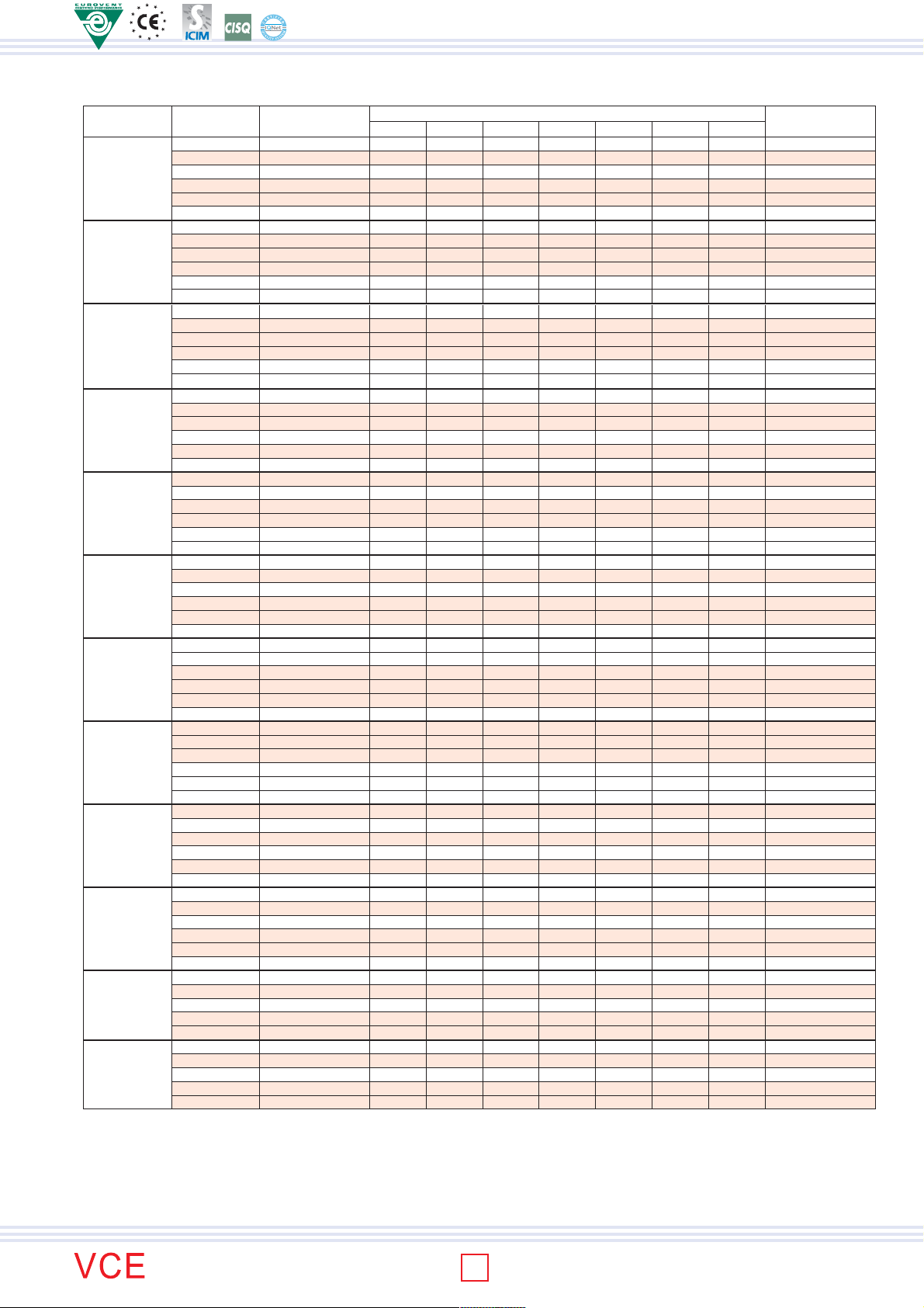
Lenght with cabinet [ L ]
Lenght without cabinet [ M ]
25
103 53
109
39
337 67
274 137
Height with cabinet 480
Height without cabinet 460
147
Ø20
200
179
12
12
108
Depth without cabinet 220
Depth with cabinet 225
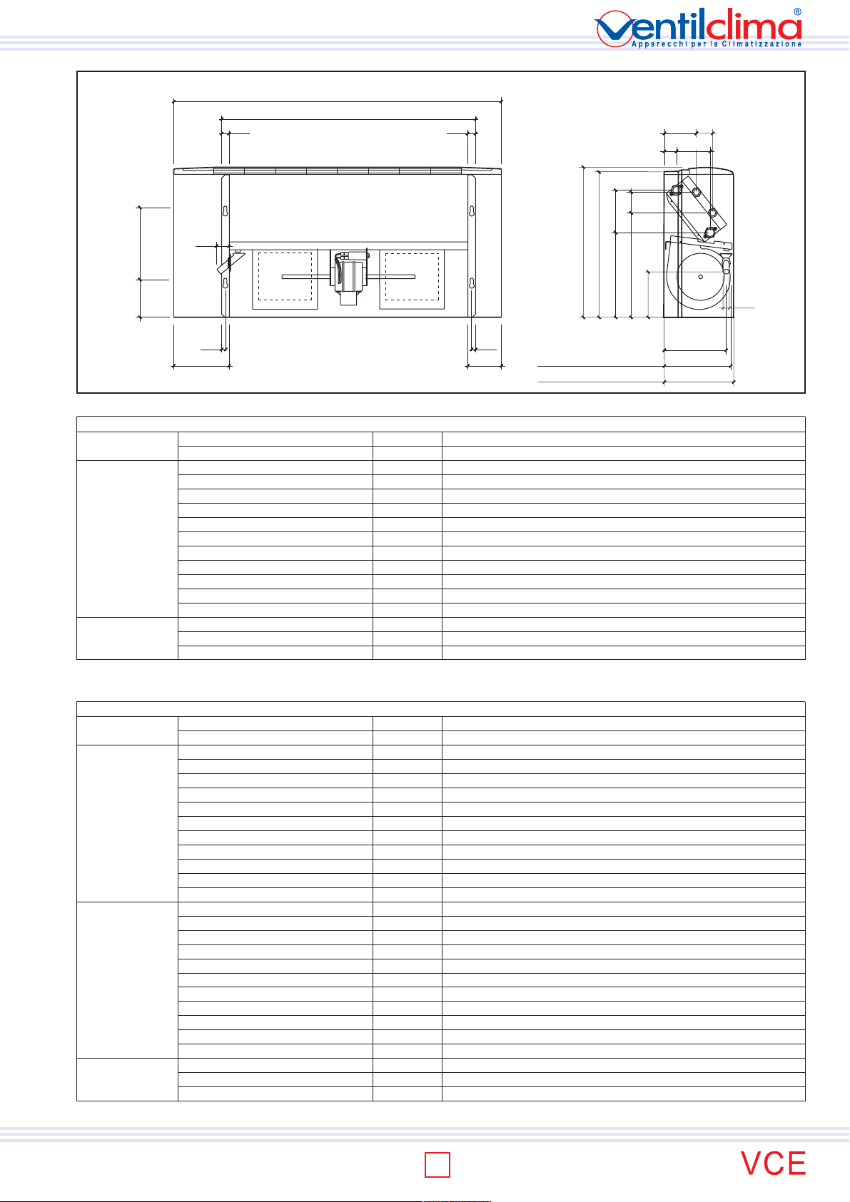
FAN-COIL GENERAL DIMENTIONS FOR 2 PIPE SYSTEM (VCE10-60)
MODEL VCE10 VCE20 VCE30 VCE40 VCE50 VCE60
Coil used for both
cooling and heating
General features
Fans number n° 1 1 2 2 2 2
Coils number n° 1 1 1 1 1 1
Rows number n° 3 3 3 3 3 3
Finned pack length mm 290 490 690 690 890 890
Number of pipes for row n° 8 8 8 8 8 8
Fin spacing mm 2,1 2,1 2,5 2,1 2,5 2,1
Number of feeding circuits n° 3 3 3 3 3 3
Shape mm x mm 25 x 22 25 x 22 25 x 22 25 x 22 25 x 22 25 x 22
Finned pack depth mm 66 66 66 66 66 66
Frontal surface m2 0,058 0,098 0,138 0,138 0,178 0,178
Fins total surface m2 3,278 5,538 6,635 7,798 8,558 10,059
Water content litri 0,59 0,93 1,27 1,27 1,61 1,61
Hydraulic connections (Ø female gas) Ø 3/4" 3/4" 3/4" 3/4" 3/4" 3/4"
Lenght with cabinet L (mm) 660 860 1060 1060 1260 1260
Lenght without cabinet M (mm) 420 620 820 820 1020 1020
Net weight kg 14 17 22 23 27 28
FAN-COIL GENERAL DIMENTIONS FOR 4 PIPE SYSTEM (VCE10-60)
MODELLO VCE10 VCE20 VCE30 VCE40 VCE50 VCE60
Fans number n° 1 1 2 2 2 2
Coils number n° 2 2 2 2 2 2
Rows number n° 3 3 3 3 3 3
Finned pack length mm 290 490 690 690 890 890
Number of pipes for row n° 8 8 8 8 8 8
Fin spacing mm 2,1 2,1 2,5 2,1 2,5 2,1
Cooling coil
Heating coil
General features
Number of feeding circuits n° 3 3 3 3 3 3
Shape mm x mm 25 x 22 25 x 22 25 x 22 25 x 22 25 x 22 25 x 22
Finned pack depth mm 66 66 66 66 66 66
Frontal surface m2 0,058 0,098 0,138 0,138 0,178 0,178
Fins total surface m2 3,278 5,538 6,635 7,798 8,558 10,059
Water content litri 0,59 0,93 1,27 1,27 1,61 1,61
Hydraulic connections (Ø female gas) Ø 3/4" 3/4" 3/4" 3/4" 3/4" 3/4"
Rows number n° 1 1 1 1 1 1
Finned pack length mm 280 480 680 680 880 880
Number of pipes for row n° 8 8 8 8 8 8
Fin spacing mm 2,1 2,1 2,5 2,1 2,5 2,1
Number of feeding circuits n° 1 1 1 1 1 1
Shape mm x mm 25 x 25 25 x 25 25 x 25 25 x 25 25 x 25 25 x 25
Finned pack depth mm 25 25 25 25 25 25
Frontal surface m2 0,056 0,096 0,136 0,136 0,176 0,176
Fins total surface m2 1,233 2,115 2,544 2,996 3,292 3,877
Water content litri 0,19 0,31 0,42 0,42 0,53 0,53
Hydraulic connections (Ø female gas) Ø 1/2" 1/2" 1/2" 1/2" 1/2" 1/2"
Lenght with cabinet L (mm) 660 860 1060 1060 1260 1260
Lenght without cabinet M (mm) 420 620 820 820 1020 1020
Net weight kg 15 18 23 24 28 29
TECHNICAL MANUAL
range
3
ISO 9001:2000 - Cert. n. 1368/1
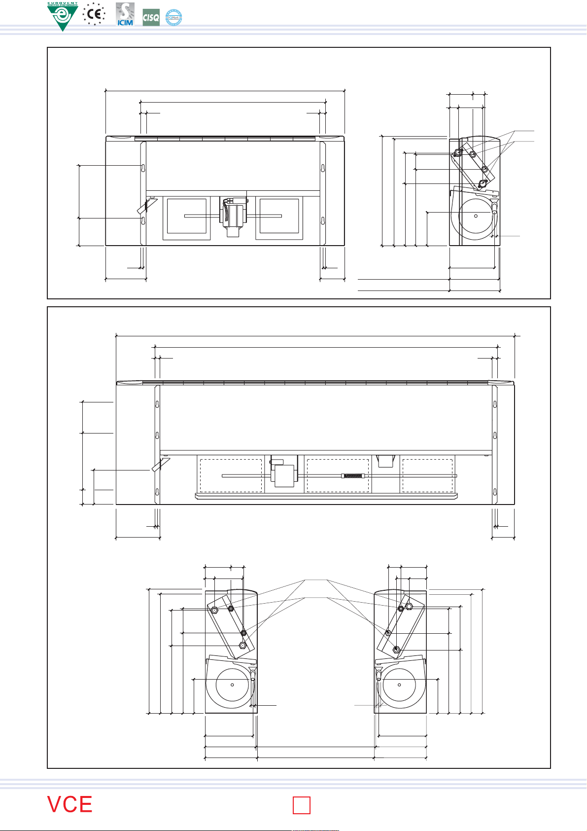
MODEL VCE 70, 80, 90
25 25
TECHNICAL MANUAL
122 253
12
173
25 25
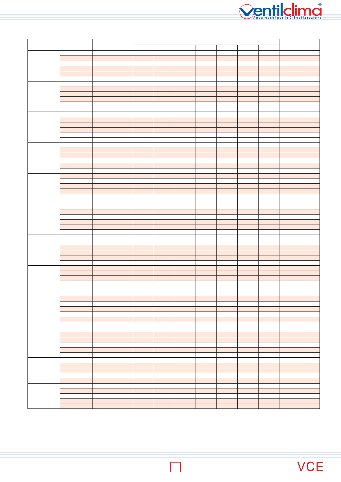
Lenght with cabinet [ L ]
Lenght without cabinet [ M ]
MODEL VCE 100, 110, 120
Lenght with cabinet [ L ]
Lenght without cabinet [ M ]
12
108
41
253
374 124
286
Height with cabinet 585
Height without cabinet 580
Depth without cabinet 220
Depth with cabinet 225
147
101
52
107
3/4" G
1/2" G
Ø 20
200
153
278
72
167
12
216
LEFT VERSION RIGHT VERSION
173
395 120
333
Height with cabinet 602
Height without cabinet 585
167
39
115
141
62
Ø20
3/4" G
1/2" G
Ø20
62
62
113
76
167
12
116
215
389 120
308
Height with cabinet 602
Height without cabinet 585
range
234 234
Depth without cabinet 252
Depth with cabinet 257
4
FAN-COIL GENERAL DIMENTIONS FOR 2 PIPE SYSTEM (VCE 70-120)
MODEL VCE70 VCE80 VCE90 VCE100 VCE110 VCE120
Fans number n° 2 2 2 3 3 3
Coils number n° 1 1 1 1 1 1
Rows number n° 3 3 3 3 3 3
Finned pack length mm 890 1.090 1.090 1.225 1.525 1.525
Number of pipes for row n° 12 12 12 12 12 12
Fin spacing mm 2,5 2,1 2,1 2,1 2,5 2,1
Coil used for both
cooling and heating
General features
Number of feeding circuits n° 3 6 6 6 8 8
Shape mm x mm 25 x 22 25 x 22 25 x 22 25 x 22 25 x 22 25 x 22
Finned pack depth mm 66 66 66 66 66 66
Frontal surface m2 0,267 0,327 0,327 0,368 0,458 0,458
Fins total surface m2 15,088 18,479 18,479 20,767 21,996 25,853
Water content litri 2,42 2,93 2,93 3,28 4,04 4,04
Hydraulic connections (Ø female gas) Ø 3/4" 3/4" 3/4" 3/4" 3/4" 3/4"
Lenght with cabinet L (mm) 1.260 1.460 1.460 1.660 1.960 1.960
Lenght without cabinet M (mm) 1.020 1.220 1.220 1.380 1.680 1.680
Net weight kg 30 35 36 46 55 57
FAN-COIL GENERAL DIMENTIONS FOR 4 PIPE SYSTEM (VCE70 - 120)
MODEL VCE70 VCE80 VCE90 VCE100 VCE110 VCE120
Fans number n° 2 2 2 3 3 3
Coils number n° 2 2 2 2 2 2
Rows number n° 3 3 3 3 3 3
Finned pack length mm 890 1.090 1.090 1.225 1.525 1.525
Number of pipes for row n° 12 12 12 12 12 12
Fin spacing mm 2,1 2,5 2,1 2,1 2,5 2,1
Cooling coil
Heating coil
General features
Number of feeding circuits n° 3 6 6 6 8 8
Shape mm x mm 25 x 22 25 x 22 25 x 22 25 x 22 25 x 22 25 x 22
Finned pack depth mm 66 66 66 66 66 66
Frontal surface m2 0,267 0,327 0,327 0,368 0,458 0,458
Fins total surface m2 15,088 18,479 18,479 20,767 21,996 25,853
Water content litri 2,42 2,93 2,93 3,28 4,04 4,04
Hydraulic connections (Ø female gas) Ø 3/4" 3/4" 3/4" 3/4" 3/4" 3/4"
Rows number n° 1 1 1 1 1 1
Finned pack length mm 880 1.080 1.080 1.225 1.525 1.525
Number of pipes for row n° 12 12 12 12 12 12
Fin spacing mm 2,1 2,5 2,1 2,1 2,5 2,1
Number of feeding circuits n° 1 1 1 2 3 3
Shape mm x mm 25 x 25 25 x 25 25 x 25 25 x 25 25 x 25 25 x 25
Finned pack depth mm 25 25 25 25 25 25
Frontal surface m2 0,176 0,216 0,216 0,368 0,458 0,458
Fins total surface m2 3,877 9,515 9,515 8,095 8,558 10,077
Water content litri 0,53 1,29 1,29 1,09 1,35 1,35
Hydraulic connections (Ø female gas) Ø 1/2" 1/2" 1/2" 1/2" 1/2" 1/2"
Lenght with cabinet L (mm) 1.260 1.460 1.460 1.660 1.960 1.960
Lenght without cabinet M (mm) 1.020 1.220 1.220 1.380 1.680 1.680
Net weight kg 32 38 39 49 58 60
TECHNICAL MANUAL
range
5
ISO 9001:2000 - Cert. n. 1368/1
TECHNICAL DATA
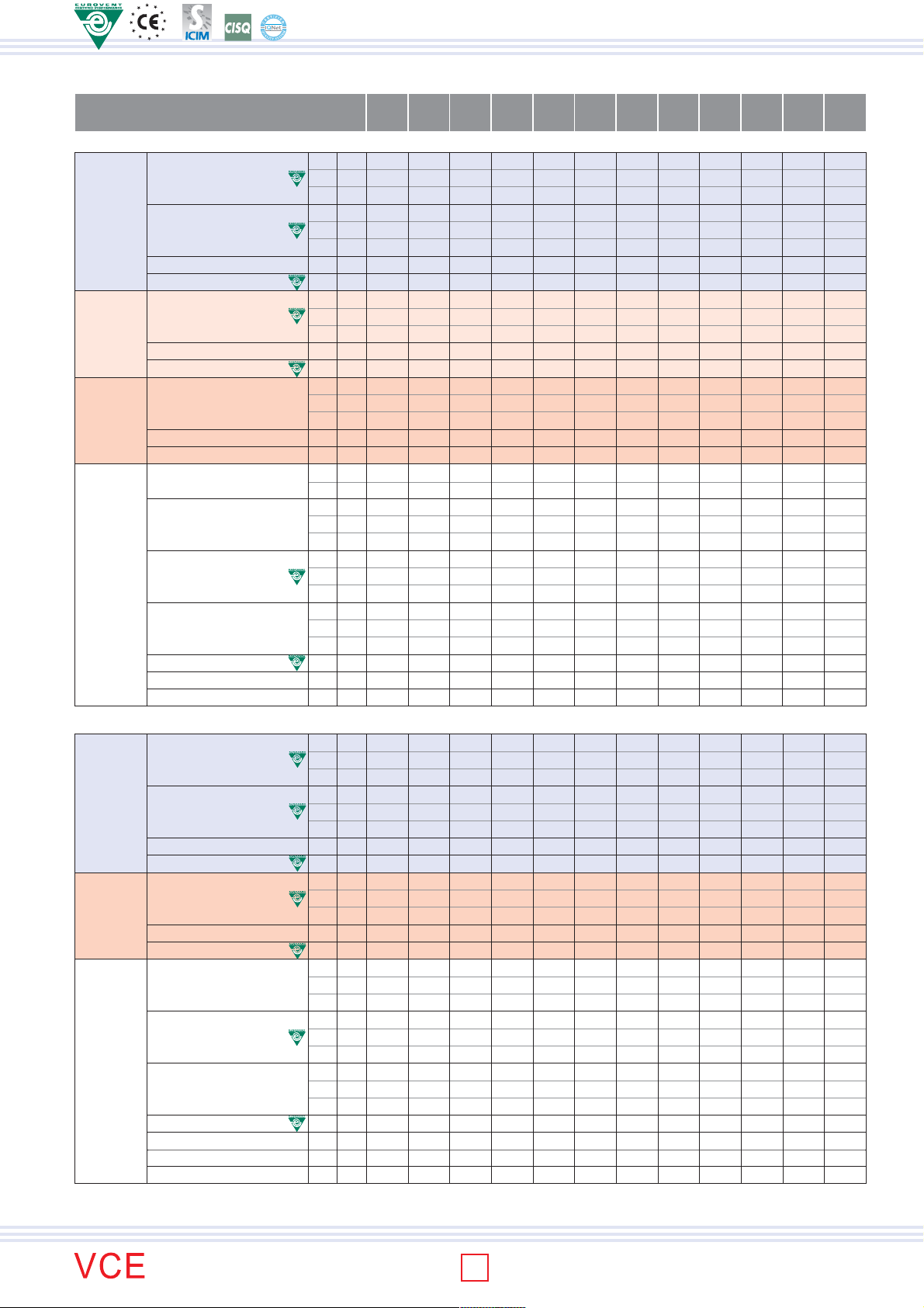
MODEL 10 20 30 40 50 60 70 80 90 100 110 120
SPEEDS SET IN THE FACTORY 2° 4° 5° 2° 3° 4° 2° 3° 4° 2° 3° 5° 1° 3° 4° 2° 4° 5° 3° 4° 5° 1° 2° 3° 1° 3° 5° 2° 3° 5° 2° 3° 5° 2° 4° 5°
2 pipe system (3R coil)
Total cooling capacity
COOLING
Sensible cooling capacity
27°C d.b.-19°C w.b.
Inlet air temperature:
Water flow
Inlet water temperature: 7 °C
Outlet water temperature: 12°C
Water pressure loss
Heating capacity
: 50°C
TECHNICAL MANUAL
Inlet water
HEATING
HEATING
Water flow
temperature
Air temperature: 20°C
Water pressure loss
Heating capacity
: 70/60°C
Inlet water
Water flow
Air temperature: 20°C
temperature
Water pressure loss
Electric heater capacity
Air flow
Sound power level
FURTHER DATA
Sound pressure level
Power input
Absorbet current
Water content
W max 860 1.280 2.170 2.530 3.110 3.850 4.330 5.590 6.900 7.970 10.010 11.010
W med 790 1.170 1.940 2.030 2.790 3.410 3.710 5.170 5.960 6.830 7.690 9.380
W min 670 1.080 1.450 1.530 2.200 2.720 3.250 4.480 4.830 6.240 6.020 6.910
W max 740 1.020 1.760 2.170 2.180 3.080 3.150 3.960 4.820 6.060 7.910 8.470
W med 650 900 1.570 1.710 1.930 2.680 2.670 3.620 4.110 5.120 5.920 7.120
W min 510 810 1.200 1.310 1.500 2.120 2.300 3.130 3.290 4.620 4.580 5.110
l/h max 148 220 373 435 535 662 745 961 1187 1.376 1.727 1.898
kPa max 0,9 2 6,3 8,8 16,1 25,9 37,6 27,9 19,1 26,6 21,5 26,8
W max 1.250 1.870 2.590 3.280 3.660 4.480 5.140 6.690 8.130 10.060 13.080 14.140
W med 1.100 1.650 2.330 2.640 3.270 3.940 4.370 6.180 6.980 8.540 9.930 11.930
W min 850 1.470 1.870 2.110 2.570 3.120 3.790 5.360 5.620 7.770 7.750 8.670
l/h max 148 220 373 435 535 662 745 961 1187 1.376 1.727 1.898
kPa max 0,7 1,4 4,9 7,5 13,7 22 34,7 23,7 17,6 23,3 18,8 21,8
W max 2.160 3.230 4.380 5.530 6.150 7.510 8.560 11.260 13.660 16.860 22.020 23.750
W med 1.660 2.840 3.950 4.460 5.500 6.610 7.270 10.400 11.710 14.300 16.690 20.010
W min 1.450 2.510 3.200 3.570 4.320 5.230 6.290 9.020 9.420 13.010 13.020 14.520
l/h max 186 278 377 475 529 646 736 968 1.175 1.450 1.893 2.043
kPa max 1,0 2,0 4,5 8,1 12,1 19,0 30,7 21,8 15,6 23,5 20,5 22,9
W - 600 1.000 1.000 1.000 2.000 2.000 2.000 3.000 3.000 3.000 4.000 4.000
A - 2,61 4,35 4,35 4,35 8,7 8,7 8,7 13,04 13,04 13,04 17,39 17,39
3
/h max 227 289 404 453 575 685 708 1.058 1.242 1.356 2.012 2.003
m
3
/h med 189 244 352 344 495 578 578 950 1.014 1.093 1.370 1.590
m
3
/h min 136 209 269 262 362 429 486 788 770 969 989 1.056
m
dB(A) max 46 45 44 47 47 52 52 58 64 63 67 66
dB(A) med 41 41 41 40 43 47 46 56 58 57 58 61
dB(A) min 33 37 34 33 37 38 42 51 51 55 50 51
dB(A) max 37,4 36,4 35,4 38,4 38,4 43,4 43,4 49,4 55,4 54,4 58,4 57,4
dB(A) med 32,4 32,4 32,4 31,4 34,4 38,4 37,4 47,4 49,4 48,4 49,4 52,4
dB(A) min 24,4 28,4 25,4 24,4 28,4 29,4 33,4 42,4 42,4 46,4 41,4 42,4
W max 30 30 40 50 60 80 70 160 180 213 277 273
A max 0,18 0,25 0,28 0,28 0,45 0,45 0,44 0,96 0,95 0,97 1,27 1,25
L - 0,59 0,93 1,27 1,27 1,61 1,61 2,42 2,93 2,93 3,28 4,04 4,04
4 pipe system (3R+1R coil)
W max 840 1.230 2.080 2.380 2.960 3.690 4.470 5.350 6.570 7.710 9.700 10.650
Total cooling capacity
W med 770 1.130 1.850 1.900 2.660 3.260 3.830 4.950 5.660 6.590 7.430 9.060
W min 650 1.040 1.380 1.440 2.100 2.610 3.350 4.280 4.580 6.050 5.790 6.650
W max 710 1.120 1.690 1.930 2.490 2.910 3.340 4.110 5.260 5.860 7.660 8.200
COOLING
27°C d.b.-19°C w.b.
Inlet air temperature:
Water flow
Inlet water temperature: 7 °C
Outlet water temperature: 12°C
Water pressure loss
Sensible cooling capacity
W med 630 990 1.510 1.520 2.200 2.540 2.830 3.760 4.470 4.940 5.720 6.890
W min 500 890 1.150 1.160 1.720 2.000 2.440 3.260 3.570 4.470 4.400 4.920
l/h max 144 212 358 409 509 635 769 920 1130 1.330 1.673 1.837
kPa max 0,6 2,0 5,7 8,2 10,7 20,0 49,8 11,6 37,8 24,9 21,7 25,1
W max 1.260 1.890 2.730 2.890 3.490 4.140 5.040 5.410 6.720 8.380 10.110 11.430
Heating capacity
: 70/60°C
Inlet water
HEATING
Water flow
Air temperature: 20°C
temperature
Water pressure loss
Air flow
W med 1.110 1.670 2.450 2.330 3.120 3.750 4.290 5.090 5.970 7.390 8.160 10.020
W min 860 1.490 1.970 1.860 2.450 3.150 3.710 4.560 5.060 6.900 6.750 9.410
l/h max 108 163 235 249 300 356 433 465 578 739 891 1.008
kPa max 2,1 5,7 13,9 16,4 27,9 35,1 61,5 14,0 20,9 48,4 27,0 34,0
3
m
/h max 216 275 384 430 546 651 673 1.005 1.180 1.291 1.916 1.908
3
/h med 179 232 336 329 479 552 555 904 970 1.041 1.305 1.514
m
3
m
/h min 129 199 258 255 355 412 467 750 742 928 942 1.006
dB(A) max 45 47 44 47 46 53 53 59 65 63 67 67
Sound power level
dB(A) med 40 43 40 41 42 48 47 57 59 58 58 62
dB(A) min 34 39 34 35 35 41 43 51 51 55 51 52
dB(A) max 36,4 38,4 35,4 38,4 37,4 44,4 44,4 50,4 56,4 54,4 58,4 58,4
Sound pressure level
FURTHER DATA
Power input
Absorbet current
Water content (cooling)
Water content (heating)
- Standard unit with free outlet (external static pressure= 0 Pa); Sound power level: ISO 23741; Sound pressure level: 8,6 dB(A) lower than the sound power level
dB(A) med 31,4 34,4 31,4 32,4 33,4 39,4 38,4 48,4 50,4 49,4 49,4 53,4
dB(A) min 25,4 30,4 25,4 26,4 26,4 32,4 34,4 42,4 42,4 46,4 42,4 43,4
W max 30 30 40 50 60 80 70 160 180 213 277 273
A max 0,18 0,25 0,28 0,28 0,45 0,45 0,44 0,96 0,95 0,97 1,27 1,25
L - 0,59 0,93 1,27 1,27 1,61 1,61 2,42 2,93 2,93 3,28 4,04 4,04
L - 0,19 0,31 0,42 0,42 0,53 0,53 0,53 1,29 1,29 1,09 1,35 1,35
range
6
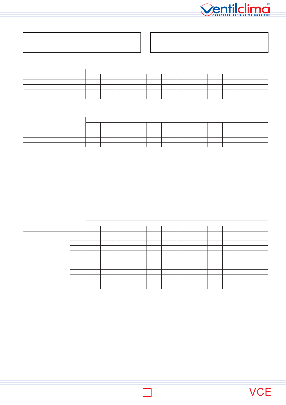
WORK LIMITS
Maximum input water temperature 80 °C
Minimum input water temperature + 4 °C
Maximum input air temperature 32 °C
Minimum input air temperature + 4 °C
Maximum working pressure 8 bar
Water flow and pressure drop limits, 3R coil
Data concern medium water
temperature of 9,5°C
Minimum water flow
Minimum water pressure drop
Maximum water flow
Maximum water pressure drop
VCE10 VCE20 VCE30 VCE40 VCE50 VCE60 VCE70 VCE80 VCE90 VCE100 VCE110 VCE120
l/h 125 100 100 100 100 100 75 125 125 200 275 275
kPa 0,6 0,4 0,5 0,5 0,6 0,6 0,5 0,5 0,5 0,6 0,5 0,6
l/h 1.275 1.200 1.125 1.150 1.025 1.000 850 1.400 1.400 2.075 2.900 2.850
kPa 58,6 59,5 59,6 61,2 59,2 59,0 62,0 59,1 60,1 60,6 60,6 60,4
MODEL
Water flow and pressure drop limits, 1R coil
Data concern medium water
temperature of 65°C
Minimum water flow
Minimum water pressure drop
Maximum water flow
Maximum water pressure drop
VCE10 VCE20 VCE30 VCE40 VCE50 VCE60 VCE70 VCE80 VCE90 VCE100 VCE110 VCE120
l/h 150 150 125 125 125 125 125 100 100 125 125 125
kPa 0,6 0,6 0,5 0,5 0,6 0,5 0,6 0,6 0,5 0,5 0,5 0,5
l/h 1.550 1.500 1.400 1.375 1.275 1.350 1.225 1.100 1.100 1.375 1.325 1.325
kPa 60,7 59,3 60,3 61,0 61,0 60,4 59,5 59,0 60,1 59,6 59,7 58,8
3 way valves
Using of 2 or 3 way valves is compulsory when the unit is used for cooling to avoid condensate in the external structure (bearing structure and cabinet). As alternative
install a regulating system to stop coil water entering when the fan is off.
MODEL
Maximal fan static pressure
When the unit is connected with ducts fan air flow is reduced due to the ducting pressure drops.
With very high pressure drops fancoil air flow becomes too low and electric motor which is connected to the fan can be damaged. For this reason we recomand static
pressures lower than the maximal limit static pressures indicated in the schedule.
NOTE: when the fancoil is operating with the maximal operating indicated static pressure value, air flow is half in comparison with the unit without ducts at the same
working speed.
Definitively the static pressure limit value corresponds to the back pressure ables to halve fancoil air flow (as a consequence the fancoil unit performances like heating
& cooling capacity, will be reduced of about 50%).
2 pipe system
4 pipe system
MODELLO
VCE10 VCE20 VCE30 VCE40 VCE50 VCE60 VCE70 VCE80 VCE90 VCE100 VCE110 VCE120
Pa 1 9 12 7 9 19
Pa 2 11
Pa 3 15 19
Pa 4 18
Pa 5 25
Pa632403237 4945 547060 84
Pa 1 8 10 6 8 14
Pa 2 9
Pa 3 11 15
Pa 4 15
Pa 5 19
Pa625322430 3835 446051 82
min
15
med
25
max
32 25 27
min
12
med
19
max
25 19 22
min
med
max
min
med
max
10
15
19
8
13
15
min
min
med
max
med
max
min
11
med
17
22 32
max
min
9
med
14
17 25
max
min
22 16
med
28
max
40 36
min
17 13
med
21
max
32 28
12 15 41
min
19 51
22 26
med
28
max
10 11 30
min
18 20
med
22
max
min
34
med
max
44
15 38
min
28
med
max
36
min
med
max
55
60 49 68 76 80
65 53
min
med
max
42
50 40 67 75 79
55 44
min
33
41 49
45
med
max
min
27
33 48
37
med
max
44 37 47
min
47
62
med
68
max
75
84
43 37 47
min
47
61
med
67
max
74
83
min
med
max
min
med
max
58
84
58
82
74
73
min
med
max
min
med
max
TECHNICAL MANUAL
Data indicated as min, med, max, concern the 3 standard speeds set at the factory. upon customer request other 3 speeds among the 6 speeds
available can be connected.
range
7
ISO 9001:2000 - Cert. n. 1368/1
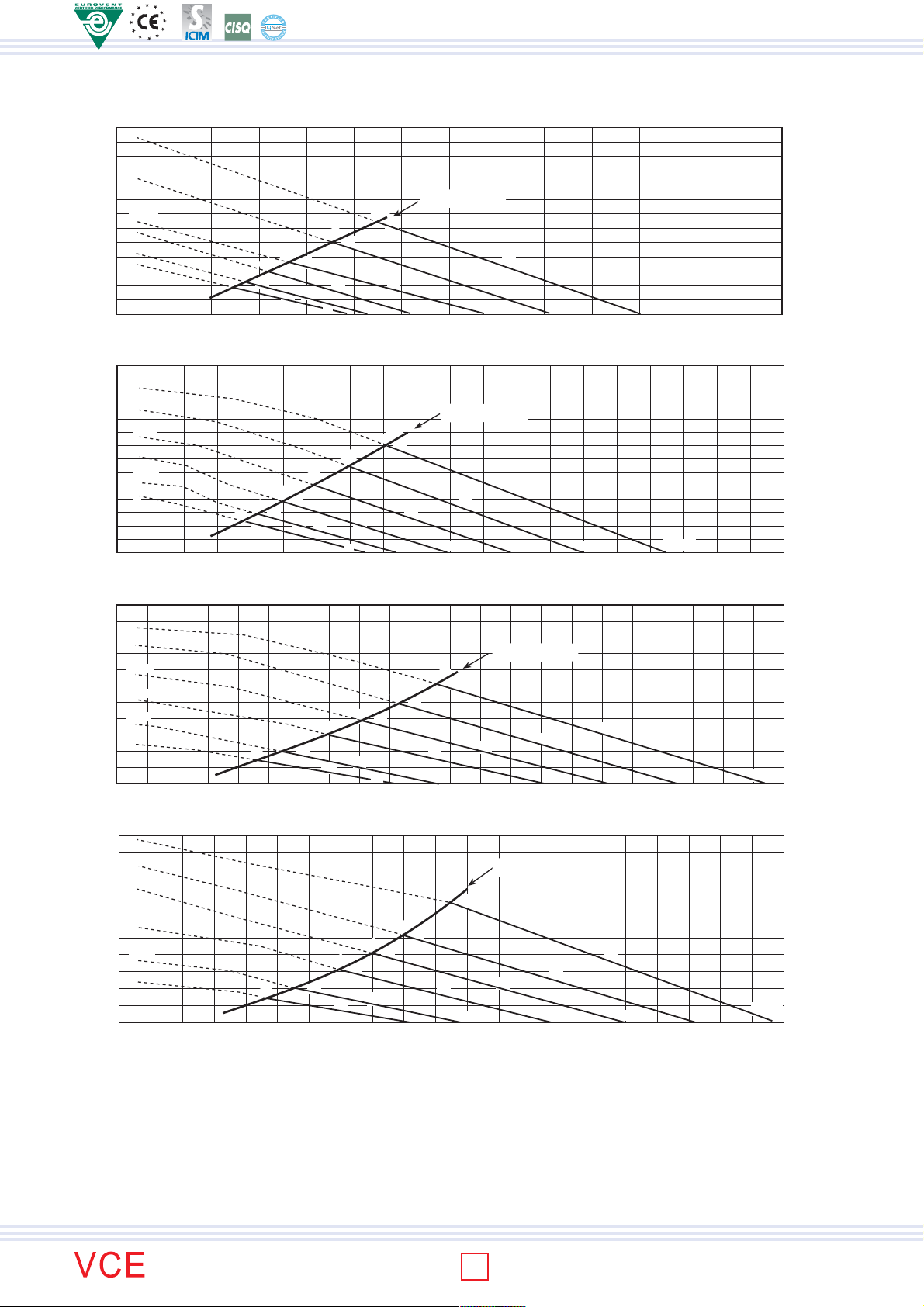
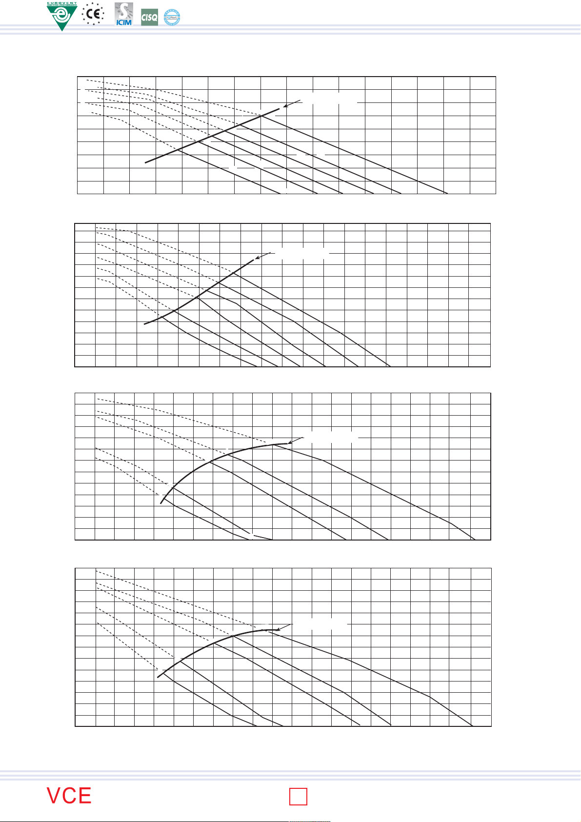
AERAULIC PERFORMANCES
MOD.: VCE 10 - 2 PIPE SYSTEM (3 Row coil data)
6
60
50
5=MAX
40
4=MED
30
3
2=MIN
20
1
10
Available static pressure - (Pa)
0
TECHNICAL MANUAL
0 50 100 150 200 250 300
9
33
18
15
42
11
37
32
MOD.: VCE 20 - 2 PIPE SYSTEM (3 Row coil data)
6
60
5
50
4=MAX
40
3=MED
30
2=MIN
20
1
10
19
15
43
12
41
Available static pressure - (Pa)
0
0 50 100 150 200 250 300 350 400 450
MOD.: VCE 30 - 2 PIPE SYSTEM (3 Row coil data)
50
6
5
40
4=MAX
30
3=MED
2=MIN
20
1
10
Available static pressure - (Pa)
0
0 50 100 150 200 250 300 350 400 450
10
7
39
Working limits
32 Pa
25
47
39
35
32
57
51
44
33
48
54
464137
51 dB(A)
Air flow (m3/h)
Working limits
40 Pa
32
25
51
49
40
36
32
56
55
44
48
52
55
49444036
53 dB(A)
Air flow (m3/h)
Working limits
32 Pa
58
25
19
15
51
43
38
34
56
54
45
30
49
33
52
55
500
51 dB(A)
Air flow (m
3
/h)
474440
MOD.: VCE 40 - 2 PIPE SYSTEM (3 Row coil data)
6
50
5=MAX
4
40
30
3=MED
22
2=MIN
20
1
10
Available static pressure - (Pa)
0
0 50 100 150 200 250 300 350 400 450
9
39
17
11
43
34
54
51
38
37 Pa
27
56
45
30
57
33
Working limits
49
52
54
474440
50 dB(A)
500
Air flow (m
3
/h)
Data indicated as min, med, max, concern the 3 standard speeds set at the factory. upon customer request other 3 speeds among the 6 speeds
available can be connected.
range
8
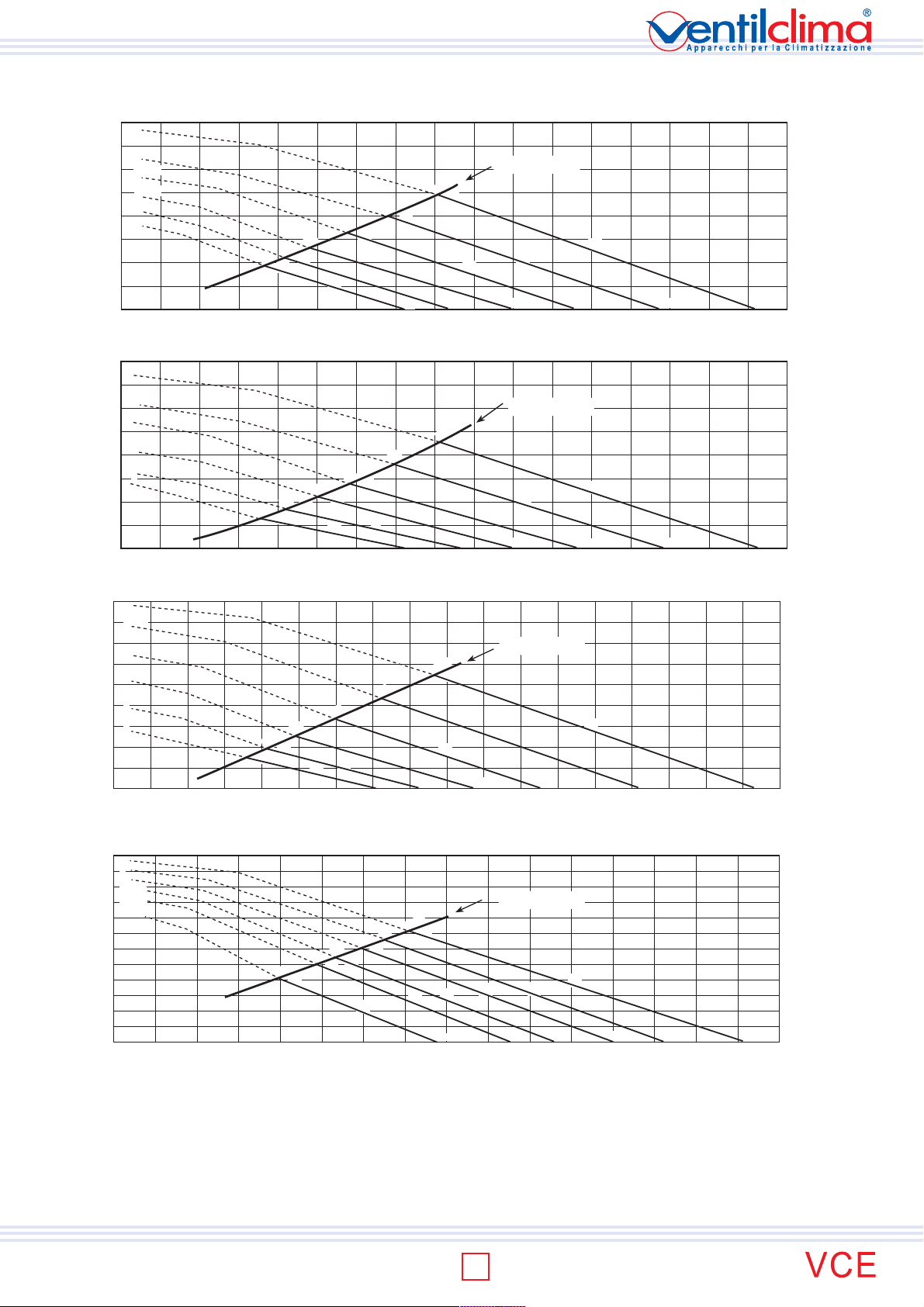
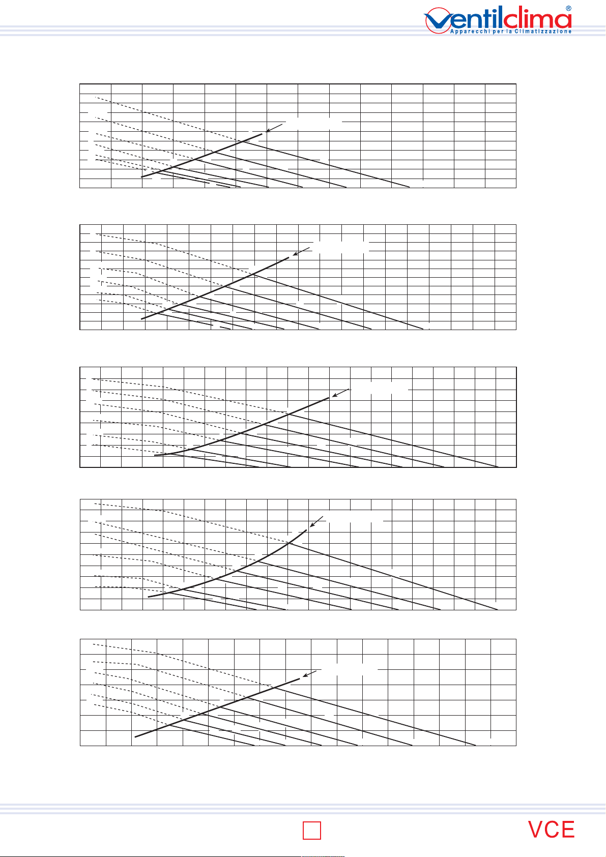
AERAULIC PERFORMANCES
MOD.: VCE 50 - 2 PIPE SYSTEM (3 Row coil data)
6
70
5
60
4=MAX
50
3=MED
2
40
1=MIN
30
20
10
Available static pressure - (Pa)
49 Pa
63
40
32
28
57
22
52
19
51
46
59
58
50
47
37
39
52
Working limits
56
43
59
47
0 100 200 300 400 500 600 700 800
MOD.: VCE 60 - 2 PIPE SYSTEM (3 Row coil data)
6
70
5=MAX
60
4=MED
50
3
40
2=MIN
30
1
20
10
Available static pressure - (Pa)
0
0 100 200 300 400 500 600 700 800
16
51
12
48
28
58
22
56
46
43
45 Pa
64
36
60
52
49
34
38
Working limits
57
42
60
47
51
52
56 dB(A)
Air flow (m
57 dB(A)
3
/h)
Air flow (m3/h)
MOD.: VCE 70 - 2 PIPE SYSTEM (3 Row coil data)
6
5=MAX
80
70
4=MED
60
3=MIN
50
2
40
30
1
20
10
Available static pressure - (Pa)
0
0 100 200 300 400 500 600 700 800
15
26
55
19
50
45
40
44
34
59
49
44
36
54 Pa
63
62
53
38
Working limits
57
42
60
46
MOD.: VCE 80 - 2 PIPE SYSTEM (3 Row coil data)
6
5
110
4
100
3=MAX
2=MED
90
1=MIN
80
70
60
50
40
41
64
30
20
10
Available static pressure - (Pa)
0
0 200 400 500 700 900 1100 1300 1400
100 300 600 800 1000 1200 1500
60
55
67
51
66
57
70 Pa
70
65
69
68
62
61
51
Working limits
64
56
68
66
58
61
52
57 dB(A)
Air flow (m
3
/h)
TECHNICAL MANUAL
64
67 dB(A)
Air flow (m
3
/h)
Data indicated as min, med, max, concern the 3 standard speeds set at the factory. upon customer request other 3 speeds among the 6 speeds
available can be connected.
range
9
ISO 9001:2000 - Cert. n. 1368/1
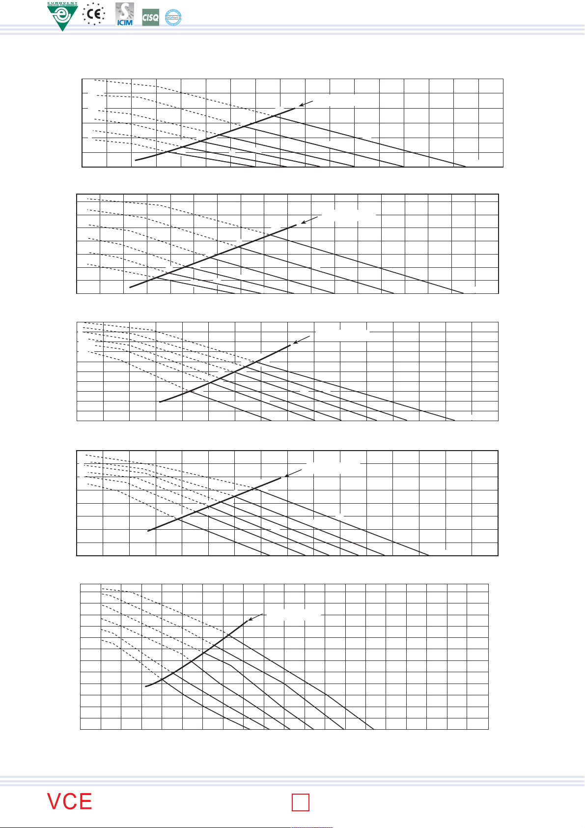
AERAULIC PERFORMANCES
MOD.: VCE 90 - 2 PIPE SYSTEM (3 Row coil data)
6
5=MAX
80
4
3=MED
70
2
1=MIN
60
50
40
33
30
20
10
Available static pressure - (Pa)
0
0 200 400 500 700 900 1100 1300 1400
100 300 600 800 1000 1200 1500
TECHNICAL MANUAL
MOD.: VCE 100 - 2 PIPE SYSTEM (3 Row coil data)
Available static pressure - (Pa)
MOD.: VCE 110 - 2 PIPE SYSTEM (3 Row coil data)
Available static pressure - (Pa)
120
110
100
120
110
100
6
5=MAX
4
3=MED
90
2=MIN
80
1
70
60
50
40
49
66
44
64
30
20
10
0
5=MAX
3=MED
90
2=MIN
80
70
200 400 600 800 1000 1200 1400 1600
4
1
60
50
40
47
65
37
62
30
20
10
0
200 400 600 800 1000 1200 1400 1600
Working limits
60 Pa
70
53
69
49
68
45
67
41
66
62
62
60
56
51
66
64
55
68
64
58
61
67 dB(A)
Air flow (m
3
/h)
Working limits
84 Pa
71
75
71
68
69
62
68
69
68
65
63
61
57
52 55
76
68
51
69Q
69
61
84 Pa
47 50 58 61 67
57
60 63 65 dB(A)
1800
Working limits
71
67
66
70
1800
dB(A)
2000
Air flow (m3/h)
Air flow (m3/h)
MOD.: VCE 120 - 2 PIPE SYSTEM (3 Row coil data)
5=MAX
130
4=MED
3
120
110
2=MIN
100
1
90
80
70
60
50
40
30
Available static pressure - (Pa)
20
10
0
200 400 600 800 1000 1200 1400 1600
84 Pa
80
74
58
64
47
63
57
69
68
60
49 51 59 61 66 dB(A)
Working limits
71
65
66
69
Air flow (m3/h)
1800
2000
Data indicated as min, med, max, concern the 3 standard speeds set at the factory. upon customer request other 3 speeds among the 6 speeds
available can be connected.
range
10
AERAULIC PERFORMANCES
MOD.: VCE 10 - 4 PIPE SYSTEM (3+1 Row coil data)
50
6
40
5=MAX
36
59
Working limits
47
Working limits
55
43
53
4540
58
47
52
50 dB(A)
4=MED
30
3
20
2=MIN
1
10
0
Available static pressure - (Pa)
0 50 100 150 200 250 300
9
8
32
15
11
38
46
41
36
31
31
25 Pa
19
38
56
50
43
34
MOD.: VCE 20 - 4 PIPE SYSTEM (3+1 Row coil data)
60
6
50
5
40
4=MAX
3=MED
30
2=MIN
20
1
10
0
Available static pressure - (Pa)
0 50 100 150 200 250 300 350 400 450
12
10
43
19
54
15
52
45
42
38
34
32 Pa
25
58
51
47
38
56 dB(A)
Air flow (m3/h)
Air flow (m
3
/h)
MOD.: VCE 30 - 4 PIPE SYSTEM (3+1 Row coil data)
40
6
5
4=MAX
30
3=MED
20
2=MIN
1
10
0
Available static pressure - (Pa)
0 50 100 150 200 250 300 350 400 450
MOD.: VCE 40 - 4 PIPE SYSTEM (3+1 Row coil data)
Available static pressure - (Pa)
6
5=MAX
40
4
30
3=MED
20
2=MIN
1
10
0
0 50 100 150 200 250 300 350 400 450
8
6
8
44
39
9
45
39
15
13
34
14
34
54
51
39
22
17
55
53
40
30
24 Pa
19
30
57
57
56
34
30 Pa
49
59
50
45
47
35
Working limits
52
40
Working limits
53
42
54
44
56
45
MOD.: VCE 50 - 4 PIPE SYSTEM (3+1 Row coil data)
6
60
5
50
4=MAX
3=MED
40
2
30
1=MIN
20
10
0
Available static pressure - (Pa)
0 100 200 300 400 500 600 700 800
17
14
49
25
57
21
56
51
46
44
38 Pa
32
63
59
51
49
35
38
Working limits
56
42
46
59
51
56 dB(A)
50 dB(A)
Air flow (m
52 dB(A)
Air flow (m
Air flow (m
3
/h)
3
/h)
3
/h)
TECHNICAL MANUAL
47
48
Data indicated as min, med, max, concern the 3 standard speeds set at the factory. upon customer request other 3 speeds among the 6 speeds
available can be connected.
range
11
ISO 9001:2000 - Cert. n. 1368/1
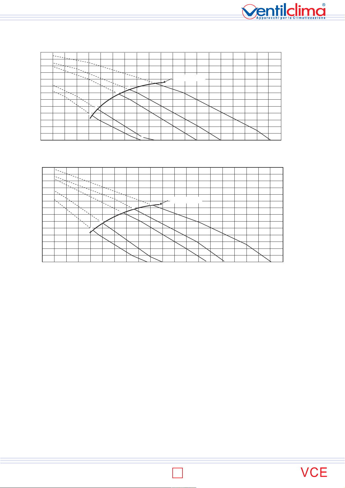
AERAULIC PERFORMANCES
MOD.: VCE 60 - 4 PIPE SYSTEM (3+1 Row coil data)
6
5=MAX
50
4=MED
40
3
30
2=MIN
20
1
10
0
0 100 200 300 400 500 600 700 800
Available static pressure - (Pa)
13
10
52
MOD.: VCE 70 - 4 PIPE SYSTEM (3+1 Row coil data)
6
70
TECHNICAL MANUAL
5=MAX
60
4=MED
50
3=MIN
40
2
30
1
20
10
0
Available static pressure - (Pa)
0 100 200 300 400 500 600 700 800
MOD.: VCE 80 - 4 PIPE SYSTEM (3+1 Row coil data)
6
5
90
4
3=MAX
80
2=MED
1=MIN
70
15
51
11
45
60
50
40
30
20
10
0
Available static pressure - (Pa)
0 200 400 500 700 900 1100 1300 1400
100 300 600 800 1000 1200 1500
Working limits
35 Pa
28
22
18
54
59
58
49
47
64
61
53
51
38
41
58
44
60
48
53
57 dB(A)
Air flow (m
3
/h)
Working limits
44 Pa
36
28
20
56
45
40
63
60
50
36
64
54
39
58
43
61
47
53
58 dB(A)
Air flow (m3/h)
Working limits
60 Pa
71
55
70
50
69
42
68
38
67
30
64
57
62
51
65
63
57
69
67
59
62
65
68 dB(A)
Air flow (m
3
/h)
MOD.: VCE 90 - 4 PIPE SYSTEM (3+1 Row coil data)
6
5=MAX
70
4
3=MED
2
60
1=MIN
50
40
30
27
62
40
37
68
33
67
20
10
Available static pressure - (Pa)
0
0 200 400 500 700 900 1100 1300 1400
100 300 600 800 1000 1200 1500
51 Pa
71
44
70
69
63
61
56
51
Working limits
67
65
56
69
62
59
65
68 dB(A)
Air flow (m
3
/h)
MOD.: VCE 100 - 4 PIPE SYSTEM (3+1 Row coil data)
6
120
5=MAX
110
4
100
3=MED
90
2=MIN
80
1
70
60
50
40
30
Available static pressure - (Pa)
20
61
69
48
66
43
65
82 Pa
72
74
71
67
70
64
61
58
10
0
200 400 600 800 1000 1200 1400 1600
Data indicated as min, med, max, concern the 3 standard speeds set at the factory. upon customer request other 3 speeds among the 6 speeds
available can be connected.
66
53 55
Working limits
70
68
58
61 63 66
dB(A)
1800
Air flow (m
3
/h)
range
12
AERAULIC PERFORMANCES
MOD.: VCE 110 - 4 PIPE SYSTEM (3+1 Row coil data)
130
5=MAX
120
4
110
3=MED
100
90
2=MIN
80
1
70
75
67
70
69
60
50
40
30
Available static pressure - (Pa)
20
47
66
37
63
62
52
10
0
200 400 600 800 1000 1200 1400 1600
MOD.: VCE 120 - 4 PIPE SYSTEM (3+1 Row coil data)
140
5=MAX
130
4=MED
3
120
110
2=MIN
100
1
90
80
70
60
50
40
30
Available static pressure - (Pa)
20
10
0
200 400 600 800 1000 1200 1400 1600
58
65
47
63
79
73
69
61
57
83
66
48 51 58 62 67
82 Pa
70
72
49 52 60 62 67 dB(A)
71
68
Working limits
66
Working limits
67
70
dB(A)
1800
70
1800
2000
2000
Air flow (m3/h)
Air flow (m3/h)
Data indicated as min, med, max, concern the 3 standard speeds set at the factory. upon customer request other 3 speeds among the 6 speeds
available can be connected.
range
13
TECHNICAL MANUAL
ISO 9001:2000 - Cert. n. 1368/1
SOUND POWER SPECTRUM - 2 PIPE SYSTEM
Model Speed
1 33,7 32,7 32,2 24 21,4 14,5 5,6 32
2 Min 33 34,7 32,7 25,9 22,5 14,8 5,8 33
VCE10
VCE20
TECHNICAL MANUAL
VCE30
VCE40
VCE50
VCE60
VCE70
VCE80
VCE90
VCE100
VCE110
VCE120
3 36 37,6 37,1 30,6 25 17,6 6,9 37
4 Med 37,9 41 41 35,4 29,5 21,1 8,8 41
5 Max 42,1 45,1 45,5 40,8 35,6 27,7 16,1 46
6 46,6 49,4 50,2 45,9 41,9 34,8 24,5 51
1 29,2 34,8 31,9 23,5 19,6 14,7 10,1 32
2 Min 33,1 37,8 36 28,8 23,7 17 11,5 36
3 Med 36,9 40,9 40 33,6 28,5 20,9 13,7 40
4 Max 40,2 43,9 43,9 38 33,5 25,2 16,9 44
5 44,7 48,3 48,7 43 39,8 32,2 25,2 49
6 48,8 51,9 51,9 46,9 45,6 37,7 29,9 53
1 31,4 33,4 28,6 20,7 21,6 13,6 13 30
2 Min 32,7 35,5 32,7 25 22,1 14 12,3 33
3 Med 38,2 40,9 39,8 34,3 27,8 18,3 13,8 40
4 Max 41,8 44,1 43,5 38,9 32,4 23,3 16,5 44
5 44,5 46,5 46,2 42,2 36 28,1 19,3 47
6 48,2 50,2 50,1 46,2 40,7 34 26,8 51
1 31,4 33,4 28,6 20,7 21,6 13,6 13 30
2 Min 32,7 35,5 32,7 25 22,1 14 12,3 33
3 Med 38,2 40,9 39,8 34,3 27,8 18,3 13,8 40
4 41,8 44,1 43,5 38,9 32,4 23,3 16,5 44
5 Max 44,5 46,5 46,2 42,2 36 28,1 19,3 47
6 48,2 50,2 50,1 46,2 40,7 34 26,8 50
1 Min 35,3 39,2 35,5 26,3 29,2 25,1 23,9 37
2 37,6 41 38,6 29,9 29,2 25 24,3 39
3 Med 41,5 44,8 42,9 35,3 31,3 26 24,8 43
4 Max 45,1 48 47 40,6 35,2 28 25,2 47
5 49 51,2 50,8 45,2 39,9 32,5 28,6 51
6 53,4 55,6 55,3 50,4 46,3 39,5 31,7 56
1 32,3 36,2 32,5 23,3 26,2 22,1 20,9 34
2 Min 36,6 40 37,6 28,9 28,2 24 23,3 38
3 40,5 43,8 41,9 34,3 30,3 25 23,8 42
4 Med 45,1 48 47 40,6 35,2 28 25,2 47
5 Max 50 52,2 51,8 46,2 40,9 33,5 29,6 52
6 54,4 56,6 56,3 51,4 47,3 40,5 32,7 57
1 34,5 37,2 33,1 26,2 25,3 22,5 19,6 36
2 35,4 40,3 37,1 29,7 27,5 24,2 21,6 38
3 Min 39,7 43,3 41,4 34,5 31,2 26,1 22,3 42
4 Med 43,1 46,9 46 39,8 36,3 28,3 24,8 46
5 Max 48,5 51,3 51,3 45,6 42,4 34,5 27 52
6 53,2 56,2 55,8 51,1 48,6 41,8 32,9 57
1 Min 47,6 50,7 50,3 45,1 41,8 36 29 51
2 Med 52,3 55 55,2 50,2 47,3 41,9 34,3 56
3 Max 53,9 56,9 56,8 52,3 49,7 44,6 37,5 58
4 56,3 59,7 59,5 55,4 53 48,4 42,2 61
5 59,5 62,6 62,1 58,3 56,1 51,8 46,3 64
6 62,5 65,7 64,9 61,4 59,3 55,4 50,7 67
1 Min 48 50,1 50,7 45 41,3 36,2 29,8 51
2 50,7 53,4 54,5 49,1 45,8 40,6 33,4 55
3 Med 53,4 56,2 57 52,4 49,4 44,6 37,6 58
4 55,9 59,1 59,6 55,4 52,7 48,2 42,1 61
5 Max 58,8 61,9 62,4 58,4 55,9 51,7 46,4 64
6 61,3 65 65 61,6 59,2 55,3 50,8 67
1 52,3 53,5 50,8 46,7 40,6 31,9 28,3 52
2 Min 54,7 56,2 53,8 50,1 44,1 35,3 28,5 55
3 Med 56,7 57,8 55,5 52,2 46,8 38,6 30,9 57
4 59,5 60,7 58,1 55,2 50,3 42,9 38,1 60
5 Max 62,1 63,5 60,7 58,3 53,8 46,9 39,9 63
6 63,3 65,7 62,5 60,2 56,1 49,7 43 65
1 50,4 49,1 46 41,3 34,1 26,6 24,1 47
2 Min 52,9 51,6 49 44,7 37,8 29,1 23,6 50
3 Med 60,2 58,8 56,4 53,1 47,7 39,7 31,6 58
4 62,1 61,6 59 56,2 51,4 44,2 37,7 61
5 Max 67,1 67,1 64,4 62,2 58,3 52,3 46,1 67
1 52,8 51,1 47,5 43,5 36,7 29,4 25,7 49
2 Min 54,7 52,9 49,6 45,4 39,4 31,3 26,2 51
3 60,7 60,2 57,1 53,8 49,2 41,6 33,8 59
4 Med 62,4 62,2 58,9 55,9 51,6 44,7 37,8 61
5 Max 66,8 66,9 63,2 61,1 57,3 51,5 45,4 66
Standard electric
wiring
Frequence spectrum - ref. octave band (Hz)
125 250 500 1000 2000 4000 8000
Total sound power
dB(A)
Data indicated as min, med, max, concern the 3 standard speeds set at the factory. upon customer request other 3 speeds among the 6 speeds
available can be connected.
range
14
SOUND POWER SPECTRUM - 2 PIPE SYSTEM
Model Speed
VCE10
VCE20
VCE30
VCE40
VCE50
VCE60
VCE70
VCE80
VCE90
VCE100
VCE110
VCE120
Standard electric
wiring
1 32,7 31,7 31,2 23 20,4 13,5 4,6 31
2 Min 34 35,7 33,7 26,9 23,5 15,8 6,8 34
3 35 36,6 36,1 29,6 24 16,6 5,9 36
4 Med 36,9 40 40 34,4 28,5 20,1 7,8 40
5 Max 41,1 44,1 44,5 39,8 34,6 26,7 15,1 45
6 45,6 48,4 49,2 44,9 40,9 33,8 23,5 50
1 31,2 36,8 33,9 25,5 21,6 16,7 12,1 34
2 Min 35,1 39,8 38 30,8 25,7 19 13,5 38
3 Med 39,9 43,9 43 36,6 31,5 23,9 16,7 43
4 Max 43,2 46,9 46,9 41 36,5 28,2 19,9 47
5 47,7 51,3 51,7 46 42,8 35,2 28,2 52
6 51,8 54,9 54,9 49,9 48,6 40,7 32,9 56
1 31,4 33,4 28,6 20,7 21,6 13,6 13 30
2 Min 33,7 36,5 33,7 26 23,1 15 13,3 34
3 Med 38,2 40,9 39,8 34,3 27,8 18,3 13,8 40
4 Max 41,8 44,1 43,5 38,9 32,4 23,3 16,5 44
5 44,5 46,5 46,2 42,2 36 28,1 19,3 47
6 47,2 49,2 49,1 45,2 39,7 33 25,8 50
1 31,4 33,4 28,6 20,7 21,6 13,6 13 30
2 Min 34,7 37,5 34,7 27 24,1 16 14,3 35
3 Med 40,2 42,9 41,8 36,3 29,8 20,3 15,8 42
4 42,8 45,1 44,5 39,9 33,4 24,3 17,5 45
5 Max 45,5 47,5 47,2 43,2 37 29,1 20,3 48
6 50,2 52,2 52,1 48,2 42,7 36 28,8 52
1 Min 33,3 37,2 33,5 24,3 27,2 23,1 21,9 35
2 36,6 40 37,6 28,9 28,2 24 23,3 38
3 Med 40,5 43,8 41,9 34,3 30,3 25 23,8 42
4 Max 44,1 47 46 39,6 34,2 27 24,2 46
5 49 51,2 50,8 45,2 39,9 32,5 28,6 51
6 53,4 55,6 55,3 50,4 46,3 39,5 31,7 56
1 36,3 40,2 36,5 27,3 30,2 26,1 24,9 38
2 Min 39,6 43 40,6 31,9 31,2 27 26,3 41
3 42,5 45,8 43,9 36,3 32,3 27 25,8 44
4 Med 46,1 49 48 41,6 36,2 29 26,2 48
5 Max 51 53,2 52,8 47,2 41,9 34,5 30,6 53
6 54,4 56,6 56,3 51,4 47,3 40,5 32,7 57
1 34,5 37,2 33,1 26,2 25,3 22,5 19,6 36
2 36,4 41,3 38,1 30,7 28,5 25,2 22,6 39
3Min40,7 44,3 42,4 35,5 32,2 27,1 23,3 43
4 Med 44,1 47,9 47 40,8 37,3 29,3 25,8 47
5 Max 49,5 52,3 52,3 46,6 43,4 35,5 28 53
6 54,2 57,2 56,8 52,1 49,6 42,8 33,9 58
1Min47,6 50,7 50,3 45,1 41,8 36 29 51
2 Med 53,3 56 56,2 51,2 48,3 42,9 35,3 57
3 Max 54,9 57,9 57,8 53,3 50,7 45,6 38,5 59
4 57,3 60,7 60,5 56,4 54 49,4 43,2 62
5 60,5 63,6 63,1 59,3 57,1 52,8 47,3 65
6 63,5 66,7 65,9 62,4 60,3 56,4 51,7 68
1Min48 50,1 50,7 45 41,3 36,2 29,8 51
2 51,7 54,4 55,5 50,1 46,8 41,6 34,4 56
3 Med 54,4 57,2 58 53,4 50,4 45,6 38,6 59
4 56,9 60,1 60,6 56,4 53,7 49,2 43,1 62
5 Max 59,8 62,9 63,4 59,4 56,9 52,7 47,4 65
6 62,3 66 66 62,6 60,2 56,3 51,8 68
1 53,3 54,5 51,8 47,7 41,6 32,9 29,3 53
2Min54,7 56,2 53,8 50,1 44,1 35,3 28,5 55
3 Med 57,7 58,8 56,5 53,2 47,8 39,6 31,9 58
4 60,5 61,7 59,1 56,2 51,3 43,9 39,1 61
5 Max 62,1 63,5 60,7 58,3 53,8 46,9 39,9 63
6 64,3 66,7 63,5 61,2 57,1 50,7 44 66
1 51,4 50,1 47 42,3 35,1 27,6 25,1 48
2Min53,9 52,6 50 45,7 38,8 30,1 24,6 51
3 Med 60,2 58,8 56,4 53,1 47,7 39,7 31,6 58
4 63,1 62,6 60 57,2 52,4 45,2 38,7 62
5 Max 67,1 67,1 64,4 62,2 58,3 52,3 46,1 67
1 52,8 51,1 47,5 43,5 36,7 29,4 25,7 49
2Min55,7 53,9 50,6 46,4 40,4 32,3 27,2 52
3 61,7 61,2 58,1 54,8 50,2 42,6 34,8 60
4 Med 63,4 63,2 59,9 56,9 52,6 45,7 38,8 62
5 Max 67,8 67,9 64,2 62,1 58,3 52,5 46,4 67
125 250 500 1000 2000 4000 8000
Frequence spectrum - ref. octave band (Hz)
Total sound power
dB(A)
TECHNICAL MANUAL
Data indicated as min, med, max, concern the 3 standard speeds set at the factory. upon customer request other 3 speeds among the 6 speeds
available can be connected.
range
15
 Loading...