

VentilClima UTC 10, UTC 60, UTC 70, UTC 20, UTC 40 Installation, Use And Maintenance Manual
...Page 1
INSTALLATION, USE AND
MAINTENANCE GUIDE
>>
ISO9001:2000 - Cert. n. 1368/1
DUCTABLE AIR TREATMENT UNITS
MI UTC 1105-0 VEN GB
Page 2
ISO 9001:2000 - Cert. n. 1368/1
INTRODUCTION 2
RECOMMENDATIONS 2
IDENTIFICATION OF THE UNIT 2
TRANSPORTATION, RECEIVING, HANDLING 2
Safety provisions 2
DESCRIPTION OF THE UNIT 3
INSTALLATION/USE/MAINTENANCE GUIDE
General size of the base unit 3
General size of the accessories 3
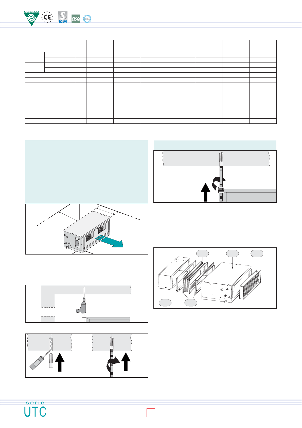
General technical data 4
UNIT INSTALLATION 4
Recommendations for installation 4
Installation of the air treatment unit 4
Installation of the accessories 4-5
WATER CONNECTIONS 6
Connection to the trunk line 6
Condensate water drainage 6
ELECTRICAL CONNECTIONS 6
Recommendations 6
Connections to the terminal blocks: UTC 10-40 6
Connections to the terminal blocks: UTC 50 7
Connections to the terminal blocks: UTC 60 7
Connections to the terminal blocks: UTC 70 8
TURNING THE COIL 8
CLEANING AND MAINTENANCE 9
Routine maintenance 9
Cleaning the air filter 9
WHAT TO DO IF 9
DISMANTLING THE UNIT 9
FIRST PART: FOR THE INSTALLER
SECOND PART: FOR THE USER
INDEX
INTRODUCTION
This installation and maintenance booklet should always accompany the
air treatment unit for ready consultation by the installer or user if necessary.
The unit should be installed in compliance with the regulations in force
in each country and according to the manufacturer's or qualified person's
instructions. The manufacturer cannot be held liable for any damage to
property or injury to persons and animals caused by incorrect installation
of the unit. Only qualified persons should install the unit and connect it
to the mains electricity supply. Before carrying out any work on the unit,
ensure that it is disconnected from the electricity supply. Read this
instruction booklet prior to installation.
RECOMMENDATIONS
This unit is easy to use, but it is important to read all the contents of this
guide before using it for the first time. This will help you to:
- use the unit in all safety
- obtain best performance
- avoid incorrect actions
- respect the environment
-
Do not allow children or unassisted handicapped persons to use the unit.
- Do not touch the unit with wet parts of the body or if barefoot.
- Do not tug, pull or twist electrical cables attached to the unit, even
when disconnected from the electricity supply.
- Do not open the flaps giving access to the internal parts of the unit
without having first put the system on-off switch to "off".
- Do not introduce sharp pointed objects through the air intake and outlet grilles.
- Do not leave packing material (boards, staples, plastic bags, etc.)
within reach of children since they could be a source of danger.
Dispose of correctly.
- Do not spray or throw water directly on the unit.
- Do not use the unit in places with suspended dust/powder or in
potentially explosive atmospheres, in very damp environments or in
the presence of oil in suspension or in particularly aggressive
atmospheres.
- Do not cover the unit with objects or drapes that even partially obstruct
the air flow.
The unit works by electricity at mains voltage (230 Vac, 50 Hz). Always bear
in mind that mains voltage is potentially dangerous and any appliance
connectedto it should be used with caution. Before carrying out any work
on the unit, disconnect it from the electricity supply (by pulling out the plug
from the mains socket or isolating the supply line by putting the on-of switch
OFF. If the unit is not be used for long periods, make sure that the controls
are in the position 0 (off). If the unit is not going to be used in winter when
temperatures are near to freezing, drain the system and ensure that the
unit heat exchanger has no water in it in order to prevent the formation of
ice and consequent breakage. To make the unit inoperable, disconnect it
totally from the electricity supply. It is unsafe to alter or try to alter the
characteristics of this product. Any tampering or alteration in any case makes
the warranty null and void. In the event of malfunction or failure, do not try
to repair the unit yourself; contact a qualified technician. Repairs carried out
by incompetent persons could cause damage or accidents. Always keep
the unit clean. In particular clean the air filter periodically (at least once a
month).
FAILURE TO COMPLY WITH THE ASSEMBLY INSTRUCTIONS
!
GIVEN IN THIS GUIDE RELIEVES THE PRODUCER OF ALL AND
ANY LIABILITY. INCORRECT INSTALLATION COULD CAUSE
MALFUNCTIONING OR FAILURE OF THE UNIT. IT COULD ALSO
REPRESENT A HAZARD FOR THE USER
IDENTIFICATION OF THE UNIT
The air treatment units come with a rating plate, which shows:
- The manufacturer's address - Supply voltage in "V"
- "CE" marking - Supply frequency in "Hz"
- Model - Input in "W"
- Lot number - Total cooling capacity in "W"
- Date of production - Sensible cooling capacity in "W"
- Rated absorbed current in "A" - Heat output.
- Number of phases, indicated with "Ph"
TRANSPORTATION, RECEIVING, HANDLING
The units and their accessories are enclosed in cardboard boxes up to
size 50, while the other sizes are palletised. The packs should be kept
intact until positioned in the final place of installation. Use suitable
handling equipment according to the weight of the unit, as provided for
by directive 89/391/EEC and subsequent amendments. The weight of
each single machine is given in this guide (table 2). Upon receiving the
unit, check all the parts for any damage caused in transit. Any damage
should be reported to the carrier by affixing an accepted with reservation
on the accompanying note, specifying the type of damage. In the event
of prolonged storage, keep the units protected against dust and far from
sources of vibration or heat. The number of units that may be positioned
on one pallet are given in the table (table 1).
THE PRODUCER CANNOT BE HELD LIABLE FOR DAMAGE
!
DUE TO INCORRECT HANDLING OR LACK OF PROTECTION
AGAINST THE ELEMENTS.
SAFETY PROVISIONS
-
Secure packs during transportation.
- Do not expose to the elements.
- Do not tread on packs.
- Protect hands with work gloves when dismantling the unit.
- Work in PAIRS if the appliance weighs more than 25 kg.
2
Page 3
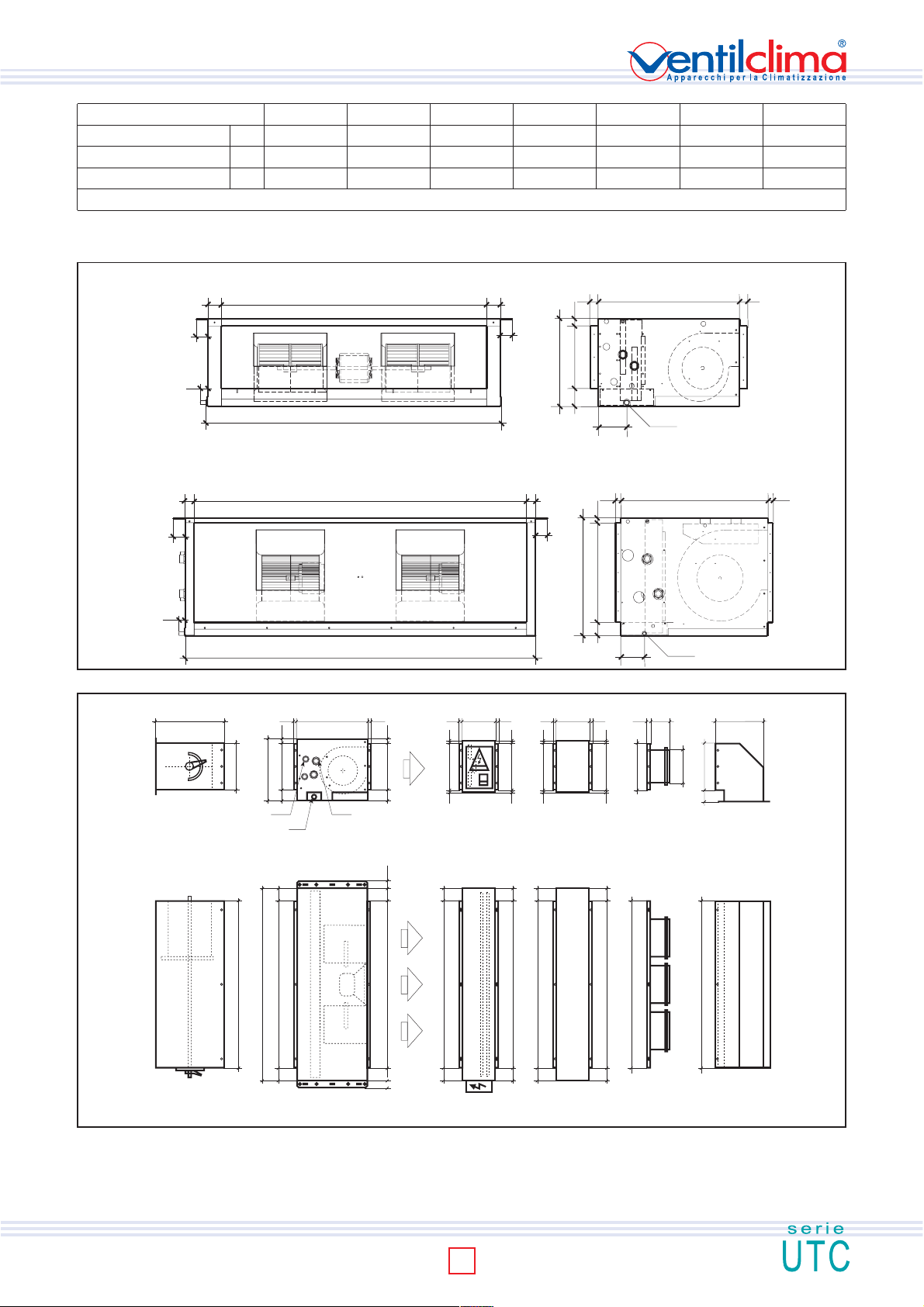
MODEL U.M. UTC 10 UTC 20 UTC 30 UTC 40 UTC 50 UTC 60 UTC 70
Unit overall dim.
Max. number per pallet
Pallet size
mm 650x533x299 1.000x533x299 1.100x533x324 1.339x533x324 1.339x533x374 1.341x853x674 2.028x853x674
N. 10 5 5 5 5 2 2
140x80 120x80 120x80 150x80 150x80 150x100 230x100
N.B.: the units may be stacked up to a maximum of 1.80 m in height
DESCRIPTION OF THE UNIT
GENERAL SIZE OF THE BASE UNIT
MODELS UTC 10, 20, 30, 40, 50
P
Ø 20
29
P
29
44
51
37
44
51
B
51
29
26
44
A
H
76
L
107
MODELS UTC 60, 70
B
51
44
29
26
Tab. 1
37
GENERAL SIZE OF DUCTWORK ACCESSORIES
400
2929
26
A
A
H
76
SSP SRE PA M BAM RAM
L
B
B 5151
P
C
ØAFØA
ØC
BASE UNIT
A
H
76
Ø 20
L
2042626
26A76
A 1111
4444
51
B
B 5050
A 1111
50
B
2042626
A 1111
B 5050
107
A 111170A
50
B
B
Fig. 1
30
ØBAM
341
A115
B
51
50
50
INSTALLATION/USE/MAINTENANCE GUIDE
Fig. 2
3
Page 4
ISO 9001:2000 - Cert. n. 1368/1
GENERAL TECNICHAL DATA
MODELLO UTC 10 UTC 20 UTC 30 UTC 40 UTC 50 UTC 60 UTC 70
Fans - Motors No.
Standard Rows No.
coil Fittings (ØAF) Ø
Auxiliary Rows No.
coil Fittings (ØAC) Ø
INSTALLATION/USE/MAINTENANCE GUIDE
Cond. drain fitting (ØC) Ø mm
High (H) mm
Lenght (L) mm
Depht (P) mm
N. x Ø BAM mm
Net Weight kg
Max.power motor input W
Max.current motor input A
(A) mm
(B) mm
UNIT INSTALLATION
RECOMMENDATIONS FOR INSTALLATION!
Before installing the unit, ensure that:
1) the place of installation has sufficient space for carrying out installation as well as routine
and extraordinary maintenance work (see fig. 3). If the unit is installed behind a
suspended ceiling, an access should be provided;
2) there are no obstructions for air intake and delivery;
3) the water fittings are of the sizes, in the position and spaced apart as required by the
unit;
4) the system pressure does not exceed 8 bar for the water-filled versions;
5) the electricity supply corresponds to the data on the unit rating plate and that there is
a circuit breaker switch readily accessible to the user to cut off the power supply
whenever necessary;
6) the circuit breaker is in the OFF position so that there is no voltage on the unit supply
line.
1,5 P
INSTALLATION OF THE AIR TREATMENT UNIT
Preliminary operations:
- check that the various unit components are perfectly intact;
- check that the installation accessories and documentation are in the pack;
- place the packed section as close as possible to the place of installation;
- do not place tools or weights of any kind on the packed unit.
1-1 2-1 2-1 2-1 2-1 1-1 2-2
333 33 44
1/2" 1/2" 3/4" 3/4" 1" 1"1/4 1"1/2
111 11 22
1/2" 1/2" 1/2" 1/2" 3/4" 1" 1"1/4
20 20 20 20 20 20 20
299 299 324 324 374 674 674
650 1.000 1.100 1.339 1.339 1.341 2.028
533 533 533 533 533 853 853
197 197 222 222 272 572 572
548 898 998 1.237 1.237 1.239 1.926
2xØ200 3xØ200 3xØ200 4xØ200 4xØ200 2xØ200 4xØ200
28 26 41 46 57 117 192
162 218 322 340 582 1.320 2.600
0,72 0,97 1,43 1,51 2,58 5,86 11,54
P
Electrical supply: 230 V/1/50 Hz
possible noise being created by vibrations from the unit, it is advisable to insert a vibrationdamping joint.
N.B.: the screw anchors, threaded rods and whatever else is necessary for accomplishing
the installation are NOT included in the supply of the air treatment unit.
Fig. 6
INSTALLATION OF THE ACCESSORIES
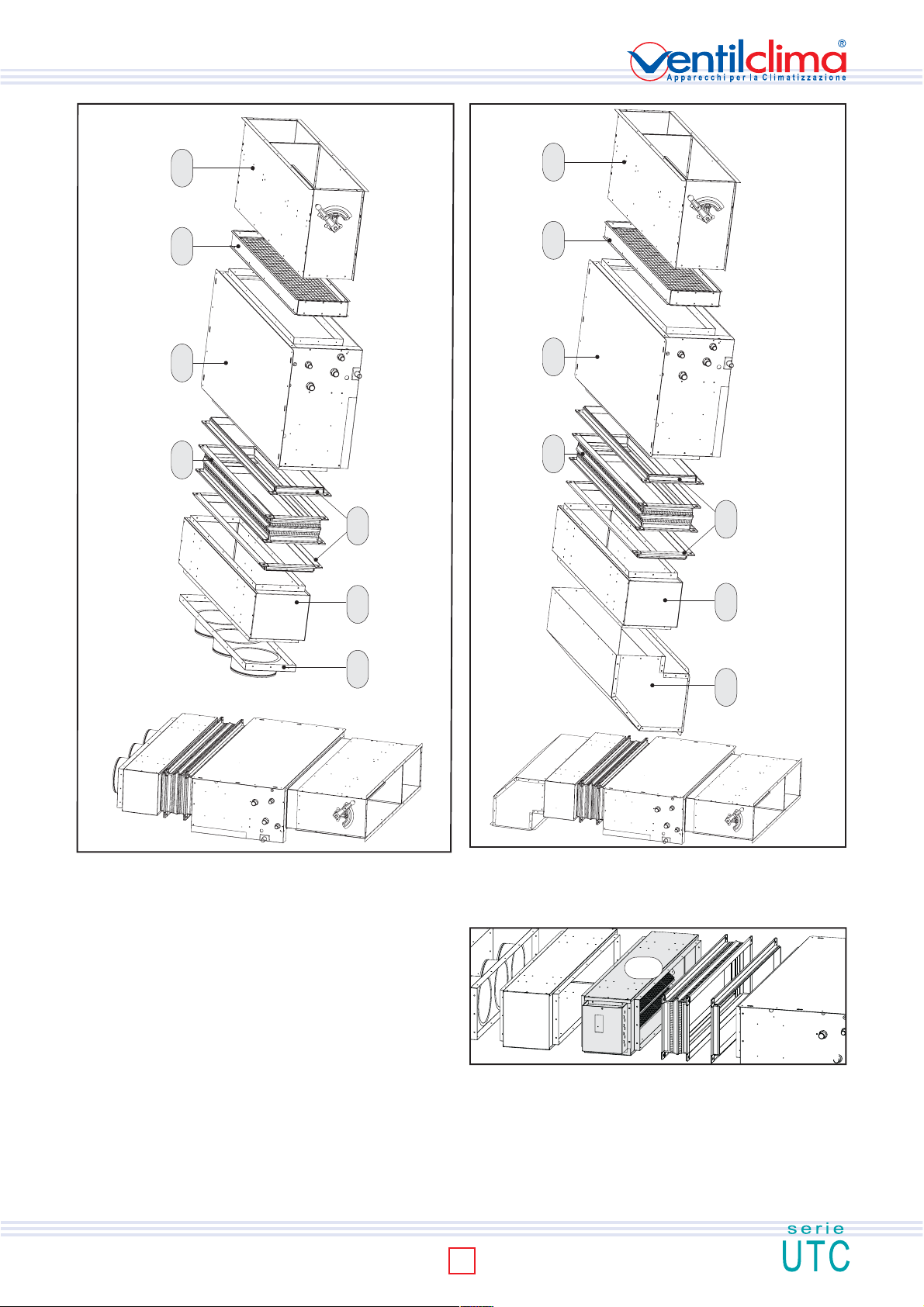
Some examples are given below of assembling the accessories for ducted air
treatment units.
Example 1
First of all put the air filter section (SFA) on the unit intake, inserting it into the special
rim (male-female) and fixing it with the galvanised self-tapping screws 4.2x9.5.
Proceed as described above on the delivery end with the connecting flange (FAM).
Put the vibration isolation joint (GAM) on the flange and fix it using the cheeseheaded screws M8x16 and hexagon bolts.
Fig. 3
GAM
UTC SFA
Tab. 2
Fig. 4
Drill the holes in line with the relative slots for the 6 unit screw anchors (fig. 4). Inject
thermosetting resin into the holes and then insert the screw anchors (fig. 5).
Fig. 5
Fix the threaded rods of the correct length to the screw anchors (fig. 5) and insert them
into the relative slots (fig. 6). After having created a slope (max. 3 cm/m) in the direction
of the condensate outlet, lock the threaded rod with a nut and check nut. To prevent
PAM FAM
Example 2
Proceed by inserting the manual air intake section (SSP) into the air filter section (SFA) by
means of the male-female coupling. After having secured it with the self-tapping screws (4.2
x 9.5 galvanised), anchor it to the ceiling as illustrated for the base unit in figures 4-7. Put
another connecting flange on the vibration isolation joint (GAM) and secure it using cheeseheaded screws M8x16 and hexagon bolts. Insert the straight delivery plenum (PAM) in the
connecting flange and fix it using galvanised self-tapping screws 4.2 x 9.5. Connect the air
delivery union with round fittings (BAM) with the procedure described above.
4
Fig. 7
Page 5
UTC SFA SSP
UTC SFA SSP
GAM
PAM FAM
BAM
Fig. 8
Esempio 3
A 90° plenum (RAM) may be used instead of the air delivery union for better
direction of airflow. Insert the manual air intake section (SSP) in the air filter
section (SFA) by means of the male-female coupling. After having secured it
with the self-tapping screws (4.2 x 9.5 galvanised), anchor it to the ceiling as
illustrated for the base unit in figures 4-7. Put another connecting flange on the
vibration isolation joint (GAM) and secure it using cheese-headed screws M8x16
and hexagon bolts.Insert the straight delivery plenum (PAM) in the connecting
flange and fix it using galvanised self-tapping screws 4.2 x 9.5. Then connect
the 90° plenum (RAM) with the procedure described above.
Esempio 4
La sezione di riscaldamento con resistenza elettrica (SRE) viene di solito posizionata in
mandata prima del plenumdritto di mandata (PAM). Può essere utilizzata indifferentemente
con il bocchettone di mandata (BAM) o con il plenum a 90° di mandata (RAM). L'aggancio
è di tipo maschio-femmina con fissaggio mediante viti autoforanti 4,2 x 9,5 zincate.
GAM
PAM FAM
RAM
Fig. 09
SRE
5
Example 4 - The heating section with electric heating element (SRE) is usually placed
Fig. 10
INSTALLATION/USE/MAINTENANCE GUIDE
Page 6
ISO 9001:2000 - Cert. n. 1368/1
HYDRAULIC CONNECTION
MAIN HYDRAULIC CONNECTION
INSTALLATION/USE/MAINTENANCE GUIDE
IN
OUT
IN
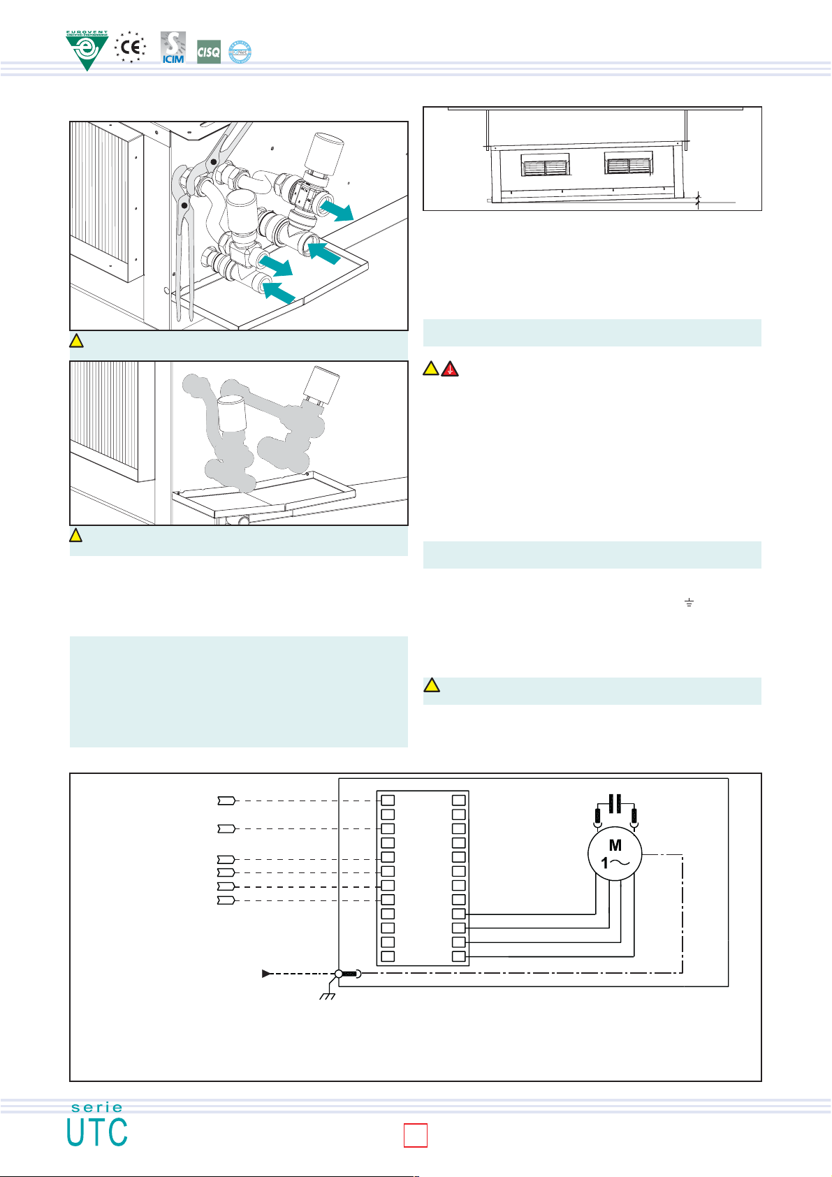
CAUTION! Always use a wrench and counter-wrench for connection
!
of the coil to the pipes (fig. 11).
CAUTION! If the valve is installed, suitably insulate the valve body with insulating
!
material (fig. 12).
Connect the water inlet and outlet pipes, observing the indications given on the side of
the unit. Correctly insulate the water supply pipes to prevent dripping during the cooling
mode of operation. A shutoff valve should be inserted on the water supply pipe and a
balancing valve on the outlet pipe. The valve body and balancing valve should also be
properly insulated to prevent dripping. It is the installer's responsibility to insulate properly
and the manufacturer cannot be held liable for any insulation work.
N.B.: It is always advisable to install the valve.
the valve reduces consumption because upon reaching the set temperature the
circulation of water is stopped to avoid wasting energy (the fan coil would otherwise
continue to heat like a radiator, even with the motor at a standstill). In the cooling
mode of operation the valve stops the circulation of water when the set
temperature is reached, this stopping the internal exchanger from continuing
to condense water with possible undesirable dripping onto the floor. It also
reduces chiller operation with consequent energy saving.
In the heating mode of operation
OUT
Fig. 11
Fig. 12
CONDENSATE WATER DRAINAGE
Fig. 13
3 cm/m
The condensate drain pipe should slope downwards by at least 3 cm/m and
should not have ascending or throttled sections in order to ensure a regular flow
of water. It is advisable for a trap to be fitted. The condensate drain pipe should
be connected to a rainwater drainage system. Do not use sewage systems to
avoid possible rising of odours in the event of evaporation of the water in the trap.
Upon completion of work, check that the condensate flows out properly by
pouring water into the tray. The condensate water drainage system should be
fabricated in a workmanlike manner and should be periodically checked.
The manufacturer cannot be held liable for any damage caused by dripping
in the absence of a valve or of periodic maintenance of the drainage system.
ELECTRICAL CONNECTIONS
!
RECOMMENDATIONS
Before carrying out electrical connections, ensure that the electricity supply to the
supply line has been cut off, checking that the on-off switch is in the OFF position.
- Only qualified electricians should carry out the electrical connections.
- Check that the mains supply is single-phase 230 Vac/1/50 Hz (± 10%).
- Operating the unit with voltages outside the above limits could cause malfunction
and renders the warranty null and void.
- The power supply line should be fitted with at least a switch isolator in conformity
with European standard EN60947-3.
- Make sure that the electrical system is suitable for providing not only the working
current required by the unit, but also the necessary current for powering household
and other electrical appliances already in use. Any electrical and mechanical
alterations or tampering render the warranty null and void.
The cables should be sufficiently long so that they are not permanently
taut or create throttling or compression on metal parts.
The power cables should be sufficiently long so that in the event of accidental
tugging the active wires are subjected to stress before the earth wire. Connect
the earth wire to the relative terminal marked with the symbol
the safety regulations in force in the country of installation.
CONNECTIONS TO THE TERMINAL BOARDS
The electrical connections should be made to the terminal boards on the side
of the appliance. Each terminal is identified by the label to be found on the terminal
boards.
CAUTION! FAILURE TO COMPLY WITH THE INDICATED CONNECTIONS
!
MAY CAUSE MOTOR BURNOUT!
. Comply with
WIRING DIAGRAM UTC MOD. 10 - 20 - 30 - 40
N
L
III
Remote
control
230Vac/50Hz
Cross section area= 1,5 mm
LEGENDA
PE Earth (yellow/green) I Minimum speed
M Fan motor II Medium speed
N Neutral III Maximum speed
L Phase SDP/2 Power card
Com Common (white)
2
PE
II
I
Com
SDP/2
5 6 7 8 10 12
13 14 15 16
6
Com
I
II
III
Com
C
III
II
I
UTC
Fig. 14
Page 7
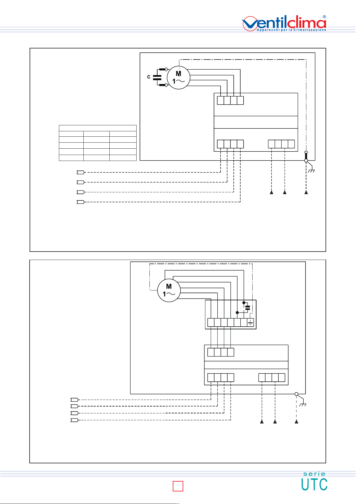
WIRING DIAGRAM UTC MOD. 50
FAN COIL
Com
FAN MOTOR CABLE COLOURS
Min.speed red blue
Med.speed blue black
Max speed black brown
Common white white
Remote control
230Vac/50Hz
LEGENDA
PE Earth (yellow/green) I Minimum speed
M Fan motor II Medium speed
N Neutral III Maximum speed
L Phase SDP Power chart
Com Common (white)
WIRING DIAGRAM UTC MOD. 60
mot. EM mot. EL
Com
I
II
III
Cross section area= 1,5 mm
III
II
I
25 26 27 28
SDP (power chart)
1234
14 15 16 17
2
LN PE
Motor power supply
230Vac/50Hz
Fig. 15
greeen
yellow
blue
brown
orange
black
XA1
Com
Remote control
230Vac/50Hz
LEGENDA
PE Earth (yellow/green) I Minimum speed
M Fan motor II Medium speed
N Neutral III Maximum speed
L Phase SDP Power card
Com Common (white) XA1 Connection box
I
II
III
Cross section area= 1,5 mm
2
min med max Com
brown
black
grey
blue
25 26 27 28
1234
SDP (power chart)
14 15 16 17
LN PE
Motor power supply
230Vac/50Hz
UTC
INSTALLATION/USE/MAINTENANCE GUIDE
Fig. 16
7
Page 8
ISO 9001:2000 - Cert. n. 1368/1
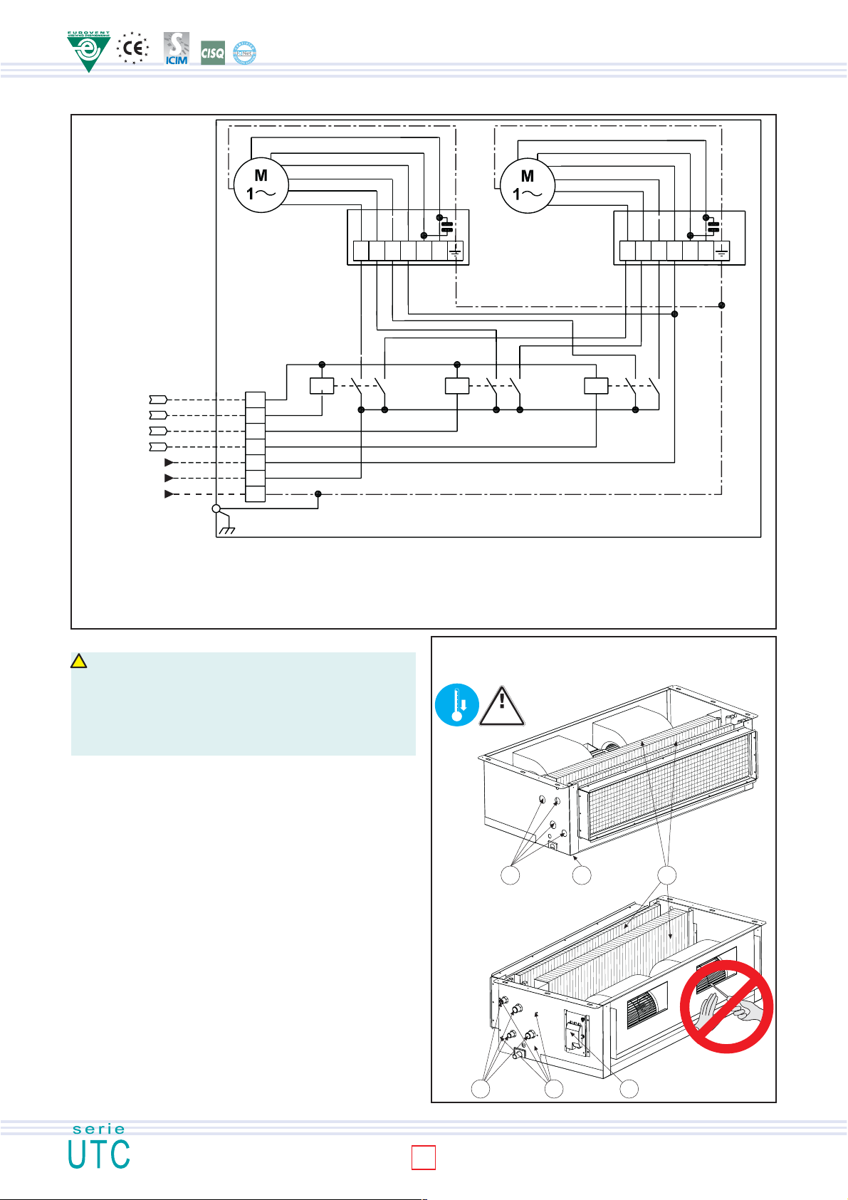
WIRING DIAGRAM UTC MOD. 70
INSTALLATION/USE/MAINTENANCE GUIDE
2
control
Remote
4X1,5 mm
230Vac/50Hz
230Vac/50Hz
3X2,5 mm
Motor power
2
supply
M1
XA3
Com
III
II
I
N
L
PE
green
yellow
green
yellow
blue
red
orange
brown
orange
brown
M2
XA1
min med max Com min med max Com
brown
black
grey
blue
KA1 KA2 KA3
blue
red
XA2
brown
grey
black
UTC
blue
LEGENDA
PE Earth (yellow/green) I Minimum speed
M1-M2 Fan motor II Medium speed
N Neutral III Maximum speed
L Phase SDP Power chart
Com Common (white) XA1-XA2 Connection box
KA1-KA2-KA3 relè 20A/250V type finder 22,22 XA3 Terminal board
TURNING THE COIL
!
CAUTION
The fan wheels may reach the speed of 1,000 rpm. Do not insert objects into the electric
fan and certainly not hands. The motor becomes hot during operation; wait for it to cool
before touching it. During the heating mode of operation the exchanger and the connecting
pipes may become very hot (80°C). Wait for the exchanger to cool before touching it or
protect hands with suitable gloves. The heat exchange water coils are suitable for working
up to a maximum pressure of 8 bar.
To turn the coil, proceed as follows:
1. Disconnect the terminal board (6) from the side of the unit.
2. Remove the condensate collecting tray (2).
3. Remove the coil fixing screws (5).
4. Take out the coil (3), being careful not to be cut by the fins and not to
damage them.
5. Remove the knockouts (1) on the opposite side of the unit (using a
screwdriver) to allow the coil connections to pass through.
6. Position the coil, turning it without tipping it upside down, so that the fittings
are in line with the holes left by the knockouts.
7. Fix the coil using the previously removed screws (5).
8. Shift the terminal board (fixing it to the side opposite the water fittings) and
the motor cables, fixing them with their clamps. Ensure that the cables pass
through the hole in the side of the unit, protecting them with the relative
grommet. If it proves easier to carry out this operation by separating the
wires from the terminal board, mark the positions of the wires to avoid
making mistakes when reconnecting.
9. Reconnect the wires to the relative terminal board (6), taking care that they
are correctly positioned.
10. Replace the condensate collecting tray (2).
60°
0°
P=8
bar max
1 2
Fig. 17
3
45 6
Fig. 18
8
Page 9
R
I
F
I
U
T
I
CLEANING AND MAINTENANCE
CAUTION! Before carrying out any cleaning or maintenance work, disconnect the
Contact a firm specialised in differentiated waste disposal; it is the only way to be certain
of correct recycling and thereby contribute to protection of the environment.
unit from the mains electricity supply!
ROUTINE MAINTENANCE
The user is duty bound to have all maintenance operations carried out by trained and
qualified personnel only. If the unit has to be dismantled, protect hands with work gloves.
Monthly checks:
- Ensure that the fan impellers are clean. If they are dirty, clean them by suction so as not
to damage them.
- Check the whole of the electrical part and in particular that the electrical connections are
tight.
Yearly checks:
- Check the whole of the electrical part and in particular that the electrical connections are
tight.
- Check the tightness of all the bolts, nuts and whatever else may be loosened by the
constant vibrations of the unit.
- Check the motor for dust, dirt or other impurities. Periodically check that the motor works
without unusual vibrations or noise and that the fan inlet is not obstructed, which could
otherwise leading to overheating of the windings.
- Check the fans for dirt or any foreign matter.
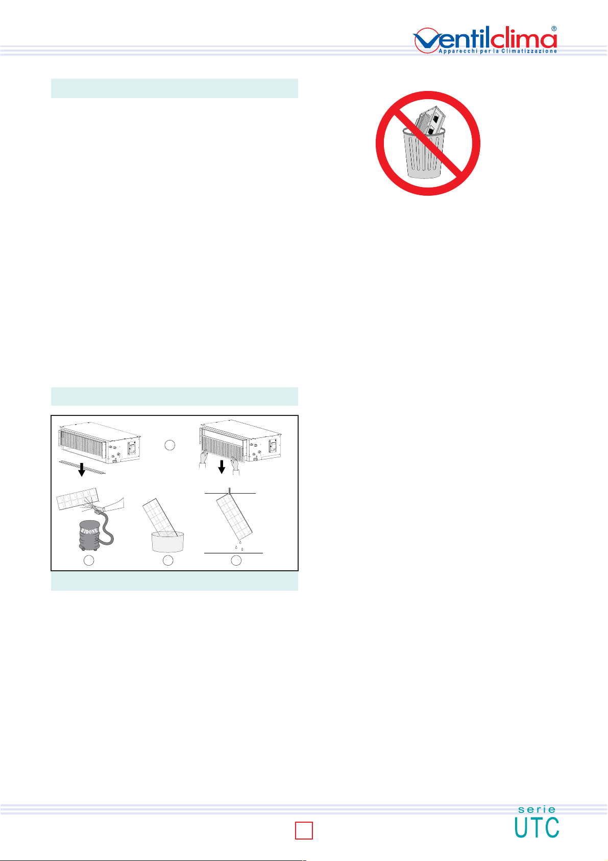
CLEANING THE AIR FILTER
The unit is fitted with an air filter on the fan inlet. During normal operation the filter holds
back impurities in the air.
The filter should be cleaned periodically to keep its filtering properties and the airflow to
the fan unchanged.
It is advisable to clean the filter at least once a month, proceeding as follows.
1. Take out the filter.
2. Place the filter on a flat, dry surface and remove the accumulated dust with a vacuum
cleaner.
3. Wash the filter with water and detergent (no solvents).
4. Leave the filter to dry in a ventilated place in the sun.
5. Replace the filter when it is perfectly dry.
Please clean the air filter every working season of the unit or more frequently
considering the unit activity.
R
I
I
F
T
I
U
1
A
C
A
U
Q
+
D
E
O
T
V
I
E
S
R
432
Fig. 19
N.B.: the filter may also be taken out from the side or from the top.
WHAT TO DO IF...
There is little outflowing air?
- Incorrect speed setting on the control panel (select the right speed).
- Clogged filter (clean the filter)
- Obstruction of the airflow on the intake or delivery line (remove obstruction).
The motor does not turn? Check that
- The power supply is switched on;
- The switches or thermostats are in the correct operating position;
- There is no foreign matter jamming the rotation of the fan.
The unit does not heat/cool as before? Check that
- The filter and the coil are clean;
- No air has entered the water circuit by bleeding from the relative valve;
- The installation is correctly balanced;
- The boiler/chiller is in proper working order.
DISMANTLING THE UNIT
This unit is made to last for many years. Qualified personnel are needed to dismantle it
in all safety. The first operation to be carried out before dismantling the unit is to disconnect
it once and for all from the electricity supply.
This unit has been made using recyclable materials (copper, aluminium, brass, plastic)
and assembled by screws and push-fits to make separation of the parts easy.
INSTALLATION/USE/MAINTENANCE GUIDE
9
Page 10

INSTALLATION/USE/MAINTENANCE GUIDE
ISO 9001:2000 - Cert. n. 1368/1
10
Page 11
11
INSTALLATION/USE/MAINTENANCE GUIDE
Page 12
All datas in this manual are no-binding for Ventilclima company who takes the right without advance notice
obbligation, to provide to any modification for product improvenments.
Ventilclima takes part in EUROVENT CERTIFICATION program. All products included in EUROVENT Directory
VENTILCLIMA S.p.A.
31020 SAN ZENONE DEGLI EZZELINI (TV) - Italy - Via Montegrappa, 67
Tel. +39 (0) 423 969037 r.a. - Telefax +39 (0) 423 968197
http: www.ventilclima.com - e-mail: [email protected]
DUCTABLE AIR TREATMENT UNITS
ISO9001:2000 - Cert. n. 1368/1
MI UTC 1105-0 VEN GB
 Loading...