

Ventev VS01-12-0010-018, VS011-12-0170-265, VS011-12-0390-530 Installation, Operation And Maintenance Manual

Document #: 06809 1
Solar Power Systems
Installation, Operation and Maintenance Guide
12, 24, and 48 Volt Systems
Document Number: 06809
Rev C
Ventev Innovations
(A Division of TESSCO Technologies)
10999 McCormick Rd
Hunt Valley, MD 21031
Phone +1 (800) 759-9996

Chapter 1 The Ventev Solar Power System Overview
2 Ventev Solar Power Systems
Installation, Operation and Maintenance Guide
Notice
This guide is provided for informational use only. Every effort was made to ensure the accuracy of information
in this guide at the time of release. Ventev reserves the right to provide updates to the content not available
at the time this guide was released.
Copyright
January 2006, TESSCO Technologies, Inc. All rights reserved. Ventev Innovations is a division of TESSCO
Technologies, Inc. Ventev Innovations and its logo are trademarks of TESSCO Technologies, Inc. All other
trademarks and registered trademarks are the property of their respective owners. All content included in this
guide, including illustrations, diagrams, and instructions were created by Ventev Innovations, a TESSCO
Technologies, Inc. company. No part of this guide may be reproduced manually or electronically without
written permission from TESSCO Technologies, Inc. All material(s) not solely and exclusively created by Ventev
Innovations have been used in strict accordance with all applicable Copyright laws and is protected by the
individual creators Copyright.
Trademarks
Ventev is a trademark or registered trademark of TESSCO Technologies, Inc. in the United States and/or other
countries.
TESSCO is a trademark or registered trademark of TESSCO Technologies, Inc. in the United States and/or other
countries.
Federal Communications Commission (FCC) Notice
The Solar Power System is designed to meet the limits pursuant to Part 15 of the FCC rules.
CE Compliance
The Solar Power Systems are designed to be CE compliant.
Document #: 06809 3
Safety Instructions
Retain all safety information for future reference. The following table defines
precautionary safety terms used in this guide. Failure to observe these precautions
when installing, using, or servicing this product violates this products intended purpose
and may result in personal injury or damage to equipment.
DANGER Indicates an imminently hazardous situation which, if not avoided, will result in death
or serious injury.
WARNING Indicates a potentially hazardous situation which, if not avoided, could result in death
or serious injury.
CAUTION Indicates a potentially hazardous situation which, if not avoided, may result in minor or
moderate injury. It may also be used to alert against unsafe practices.
Listed Equipment, materials, or services included in a list published by an organization that is
acceptable to the authority having jurisdiction and concerned with evaluation of
products or services, that maintains periodic inspection of production of listed
equipment or materials or periodic evaluation of services, and whose listing states that
either the equipment, material, or services meets appropriate designated standards or
has been tested and found suitable for a specified purpose.
Informational Note:
The means for identifying listed equipment may vary for each organization concerned with
product evaluation, some of which do not recognize equipment as listed unless it is also labelled.
Use of the system employed by the listing organization allows the authority having jurisdiction to
identify a listed product.
Safety Symbols
Safety symbols shown on the Solar Power Systems must be observed when
operating, servicing, or repairing the systems. Failure to comply with safety
precautions shown on the Solar Power System components or in this guide violates
the intended use of this product.
The following safety symbols appear on the Solar Power System components and in
this guide:
GENERAL HAZARD
This symbol represents a general warning or caution

Chapter 1 The Ventev Solar Power System Overview
4 Ventev Solar Power Systems
Installation, Operation and Maintenance Guide
Read and Understand all Instructions
Always follow basic safety precautions when installing, using, or servicing this
product to reduce the risk of fire, shock, and injury to person or damage to
equipment. Basic safety precautions include, but are not limited to, the following:
• Review the drawings and illustrations in this manual before proceeding. If
there are any questions regarding the safe installation or operation of the
system, contact Ventev. Save this document for future reference.
• Use qualified service personnel to service equipment. Servicing is required
when the equipment has been damaged and does not operate normally.
• Remove all conductive jewellery or personal equipment prior to beginning
installation, servicing equipment, parts, connectors, wiring or batteries.
• Limit access to modules. Solar modules generate electricity when exposed to
light. Arrays of many modules can cause lethal shock and burn hazards. Only
authorized, trained personnel should have access to these modules.
• Cover modules with an opaque material during installation to reduce risk of
electrical shock or burns.
• Use insulated tools for electrical connections and do not touch live terminals
with bare hands.
Local Code and Permits
• Contact local authorities to determine and obtain the necessary permits before
installing your solar system.
• Follow requirements of applicable local and national electrical codes.
Quick Start Guide
High-level steps to assemble, install, and commission of the Ventev Solar Power
Systems include:
1 Select the optimal site.
2 Erect the pole mount.
3 Open the shipping packages and confirm all components and parts are on hand.
4 Mount solar modules and enclosure. Ground the system.
5 Assemble solar module interconnects (if applicable).
6 Ensure the tilt angle is optimized for the geographic location of the site.
7 Disengage fuses from fuse holders to interrupt DC circuits.
8 Connect solar module array to (+) and (-) terminal block.
9 Verify Solar Module array output polarity and voltage are correct.
10 Install battery(s) in enclosure and connect them to (+) then (-) terminal block.
11 Connect battery, then solar, then load fuse blocks.
12 Confirm operation by measuring voltages and monitoring solar controller lights.

Document #: 06809 5
About This Guide
Purpose and Scope
The purpose of this guide is to introduce the reader to the Ventev Solar Power
Systems and to provide guidance in the successful installation and operation of
these systems. This guide describes the enclosure components and functions,
presents the operational theory and application of the systems, and provides taskbased instructions for installing each of the Ventev Solar Power Systems and for
operating the systems once installed.
Audience
This guide is intended for first time and experienced users. It is assumed that users
have a basic understanding of electrical wiring techniques.
Organization
All standard Ventev Solar Power Systems are similar in architecture and
configuration with variations in the configuration and number of batteries and solar
modules deployed. The customer is advised to use the Door Wiring Diagram posted
on the inside of the enclosure to match the purchased configuration against those
illustrated herein then install and wire according to the instructions in this guide.
A roadmap to using this guide efficiently:
Refer to…
To…
Chapter 1, The Ventev Solar
Power System Overview
Understand Ventev’s Solar Power Systems, their theory
of operation, architecture, and wiring. This section also
provides a quick start guide to assembling the system.
Chapter 2, Solar Power System
Installation
See step by step instructions to position, assemble,
mount, and commission the Solar Power System and to
service, maintain and operate the systems.
Chapter 3, Operation and
Problem Resolution
Understand Ventev’s Solar Power Systems operation and
common problems and their resolution
Chapter 4, Maintenance
Understand recommended preventative maintenance
techniques for the system solar modules, batteries, and
electrical equipment housed in the enclosures.
Appendix A, Wiring Diagrams
and Site Layout
See the different configurations of the various solar
power systems provided by Ventev and a typical site
layout.
Conventions
Following are typographical and icon conventions used throughout this guide.
Description
Example
A button or switch you press
on a device appears in this
TYPEFACE.
On the Enclosure, press the START button.
An arrow represents a note or
a tip to convey related
information.
SAVE THESE INSTRUCTIONS

Chapter 1 The Ventev Solar Power System Overview
6 Ventev Solar Power Systems
Installation, Operation and Maintenance Guide
Contents
Quick Start Guide .................................................................................................... 4
Chapter 1 The Ventev Solar Power System Overview ......................................................................... 9
About Ventev’s Solar Power System .......................................................................... 10
Theory of Operation .............................................................................................. 10
System Description ................................................................................................ 11
Wiring Diagram ..................................................................................................... 16
Chapter 2 Solar Power System Installation ................................................................................... 17
Installation Overview ............................................................................................. 18
Required Tools ............................................................................................... 18
Before You Begin ............................................................................................ 18
Identifying a Site .................................................................................................. 19
Assembling and Mounting the Solar Module Support Structure ................................... 22
Assembling and Mounting Guidelines ................................................................... 24
Mounting the Battery Enclosure ......................................................................... 24
Mounting Enclosure to Pole ............................................................................... 24
System Wiring ................................................................................................ 25
Grounding ..................................................................................................... 25
Load Wiring ................................................................................................... 26
Array Wiring .................................................................................................. 26
Single Module Solar Module Wiring ...................................................................... 27
Multiple Modules Connected in Series .................................................................. 28
Multiple Modules Wired in Parallel ...................................................................... 29
Wiring and Installing the Battery ........................................................................ 31
Single Battery Connection ................................................................................. 32
To Install and Wire a Single 12 Volt Battery .......................................................... 32
Multiple 12 Volt Batteries in Parallel ................................................................... 33
To Install and Wire Multiple Batteries in Parallel .................................................... 34
Multiple Batteries Connected in Series ................................................................. 34
To Install and Wire Multiple Batteries in Series ...................................................... 35
System Checkout and Commissioning ......................................................................... 35
Chapter 3 Operation and Problem Resolution ................................................................................ 37
System Operation.................................................................................................. 37
System Verification and Problem Resolution ................................................................ 38

Document #: 06809 7
Technical Support ................................................................................................. 39
Chapter 4 Maintenance ........................................................................................................... 40
Solar Array .......................................................................................................... 40
Battery Bank and Charge Controller .......................................................................... 40
System Wiring ...................................................................................................... 42
Appendix A Wiring Diagrams & Site Layout ................................................................................... 43
12 Volt, 20-40 Watt, 18 Amp-Hr System ..................................................................... 44
12 Volt, 10-40 Watt, 36 Amp-Hr Systems .................................................................... 45
12 Volt, 85-130 Watt, 198 Amp-Hr Systems ................................................................. 46
12 Volt, 170 Watt, 265 Amp-Hr System ...................................................................... 47
12 Volt, 260-390 Watt, 420-530 Amp-Hr Systems ......................................................... 48
24 Volt, 80-130 Watt, 36 Amp-Hr Systems .................................................................. 49
24 Volt, 350-525 Watt, 210-265 Amp-Hr Systems ......................................................... 50
24 Volt, 175 Watt, 99 Amp-Hr System with 48 Volt PoE Injector ...................................... 51
24 Volt, 525 Watt, 265 Amp-Hr System with two 48 Volt PoE Injectors .............................. 52
Site Layout .......................................................................................................... 53

Chapter 1 The Ventev Solar Power System Overview
8 Ventev Solar Power Systems
Installation, Operation and Maintenance Guide
List of Figures
Figure 1: Solar System Architecture ............................................................................ 11
Figure 2: Battery Controller Charging Algorithm............................................................. 12
Figure 3: 12 Volt, 20 Watt Solar Module (BP Solar SX 3201) ............................................... 14
Figure 4: Typical Enclosure with Solar Module .............................................................. 15
Figure 5: 12 Volt, 18 Watt Solar System Wiring Diagram ................................................... 16
Figure 6: Ventev Solar System Sizing Map from the TESSCO Website .................................... 18
Figure 7: Map Showing Magnetic Declination of the U.S. in 2010 ......................................... 20
Figure 8: Angle of Incidence on a Solar Module .............................................................. 21
Figure 9: Pole Mounted Module ................................................................................. 22
Figure 10: Dual Arm Single Module Mount ..................................................................... 22
Figure 11: Two Module Mount with Module Interconnect Conduit Assembly ............................ 23
Figure 12: Single Arm Single Module Mount ................................................................... 23
Figure 13: Module Junction Box Conntection ................................................................. 24
Figure 14: Single Module Terminal Wiring..................................................................... 26
Figure 15: Multiple Solar Modules Connected in Series ..................................................... 27
Figure 16: Multiple Solar Modules Connected in Parallel ................................................... 28
Figure 17: Solar Module Junction Box .......................................................................... 29
Figure 18: Single Battery Connection .......................................................................... 31
Figure 19: Parallel 12 Volt Battery Connection .............................................................. 32
Figure 20: Multiple Batteries in Series ......................................................................... 33
Figure 21: A Micro System. One of the 12 Volt 20 – 40 Watt 18 Amp-Hr Systems ..................... 44
Figure 22: A Small System. One of the 12 Volt, 10-40 Watt 36 Amp-Hr Systems ...................... 45
Figure 23: A Large System. One of the 12 Volt, 85 – 130 Watt 198 Amp-Hr Systems ................. 46
Figure 24: A Larger 12 Volt 170 Watt, 265 Amp-Hr System ................................................ 47
Figure 25: A Large System. One of the 12 Volt 260 – 390 Watt 420 – 530 Amp-Hr System ........... 48
Figure 26: A 24 Volt System. One of the 24 Volt 80 – 130 Watt 36 Amp-Hr Systems ................. 49
Figure 27: Extra Large System. One of the 24 Volt 35 0 – 525 Watt 210 – 265 Amp-Hr Systems .... 50
Figure 28: A Large System with a 48 Volt Industrial PoE Injector ........................................ 51
Figure 29: Extra Large System with two 48 Volt PoE Industrial Injectors ............................... 52
Figure 30: Site Layout ............................................................................................ 53

Document #: 06809 9
Chapter 1 The Ventev Solar Power
System Overview
This chapter presents an overview of the Ventev Solar Power Systems architecture
and wiring configurations.
Experienced users of the Solar Power System will find this section provides a quickstart guide in assembling and maintaining the System while those new to the
product will find detailed instructions for the installation, operation, and
maintaining of the Systems.
Topics included in this section:
• Quick Start Guide, page 4
• About Ventev’s Solar Power System, page 10
• Theory of Operation, page 10
• System Description, page 11
• Wiring Diagram, page 16

Chapter 1 The Ventev Solar Power System Overview
10 Ventev Solar Power Systems
Installation, Operation and Maintenance Guide
About Ventev’s Solar Power System
The Ventev Solar Power Systems were developed to power equipment in remote
locations where utility grid power is not available. Combinations of the solar
modules, batteries, and solar controllers of the system enable flexible and scalable
solutions to accommodate variations in geography, power level needs, and site
specific applications.
Theory of Operation
Simply stated, batteries are used to power remote load needs with solar energy
used to keep the batteries charged. However, the application of remote solar
power systems presents a complex and varying set of challenges.
Solar modules, power controller modules, and batteries are the three primary
components of the Solar Power System. Various combinations of the three allow
the customer to choose a system that most matches site conditions such as load
level requirements and availability of daily sunlight. With the deep cycle
battery(s), recharged by solar modules, providing load power for customers’
remote equipment, the power controller module optimizes control of battery
recharging while protecting components during the extremes of solar energy
availability as well as protecting the battery from damage due to overcharging. The
controller module monitors local temperature and adjusts battery charging to
minimize incorrect over or under charging.
Figure 1 illustrates a complete solar power system installation. The solar array is a
group of solar modules that converts solar energy to electric power to keep the
battery(s) charged. Depending on load needs, single or multiple solar modules
create a solar array. The solar array supplies current through a solar controller to a
bank of batteries to keep the batteries charged. Since the solar array is sized to
power 100% of the load throughout the year, the solar modules are sized to match
worst expected weather conditions (least amount of available sunlight) and
mounted to maximize year round exposure.
The solar controller monitors battery terminal voltage and passes the current
through from the solar modules to the battery bank to maintain charge on the
batteries. As the battery voltage rises to 14.0 VDC, the controller limits the
amount of current provided to the battery to prevent overcharging. As the terminal
voltage drops, the controller will pass more current to the battery to maintain the
terminal voltage. Since these systems are at sites with all weather conditions, the
controller will also adjust this voltage for temperature compensation.
In situations where the battery voltage level could fall below 11.5VDC, such as
continuous days of cloudy weather, the controller is designed to disconnect the
load. When the battery charges to a voltage of 12.6VDC, the controller will
reconnect the batteries to the load. This feature prevents discharging the battery
to a level that could damage and shorten battery life.
Document #: 06809 11
System Description
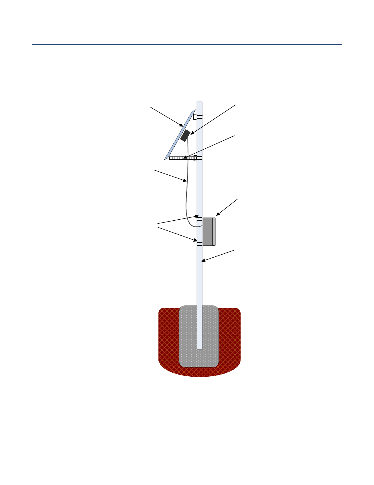
Figure 1 illustrates a typical 12V Solar Power System installation that shows a highlevel description of the system components.
Figure 1: Solar System Architecture
A. Solar Module
(May include 1-4 modules)
G. 2" - 4" Pole System
Support. Not provided by
Ventev
F. Enclosure Mounting
Brackets
(2 PL)
B. Junction Box
D. Adjustable Module
Support Structure
(Tilt angle varies based on
location)
C. Module Interconnect
Cable (Up to 15’ in Length)
E. Enclosure (contains
battery /power and
controller)
Chapter 1 The Ventev Solar Power System Overview
12 Ventev Solar Power Systems
Installation, Operation and Maintenance Guide
The solar system is delivered to the customer site with each of the following major
components.
A. Solar System Controller
The controller is the ‘heart and brains’ of the solar power system. It contains a 4
stage battery charging algorithm for rapid, efficient, and safe battery charging as
shown in Figure 2.
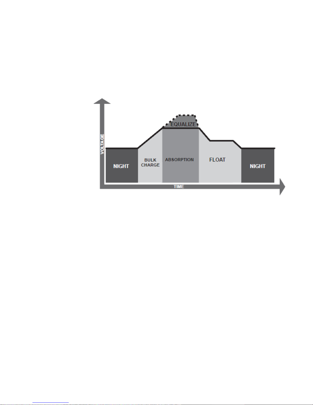
Figure 2: Battery Controller Charging Algorithm
In the bulk charge state, the battery voltage has not yet reached absorption
voltage and 100% of available solar power is used to recharge the battery.
Absorption voltage is the normal, fully charged state. When the battery has
recharged to the absorption voltage setpoint, constant-voltage regulation is used to
prevent heating and excessive battery gassing. After the battery has fully charged
the controller reduces the battery voltage to a float charge (or trickle charge).
Depending on battery history, the battery remains in the absorption stage for 3 or 4
hours before transitioning to the float stage.
Where flooded batteries are used, the controller will equalize the batteries for
three hours every 28 days. Equalize charging raises the battery voltage above the
standard absorption voltage so that the electrolyte gasses, preventing electrolyte
stratification and equalizing the individual battery cell voltages. The controller
also contains a special charging function to attempt to recover batteries that
discharge too low.
The following protections are available and readily observable via LEDs on the
controller faceplate:
1. Solar overload. If the solar current exceeds the maximum solar rating, the
controller will stop charging until the solar current returns to within its
operational rating. Status will be displayed on the faceplate via LEDs.
2. Load Overload. If the load current exceeds the maximum load current rating,
the controller will disconnect the load. The controller will then attempt to
reconnect the load two times approximately 10 seconds apart. If the overload

Document #: 06809 13
remains after these two attempts, operator intervention is required to clear
the fault after normal current is verified. The fault condition will be displayed
on faceplate LEDs until cleared.
3. Solar Module Reverse Polarity. The controller is fully protected against
inadvertent reversal of lead connections. No damage to the controller will
result, but the erroneous connection must be corrected for proper operation.
4. Battery Reverse Polarity. Similarly, the controller will not be damaged if
battery leads are reversed, and again the problem must be resolved for proper
operation.
5. Damaged Local Temperature Sensor. If the local temperature sensor is
damaged, charging stops to avoid over- or under-charging. This critical error
requires vendor support to resolve the failure.
6. Damaged Internal Temperature Sensor. Internal temperature of the controller
is monitored on the controller heat sink. Temperatures above 85 Deg. C can
damage internal controller electronics, so the unit shuts off when the heat sink
exceeds that temperature. When the temperature falls below 80C, the
controller resumes operation.
7. High Voltage Disconnect. If the battery voltage exceeds the controller’s
maximum regulation limit, the solar and load will be disconnected until the
voltage decreases to the high voltage reconnect threshold. LEDs on the
faceplate will display this status.
Load from the system is connected directly to the solar controller. The controller
will disconnect loads when the battery has discharged to a low state of charge and
reconnect system loads when battery capacity returns. Load control is fully
automatic. As the battery discharges, status LEDs on the controller faceplate will
show charge levels. The following general load control notes should be observed:
• 6, 10, and 20 Amp controllers provide load control.
• The controllers have a 15 V maximum voltage limit (30 V @ 24V).
• Load connection is NOT a regulated voltage output. Load terminal
voltage is approximately the same as the battery voltage unless the
controller is in load voltage condition where load is turned off.
• Currents of multiple loads wired in parallel must not exceed the total
current rating of the controller.
B. Solar Module
Solar modules provide the energy source to keep battery(s) charged. The number
of modules needed depends on site specifics, such as geographic location in the
country, site specific needs such as load demand, and available/access to the sun.
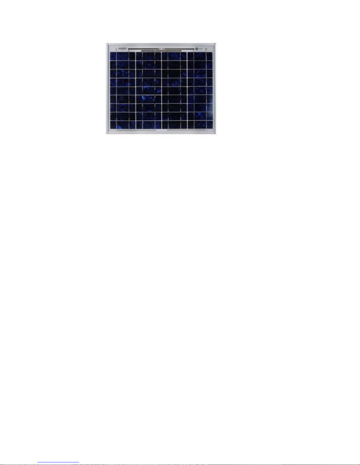
Figure 3 is a photograph of a typical solar module.
Chapter 1 The Ventev Solar Power System Overview
14 Ventev Solar Power Systems
Installation, Operation and Maintenance Guide
Figure 3: 12 Volt, 20 Watt Solar Module (BP Solar SX 3201)
Solar electric modules convert the sun's energy into direct current (DC) electricity.
The systems contain a matrix of high performance monocrystalline or
multicrystalline modules.
The Solar modules are securely attached to the pole with adjustable fasteners to
enable tilt alignment to match the latitude at which the module is installed and
horizontal adjustment for maximum tracking of the sun.
C. Junction Box
The junction box provides a junction to connect the module(s) to the solar
controller through a fused circuit inside the enclosure. Multiple solar modules can
be connected together, either in series or parallel depending on voltage
requirements, and via a single multi-conductor cable connected to the solar
controller.
D. Module Interconnect
The module Interconnect is a multi-conductor cable sized sufficiently to carry the
current to the solar controller from the solar modules. The cable comes
preconfigured with connectors, etc.
E. Adjustable Module Support Structure
The configuration shown in Figure 1 is a single solar module configuration. Support
structures come in varying sizes and configurations to accommodate the types,
number and size of solar modules and pole sizes on which they will be mounted.
Therefore, the customer is required to provide the pole size consistent with the
solar system size (which determines the pole size needed.)
F. Enclosure
The enclosure houses the battery, solar controller, wiring, termination blocks and
fusing for the system. Figure 4 shows a typical enclosure in the configured system
housing two batteries, wiring, and the solar controller.
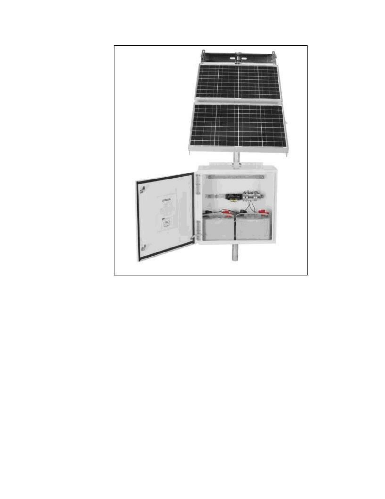
Document #: 06809 15
Figure 4 Typical Enclosure with Solar Module
The enclosures arrive on site pre-wired per the purchaser’s needs, including the
solar controller, terminal blocks, and fuses mounted on DIN rails. The enclosure is
typically sized to accommodate batteries which are staged in the bottom of the
enclosure. Smaller system enclosures are of polycarbonate composition, and the
remaining powder coated aluminium sized to accommodate the batteries required.
Refer to TESSCO.com to review the current solar power enclosure sizes.
G. Enclosure Mounting Brackets
The enclosure mounting kits are used to attach the enclosure to the pole. The
mounting brackets are sized to match the system, and kits provided to fit 2 3/8”
and 4 1/2” OD pipes.
H. Pole System Support
The mounting poles are not part of the solar system package, but can be provided
separately. Sizing will depend on the solar system purchased, including number of
modules needed, enclosure size, etc.
Chapter 1 The Ventev Solar Power System Overview
16 Ventev Solar Power Systems
Installation, Operation and Maintenance Guide
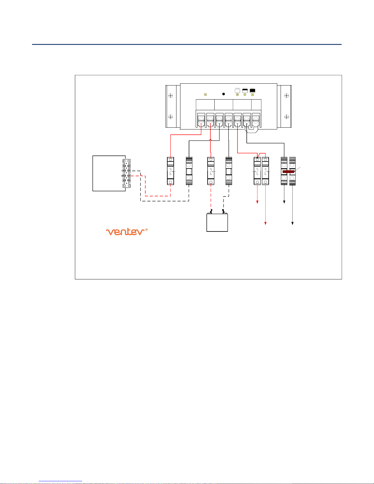
Wiring Diagram
Figure 5 is a copy of the door wiring diagram for the 12 Volt, 10 Watt solar system.
(-) 2
1
(+)3
4
10 Watt
Solar
Module
Fuse Fuse Fuse
+ -
LOAD
#1
W1-R
W2-B
Solar
Fuse
+
-
LOAD
#2
NOTES:
1. All wires 10 AWG unless otherwise specified.
2. Dashed items are connected at customer site.
3. Dotted wires are not provided with wiring kit.
4. Ventev® reserves the right to substitute equipment and/or components
in this system as required.
5. The solar module listed in this diagram may vary as required by
TESSCO Technologies but will be greater than or equal to the
power levels shown.
Battery Load
Load
W3-R
W4-B
W6-R
W7-B
W8-R
+ -
12 Volt
18 Amp/Hr
Battery
W9-R W10-B
Note Terminal Block
Jumper Installed at Factory
VENTEV INNOVATIONS, A DIVISION OF TESSCO TECHNOLOGIES, INC.
10999 McCormick Road
Hunt Valley, MD 21031
EMAIL: Info@ventev.com
TOLL FREE: (800) 759-9996
SOLAR POWER SYSTEM
12VDC, 10W, 18Ahr, -40° TO 60°C
VS01-12-0010-018
(TESSCO SKU 09557)
6.5 AMP SOLAR CONTROLLER
+ - + - + -
REMOVE
JUMPER
WIRE FOR
FLOODED
BATTERY
(
)
(
)
SOLAR
4 3
BATTERY
2 1
LOAD
6 5
SEALED
OR
FLOODED
SELECT
Battery Status
+ -
+ -
+ -
Temp SensorCharge Status
12 Volts
DC
Figure 5: 12 Volt, 10 Watt Solar System Wiring Diagram
With the enclosure delivered to the site pre-wired, solid lines in the diagram
(Figure 5) indicate factory wiring, dashed lines represent wiring provided with the
system but require on-site installation and connection after the solar modules are
mounted and battery(s) installed. Dotted lines indicate wiring not provided in the
package that are to be supplied on-site by the customer.

Document #: 06809 17
Chapter 2 Solar Power System
Installation
This chapter provides detailed instructions to install the 12V Solar Power System
for operation. Topics discussed in this chapter include the following:
• Installation Overview, 18
• Identifying a Site, page 19
• Assembling and Mounting Guidelines, page 24
• Mounting the Battery Enclosure
• System Wiring, page 25
• Wiring and Installing the Battery, page 31
• System Checkout and Commissioning 32
 Loading...