

Ventev TerraWave M6060060O1D41202I Quick Start Manual
2.4/5 GHz 6 dBi Omnidirectional Wi-Fi Light Globe Antenna
with 4 RPSMA Plugs for LED Light Globes
Ventev's TerraWave 2.4/5 GHz 6 dBi Multiple-Input and Multiple-Output (MIMO) Omnidirectional Wi-Fi Antenna for
LED Light Globes transforms outdoor light globes into Wi-Fi hot spots. The antenna is designed to operate with the
most modern 802.11ac access points with RPSMA connectors. This unique antenna installs inside outdoor lighting
globes to ensure concealed, high-performance Wi-Fi. The antenna delivers as a kit with Printed Circuit Board antenna
elements, stand-off spacers, and associated attachment hardware. Installers must integrate the antenna elements
onto the light globe’s heat sinks as described in mounting instructions.
Every Ventev TerraWave antenna is covered by a 2- year TerraNet warranty program. Contact Ventev at 800-851-4965, or
sales@ventev.com for questions and to purchase product.
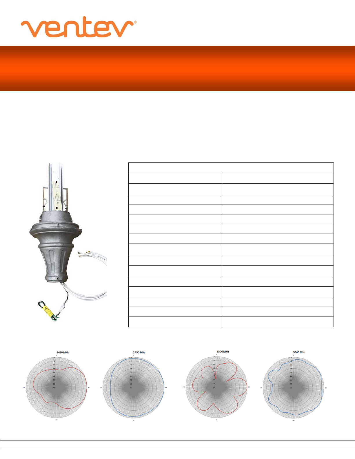
Specications
Model M6060060O1D41202I
Frequency Range 2400 ~ 2500 MHz / 4900 ~ 5850 MHz
Bandwidth 100/ 985 MHz
Gain 6 dBi
Vertical Beamwidth 50° / 30°
Horizontal Beamwidth 360° / 360°
VSWR ≤ 2.0 / ≤ 2.0
Antenna integrated into LED
Light Globe
Nominal Impedance 50 Ohms
Polarization Vertical
Max Power Rating 10 Watts
Dimensions 6” (H) x 4” (W)
Weight 1 lb.
Connector 4 x RPSMA Plug
Number / Length / Type Pigtails 4 x 3’ Pigtails / RG58
Operating Temperature Range -40°F to +158°F
E-Plane Pattern H-Plane Pattern
2.4 G
Hz
www.ventev.com/infra sales@ventev.com 800-851-4965
E-Plane Pattern H-Plane Pattern
5 GHz
2.4/5 GHz 6 dBi Omnidirectional Wi-Fi Light Globe Antenna
with 4 RPSMA Plugs for LED Light Globes
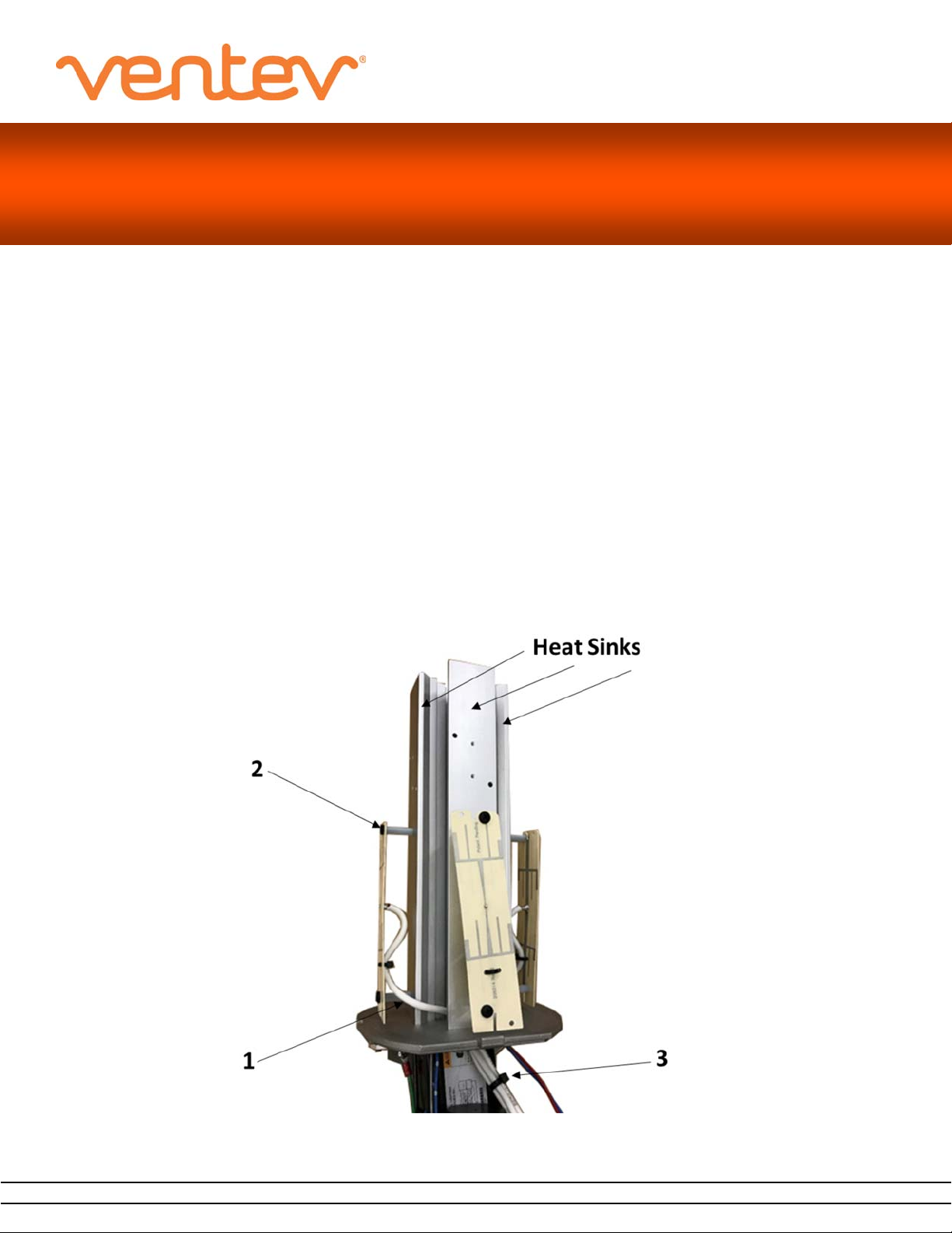
Installation Instructions
Note: These procedures assume the Heat Sinks have been pre-drilled to host the antenna Stand-Os, and the center hole in
the bottom of the cast metal base has been enlarged to t the antenna connectors.
1. Select a Printed Circuit
right side of t
item #1.
2. Using the plastic screws and spacers provided, carefully mount the PCB antennas to the heatsinks. Using caution
not to bend the PCB or
3. Repeat for the remaining 3 PCBs.
4. Dress the cables to rem
exceed a 1” bend radius. Zip-tie the cables to provide strain relief. Refer to Image item #3.
he antenna being installed and down thru the 1.0” diameter hole in the
Board (PCB). Insert the PCB’s cable and connector between the heatsink extrusions to
center plate. Refer to Image
overtighten the plastic screws. Refer to Im
ove any excess slack from above the mounting plate using caution not to kink the cable or
age item #2.
the
www.ventev.com/infra sales@ventev.com 800-851-4965
 Loading...