


Ventcroft Ltd.
Goddard Road,
Astmoor, Runcorn,
Cheshire WA7 1NQ,
Great Britain.
Phone: 01928 581098
Fax: 01928 581099
E-Mail: info@ventcroft.co.uk
http://www.ventcroft.co.uk
Manufacturing Global Security in Great Britain.....with PrideManufacturing Global Security in Great Britain.....with Pride
VI40.1 Created 05/11/2001 Issue 1.3
SPEClFlCATlONS
If you experience any difficulties with this product,
please call our Technical Help-Line
01928 581098
FIRE DETECTION PANEL
Mains Supply Voltage
Transformer Primary Thermal Fuse
Quiescent Current standby
Maximum Overall Current Supply
Maximum Sounder Supply Current
Maximum Zone Output Current
Current Draw - Fault Buzzer On
Current Draw - Fault Buzzer Off
Current Draw - Fire Alarm
Power Supply
Battery Standby
220V dc 50 Hz
o
1A 102 C (Non Replaceable)
48 mA (Buzzer Muted)
1A dc (MAX)
750 mA (0.75A)
50 mA (0.050A)
61 mA (0.61A)
53 mA (0.53A)
95 mA (0.95)
Number of Zones
Detector Voltage Supply
Maximum Current Supply
Monitoring
Maximum Detectors per Zone
Maximum Call Points per Zone
Zone Circuit
FT1BS: 1 Zone
FT2BS: 2 Zones
21 V dc +/- 10%
50 mA dc
Healthy 2mA <> 7.5mA (Nom.)
Fire 17mA <> 41mA (Nom.)
Short Circuit >43mA (Nom.)
Open Circuit <2mA (Nom.)
20 (Low Current Types 30uA)
Unlimited
Switch Voltage Output
Max Current
Outputs
Monitoring
Sounders Outputs
27.2 V dc +/- 10%
750 mA DC (MAX)
2 Independently fused
Open Circuit
Short Circuit
Reversed
Battery Charging Voltage
Monitoring
Battery Input
27.2 V dc (adjustable)
Open Circuit
Short Circuit
Less than 22 V dc
Reversed
F1 - Bell 1
F2 - Bell 2
F3 - Battery
F4- Mains Supply
Mains Thermal Safety Fuse
Fuses
1A Anti Surge 20 mm Glass
1A Anti Surge 20 mm Glass
1A Anti Surge 20 mm Glass
1A Fast Blow Mains 20 mm Ceramic
o
102 C (non replaceable)
Contacts
Maximum Current
Maximum Voltage
Auxiliary Relay
NO, C, NC (Voltage Free)
1A dc/ac
30 V dc
Front Cover
Back Box
Polycarbonate - Fire Retardant
Polycarbonate - Fire Retardant
Housing
Europan
British
Ingression Protection Rating
CE
To conform to BS5839:Part 4 1988
IP20
CE
Compliance
1 Zone
2 Zone
FT1BS
FT2BS
Re-Ordering
Warranty
2 Years from Date of Manufacture
(Date of manufacture can be found marked on the PCB)
FIRETRAXFIRETRAX
TM
Designed to Comply with BS5839 part 4 1988
FT1BS
FT2BS
Page 12
1.0 - Introduction
1.1 - Description Page 3
1.2 - Features Page 3
1.3 - Box Contents Page 3
2.0 - Connections
2.1 - Terminal Diagrams Page 4
2.2 - Field Connections Page 4
2.3 - Key Switch Page 4
2.4 - A/C Input Page 4
2.5 - Internal Buzzer Page 4
3.0 - Operating Controls / Indicators
3.1 - Keys Switch Page 5
3.2 - Control Buttons Page 5
3.3 - Internal Buzzer Page 5
3.4 - Front Panel Indicators Page 6
3.5 - Internal PCB Mounted LED Indicators Page 6
4.0 - Guide to Planning a fire alarm system
4.1 - Introduction Page 6
4.2 - Install Planning Page 7
4.3 - System Types - Levels of Protection Page 7
4.4 - General Information Page 7
4.5 - Detection Devices Page 7
4.6 - Automatic Point Detectors Page 8
4.7 - Manual Call Points Page 8
4.8 - Remote Indicator Modules Page 8
4.9 - Auxiliary Relay Page 8
4.10 - Sounders Page 8
4.11 - Remote Ring Page 9
5.0 - Installation and Wiring Guide
5.1 - Mounting the Control Indicator Equipment (CIE) Page 9
5.2 - Pre-Installation Testing Page 9
5.3 - Mains Connection Page 9
5.4 - Installing The Battery Page 10
5.5 - Adjusting the Battery Charge Voltage Page 10
5.6 - Automatic Detection Devices and Manual Call Points Page 10
5.7 - End of Line Resistance Monitoring Page 10
5.8 - Page 10
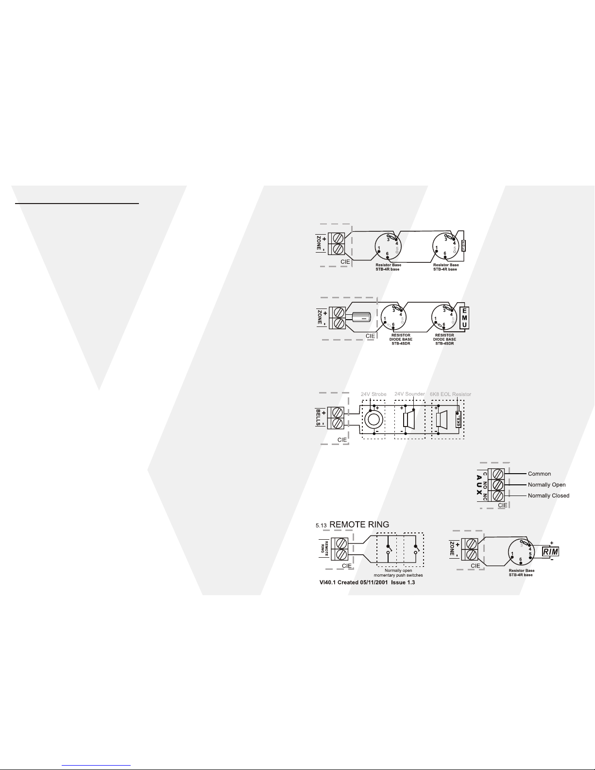
5.9 - Practical Wiring of Resistor Bases Page 11
5.10 - Practical Wiring of Diode Resistor Bases Page 11
5.11 - Sounders Page 11
5.12 - Auxiliary Relay Wiring Page 11
5.13 - Remote Ring Page 11
5.14 - Remote Indicator Module Page 11
6.0 - Specifications Page 12
7.0 - Commissioning Certificate / User Systems Details
7.1 - Certificate of Installation / Commissioning Page B1
7.2 - Commissioning and Maintenance Record Page B2
7.3 - Event Log Page B3
7.4 - User Operating Instructions Page B4
End of Line Electronic Monitoring Unit
Table of Contents
Page 2 Page 11
5.11 SOUNDERS
2
All sounder wiring should be in fire retardant type cables. 1mm or greater copper cables should
be used to avoid minimum volt drop. Its may be necessary on long cable runs to use greater cable
sizes, there should be no spurring or "T offs" from the main run.
5.9 PRACTICAL WIRING OF RESISTOR BASES
FOR RESISTOR END OF LINE MONITORING
Diode bases should never be used when using EOL resistor monitoring
5.10 PRACTICAL WIRING OF DIODE RESISTOR
BASES FOR EMU END OF LINE MONITORING
5.14 REMOTE INDICATOR MODULE
5.12 AUXILIARY RELAY WIRING
The Auxiliary relay should be considered as a low
current switch, and should not be connected
directly to magnetic door holders and should only
be used to switch a larger switching relay.

Page 10
Page 3
1.1 DESCRIPTION
The Ventcroft FIRETRAX (FT2BS & FT1BS) are both fire control panels designed to comply with
BS5839:Part 4 1988 used in systems in the detection of fire, described in this manual as
CIE(Control Indicator Equipment). The CIE has 1 or 2 fire detection circuits(model dependent) for
the connection of fire detection and call point devices. The CIE is powered from the mains supply
and utilizes a backup circuit to allow the connection of stand-by batteries allowing the CIE to
function with a mains failure.
In the event of fire detection two sounder outputs are provided to drive 24V sounder or strobe units
to communicate evacuation, the sounder output can also be remotely triggered via the remote ring
input. A relay provides a switchable voltage free output which changes state during a fire activation
and can be utilized, for example to switch devices such as digital phone communicators or to
indirectly release power to fire door holding devices.
1.0 INTRODUCTION
1.2 FEATURES
! MAINS POWER LED
! ZONE FIRE ALARM LED'S
! FACE MOUNTED CONTROL BUTTONS
! ZONE FAULT LED'S
! GENERAL FAULT LED'S
! TWO FUSED SOUNDER OUTPUTS
! FUSED BATTERY INPUT
! KEY SWITCH ENABLE
! MICROPROCESSOR CONTROLLED
! INTERNAL SYSTEM FAULT LED'S
! POLYCARBONATE HOUSING
! ACTIVE END OF LINE OPTION
! END OF LINE RESISTOR MONITORING
! CLASS CHANGE FACILITY
! DOUBLE POLE AUXILIARY RELAY
! 1 AMP TOTAL POWER SUPPLY
! INTERNAL SPACE FOR UP TO 2 x 2.1 Ah 12 V BATTERIES
! COMPLIES WITH B.S. 5839 PART 4 1988
! UP TO 20 AUTOMATIC DETECTION DEVICES PER ZONE
! UNLIMITED NUMBER OF CALL POINTS PER ZONE
! CE
5.6 INSTALLING MANUAL CALL POINTS AND
AUTOMATIC DETECTION DEVICES
Manual Call Points must be installed before automated detection devices as
shown below in (fig. 5.7), when using End of Line resistor monitoring. In the very last device a 6K8
ohm resistor must be placed across the device to provide end of line monitoring. In all detection
devices automatic or manual a 470 ohm resistor should be connected in series with its terminals
which are presented to the CIE.
In some installations it may not be convenient for all call points to be installed before the
automated detection devices , in these cases an EMU (Electronic Monitoring Module) provides
active end of line monitoring and allows the different types of detection devices to be mixed in any
order. The EMU device must be placed in the furthest most detector. When using an EMU a
capacitor must be placed across the zone terminals in the CIE. Shown in fig 5.8
2
Devices should be wired in 1mm or greater copper cable, should be no spurring or "T offs"
from the main run.
there
1.3 Box Contents
1x FIRETRAX FT1BS OR FT2BS - Fire CIE Panel
1x Instructions VI40.1
1x User Insert VI41.1 for Instructions VI40.1
1x Accessory Bag Including
2x 816 Keys
2x Self Tapping Screws - For Fixing Front Cover to the Base
1x Purple Fast-on to Fast-on Lead
1x Black Fast-on to Tinned End Lead
1x Red Fast-on to Tinned End Lead
2x Spare 1A 20mm Glass Fuses
2x 6K8 Resistors
5.7 USING EOL (End of Line) RESISTOR MONITORING
Resistor basses must be used, diode resistor bases must never be used as fault will not be reported.
5.8 USING EOL ELECTRONIC MONITORING UNIT
When using electronic monitoring devices it may be necessary to fit a capacitor in the CIE, correct polarity
must be observed when connecting the capacitor. Diode resistor basses must be used, shown below
VI40.1 Created 05/11/2001 Issue 1.3
5.5 ADJUSTING THE BATTERY CHARGING VOLTAGE
On completion of the installation and during regular maintenance the battery
charging voltage should be 27.2 V dc, measured at the battery input terminals on
TB3 14 & 15 while not connected to the battery. The battery charging voltage may
be set by adjusting potentiometer VR1 whilst measuring across the battery
terminals 14 & 15 on TB3. Access to VR1 is gained from the rear of the PCB.
5.4 INSTALLING THE BA TTERY
Install the 24 V battery normally made of 2x12 V SLA
batteries connected in series. Correct polarity connection
must be observed. The pre installed 6K8 resistor must be
removed before connecting the batteries.

Page 4
5.0 INSTALLATION AND WIRING GUIDE
5.1 MOUNTING THE CIE EQUIPMENT
Identify a suitable location for mounting the CIE (Control Indicator Equipment) taking into
consideration the routing of cables and access to the CIE for both installation and user. Remove
the PCB and keep safe, mark the location of the holes to be drilled by offering the CIE rear
enclosure to the wall. Drill holes for suitable rawl plugs to provide a strong and secure installation.
2.0 CONNECTIONS
2.1 Terminal Diagrams
2.2 FIELD CONNECTIONS - TB3
These terminals provide the outputs to drive the internal and external sounders and strobes.
There are two separately fused outputs, both circuits are monitored for open and short
circuits conditions with EOL monitoring resistors (6K8). Sounders must be polarised, fully
suppressed and designed for 24VDC operation. The total load for both circuits must not
exceed 750mA. If the sounders or strobes are not polarized a fault will be indicated. The
same wiring rules apply as for the detector circuits.
+
BELL 1
-
+
BELL 2
-
REMOTE
RING
The REMOTE RING terminals can be used to force trigger the bell relay without a fire
condition occurring or operating the auxiliary relay. This gives the ability to wire remote
evacuation switches. This is NOT a latching trigger and will return to a normal state when the
connection is broken. Often used as a class change.
C
NO
NC
AUX
The CIE is fitted with a double pole auxiliary 1 Amp relay which operates only when a fire
condition is recognised. The relay does not operate if the manual SOUND ALARM is pressed.
+
BATT
-
These terminals provide connection for a 24V backup battery. 12V batteries are connected in
series. The 6K8 Ohm resistor must be removed before fitting any battery to this terminal.
Failure to remove the resistor will not enable the panel to test the batteries health.
2.3 KEY SWITCH - TB2
KEYSW
These terminals provide the connection for the on board key switch which enables and
disables the control buttons. When the switch is closed the control buttons are enabled. No
other connection should be made to these terminals.
2.4 A/C SUPPLY INPUT - TB1
A/C
These terminals provide the connection from the on board transformer, which provides
approximately 32 V ac. No other connection should be made to these terminals
2.5 INTERNAL BUZZER - TB4
BUZZER
These terminals provide the connections to supply a wired internal buzzer. These terminals
are only fitted when the on board buzzer SND1 is not fitted. No other connection should be
made to these terminals.
+
ZONE 2
-
+
ZONE 1
-
These terminals provide the inputs allowing the connection of smoke heads and alarms
points to the CIE. All devices must be connected in parallel to the CIE. 22V DC is supplied to
the zone terminals suppling a maximum current of 50 mA per zone, a 6K8 Ohm end of line
resistor must be fitted in the further most detection device from the CIE. To produce a fire
state the detector should draw sufficient current to trigger a fire alarm and have a 470 Ohm
resistor in series. Not only do the terminals detect a fire state but they offer detection of open
and short circuit of the cables.
FIRETRAX CIE PANEL
4.11 REMOTE RING
The connection of a normally open switch to the remote ring terminals, will allow the external sounders to be
used for ancillary functions for example 'Class Change.' Multiple switches can be used by connecting the
switches in parallel.
This work must be carried out by a suitably qualified engineer and installed to the latest mandatory
Fire Alarm Installation Regulations which are applicable at the time of installation. The correct
polarity must be observed and a good earth must be used.
The Fire Alarm system must not share its mains supply with any other electrical circuit and should
be connected via an isolating protective device and labelled 'FIRE ALARM DO NOT SWITCH
OFF.'
Wire To Mains
Power Supply
5.3 MAINS CONNECTION
T erminate the mains connection using suitable earthed mains cable to a fused supply, ensuring all
power is isolated before attempting to terminate and wires. This supply should not be shared with
any other appliances.
5.2 PRE-INSTALLATION TESTING
It is STRONGLY recommended that the panel is powered up and tested prior to the external
system circuits being connected.
• Make sure the external system wiring has been tested and the results recorded.
• Connect the batteries together (see FIG 5.4, page 10) and connect the + & - 'spade terminals'
to the PCB terminal block. Ignore the fault indication at this stage.
• Connect the mains supply (see FIG 5.3, page 9). The fault indication will be removed
• In turn, temporally disconnect each of the monitoring resistors from the terminals, check for
a fault indication, and reconnect for the fault to reset.
• In turn, use a 470 ohm resistor to temporally connect across the detector circuit terminals
to create a FIRE condition. Reset as per the Operating Instructions.
Once the panel has been tested and the operating procedure is understood, the external
connections can be made, ONE CIRCUIT AT A TIME.
Page 9
VI40.1 Created 05/11/2001 Issue 1.3

Page 5
Page 8
3.1 KEYSWITCH
The Keyswitch is used to enable or disable the three control buttons. SOUND ALARM,
MUTE and RESET . The key can only be removed in the control disabled position, with
the key inserted and turned clockwise the controls are enabled.
3.0 OPERATING CONTROLS
The key switch and three buttons on the front of the CIE allows the user and engineer to
access the CIE different operation functions.
The sounder mute push button is used to silence the system sounders and
the internal buzzer during a fault condition. When the mute button is pressed
during a fire activation the system sounders will be silenced but the internal
buzzer will sound continuously until the reset button is pressed. The mute
button is also used to silence the system sounders when the SOUND
ALARM button has been pressed. If the mute button is pressed during fault
condition the internal buzzer will cease to sound continuously and will only
bleep once every 5 seconds. Labelled on the PCB as S2 Mute.
MUTE
The reset button is used to reset and initialize the CIE after a fire activation or
from powering up. After a fire activation before the reset button can be
pressed the mute button must first be pressed, otherwise no reset will take
place. If reset button is pressed with or without a fault condition present the
CIE will re-initialize, illuminating all external LED's along with sounding the
internal buzzer for 3 seconds. The auxiliary supply to the zone terminals is
removed during the initialization period, resetting any smoke heads
connected to the zone inputs. Labelled on the PCB as S3 RESET .
RESET
The SOUND ALARM button is used to activate the sounder circuits, and can
be used to evacuate the building, resound or test the sounders. Labelled on
the PCB as S1 EVAC.
SOUND
ALARM
3.2 CONTROL BUTTONS
A constant tone from the buzzer will indicate either :
1. General Fault
2. Muted Fire Alarm
A rapid on / off tone indicates a fire activation
3.3 INTERNAL BUZZER
Constant
Fast Beep
4.7 MANUAL CALL POINTS
Call points should be sited with the following considerations, the rules below are mandatory.
1, On all escape routes.
2, On landings of stairways.
3, Near final exits to the open air.
4, Nobody has to travel 30 metres to reach a call point.
5, Call Points must be 1.4 metres above the floor and be free from obstruction.
4.10 SOUNDERS
Sufficient sounders should be installed so as to ensure alarm audibility in all areas of the building /
location ensuring a fast and full evacuation. Two sounder outputs are provided on the CIE (Control
Indicator Equipment) allowing the connection of two independent sounder circuits, see BS 5839
Part1:1988 section 9.4 for detailed information.
1. Sufficient sounders should be installed to ensure sufficient dB levels around the premises
to aid a complete evacuation, even in the event of a failure of one of the sounder circuits.
75dB should be provided at the bed head of a sleeping person (With al doors closed). 65 dB
should be provided in all other working areas or 5 dB above any noise the re-occur for more
that 30 seconds.
2. The minimum sound levels must be produced in all parts of the building / location. This
includes restricted area's that are infrequently visited, such as service ducts, store rooms,
toilets or lift shaft motor rooms etc.
3. All sounders in a building should be of similar type, do not mix electronic sounders with bells.
4.6 AUTOMATIC 'POINT' DETECTORS
There are four common types of automatic 'point' detectors installed to aid the detection of fires
within a residential / commercial building. Ionisation and Photoelectronic Devices detect the
products of combustion (smoke). Rate of Rise and fixed Temperature Devices detect changes
in temperature (heat). Optical smoke Devices are used for, slow burning smouldering fires, ie for
escape routes and corridors, wood or cardboard stores, do not use in steamy, dusty or smoky
areas such as kitchens and bathrooms etc. Ionisation Smoke Devices are used for fast burning,
high energy fires, ie for petrochemical or solvent stores, electrical switch rooms. Heat Devices
are used when the environment is subject to constant levels of smoke or dirt, ie loading bays,
boiler rooms, kitchens, laundries and plant rooms. Fixed Temperature Heat Devices are used
where high ambient temperatures exist, or in areas where sudden changes in temperature may
occur, ie near large windows or heat producing processes. Rate of Rise Devices have fixed
temperature operation, but also looks for sudden rises in temperature giving faster reaction than
standard fixed temperature detector. Sufficient detection devices should be installed to provide
adequate protection coverage.
4.8 REMOTE INDICAT OR MODULE
Remote Indicator Modules can be used to remotely indicate the state of an automatic detection
device. i.e. there may be 10 rooms on a single corridor, if a single detection device were to alarm
each room would haft to be inspected, which would take valuable time. A remote indicator module
can be placed outside each room to quickly guide a correct response.
4.9 AUXILIARY RELAY
The Auxiliary relay terminals can be used as a voltage free interface between the FIRETRAX
FT1BS / FT2BS CIE. T o such devices as magnetic fire door holding devices and communicating
devices to be connected to a phone line. The Auxiliary relay should be considered as a low
current switch, and should not be connected directly to magnetic door holders and should only be
used to switch a larger switching relay.
VI40.1 Created 05/11/2001 Issue 1.3
 Loading...