

VENTCROFT FIRETRAX FT2BS, FIRETRAX FT1BS User Manual

Ventcroft Ltd.
Goddard Road,
Astmoor, Runcorn,
Cheshire WA7 1NQ,
Great Britain.
Phone: 01928 581098
Fax: 01928 581099
E-Mail: info@ventcroft.co.uk
http://www.ventcroft.co.uk
Manufacturing Global Security in Great Britain.....with PrideManufacturing Global Security in Great Britain.....with Pride
VI40.1 Created 05/11/2001 Issue 1.3
SPEClFlCATlONS
If you experience any difficulties with this product,
please call our Technical Help-Line
01928 581098
FIRE DETECTION PANEL
Mains Supply Voltage
Transformer Primary Thermal Fuse
Quiescent Current standby
Maximum Overall Current Supply
Maximum Sounder Supply Current
Maximum Zone Output Current
Current Draw - Fault Buzzer On
Current Draw - Fault Buzzer Off
Current Draw - Fire Alarm
Power Supply
Battery Standby
220V dc 50 Hz
o
1A 102 C (Non Replaceable)
48 mA (Buzzer Muted)
1A dc (MAX)
750 mA (0.75A)
50 mA (0.050A)
61 mA (0.61A)
53 mA (0.53A)
95 mA (0.95)
Number of Zones
Detector Voltage Supply
Maximum Current Supply
Monitoring
Maximum Detectors per Zone
Maximum Call Points per Zone
Zone Circuit
FT1BS: 1 Zone
FT2BS: 2 Zones
21 V dc +/- 10%
50 mA dc
Healthy 2mA <> 7.5mA (Nom.)
Fire 17mA <> 41mA (Nom.)
Short Circuit >43mA (Nom.)
Open Circuit <2mA (Nom.)
20 (Low Current Types 30uA)
Unlimited
Switch Voltage Output
Max Current
Outputs
Monitoring
Sounders Outputs
27.2 V dc +/- 10%
750 mA DC (MAX)
2 Independently fused
Open Circuit
Short Circuit
Reversed
Battery Charging Voltage
Monitoring
Battery Input
27.2 V dc (adjustable)
Open Circuit
Short Circuit
Less than 22 V dc
Reversed
F1 - Bell 1
F2 - Bell 2
F3 - Battery
F4- Mains Supply
Mains Thermal Safety Fuse
Fuses
1A Anti Surge 20 mm Glass
1A Anti Surge 20 mm Glass
1A Anti Surge 20 mm Glass
1A Fast Blow Mains 20 mm Ceramic
o
102 C (non replaceable)
Contacts
Maximum Current
Maximum Voltage
Auxiliary Relay
NO, C, NC (Voltage Free)
1A dc/ac
30 V dc
Front Cover
Back Box
Polycarbonate - Fire Retardant
Polycarbonate - Fire Retardant
Housing
Europan
British
Ingression Protection Rating
CE
To conform to BS5839:Part 4 1988
IP20
CE
Compliance
1 Zone
2 Zone
FT1BS
FT2BS
Re-Ordering
Warranty
2 Years from Date of Manufacture
(Date of manufacture can be found marked on the PCB)
FIRETRAXFIRETRAX
TM
Designed to Comply with BS5839 part 4 1988
FT1BS
FT2BS
Page 12
1.0 - Introduction
1.1 - Description Page 3
1.2 - Features Page 3
1.3 - Box Contents Page 3
2.0 - Connections
2.1 - Terminal Diagrams Page 4
2.2 - Field Connections Page 4
2.3 - Key Switch Page 4
2.4 - A/C Input Page 4
2.5 - Internal Buzzer Page 4
3.0 - Operating Controls / Indicators
3.1 - Keys Switch Page 5
3.2 - Control Buttons Page 5
3.3 - Internal Buzzer Page 5
3.4 - Front Panel Indicators Page 6
3.5 - Internal PCB Mounted LED Indicators Page 6
4.0 - Guide to Planning a fire alarm system
4.1 - Introduction Page 6
4.2 - Install Planning Page 7
4.3 - System Types - Levels of Protection Page 7
4.4 - General Information Page 7
4.5 - Detection Devices Page 7
4.6 - Automatic Point Detectors Page 8
4.7 - Manual Call Points Page 8
4.8 - Remote Indicator Modules Page 8
4.9 - Auxiliary Relay Page 8
4.10 - Sounders Page 8
4.11 - Remote Ring Page 9
5.0 - Installation and Wiring Guide
5.1 - Mounting the Control Indicator Equipment (CIE) Page 9
5.2 - Pre-Installation Testing Page 9
5.3 - Mains Connection Page 9
5.4 - Installing The Battery Page 10
5.5 - Adjusting the Battery Charge Voltage Page 10
5.6 - Automatic Detection Devices and Manual Call Points Page 10
5.7 - End of Line Resistance Monitoring Page 10
5.8 - Page 10
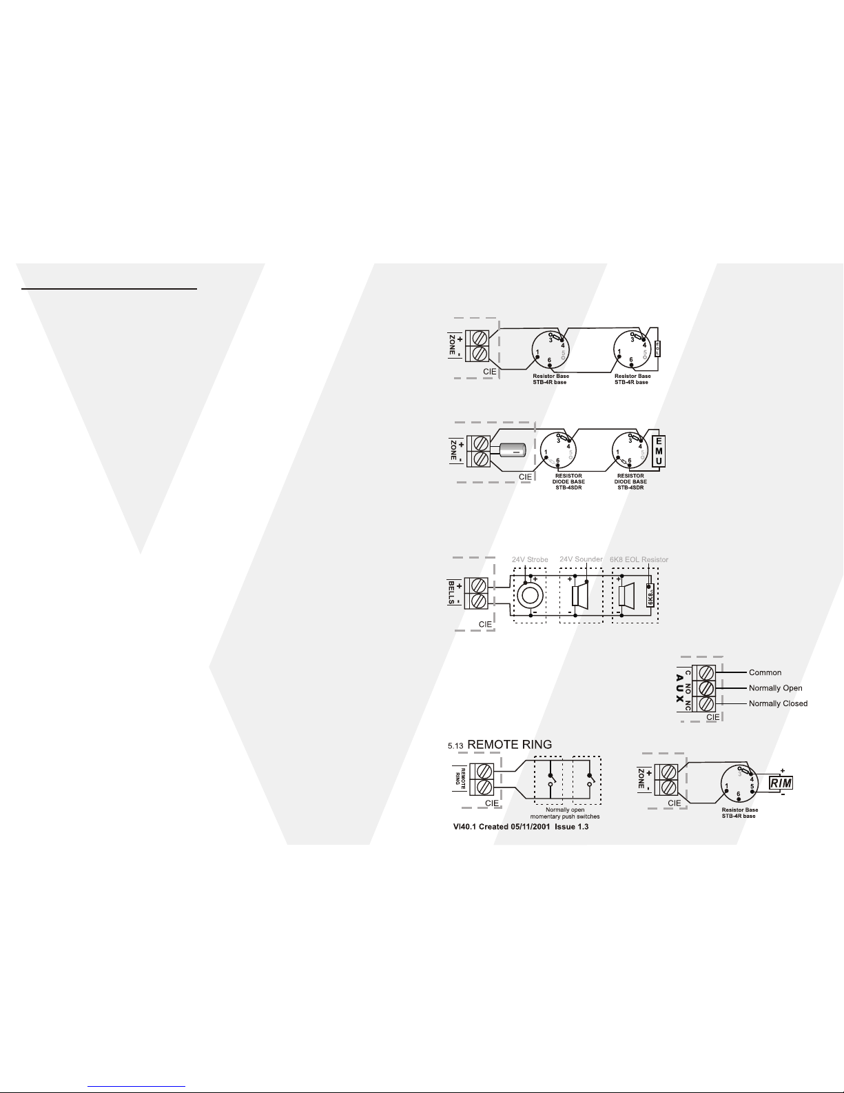
5.9 - Practical Wiring of Resistor Bases Page 11
5.10 - Practical Wiring of Diode Resistor Bases Page 11
5.11 - Sounders Page 11
5.12 - Auxiliary Relay Wiring Page 11
5.13 - Remote Ring Page 11
5.14 - Remote Indicator Module Page 11
6.0 - Specifications Page 12
7.0 - Commissioning Certificate / User Systems Details
7.1 - Certificate of Installation / Commissioning Page B1
7.2 - Commissioning and Maintenance Record Page B2
7.3 - Event Log Page B3
7.4 - User Operating Instructions Page B4
End of Line Electronic Monitoring Unit
Table of Contents
Page 2 Page 11
5.11 SOUNDERS
2
All sounder wiring should be in fire retardant type cables. 1mm or greater copper cables should
be used to avoid minimum volt drop. Its may be necessary on long cable runs to use greater cable
sizes, there should be no spurring or "T offs" from the main run.
5.9 PRACTICAL WIRING OF RESISTOR BASES
FOR RESISTOR END OF LINE MONITORING
Diode bases should never be used when using EOL resistor monitoring
5.10 PRACTICAL WIRING OF DIODE RESISTOR
BASES FOR EMU END OF LINE MONITORING
5.14 REMOTE INDICATOR MODULE
5.12 AUXILIARY RELAY WIRING
The Auxiliary relay should be considered as a low
current switch, and should not be connected
directly to magnetic door holders and should only
be used to switch a larger switching relay.
 Loading...