

2.5A Electronic
Single phase speed controller
Installation and Wiring Instructions
PLEASE READ INSTRUCTIONS IN CONJUNCTION WITH ILLUSTRATIONS.
PLEASE SAVE THESE INSTRUCTIONS.
Stock Ref. N°
W103 03 102M

Fitting & Wiring Instructions 2.5A Single Phase speed Controller
IMPORTANT
PLEASE READ ALL INSTRUCTIONS CAREFULLY BEFORE COMMENCING INSTALLATION
1. It is recommended that this controller is installed by a qualified electrician.
2. The installation and wiring must comply with current IEE Regulations, BS7671, or the
appropriate standards in your country.
3. This controller is not suitable for use in rooms containing a fixed bath or shower.
4. This equipment MUST be earthed
On receipt of your controller, check that:
a). It is the correct rating for the size of
motor
b). the voltage and frequency are correct.
Location
The controller may be sited in any
convenient position that is unaffected by
direct heat sources such as radiators,
boilers, etc. Do not site the controller
where it may be subject to water spray,
condensation, damp or wet conditions.
Ensure the controller is installed in a
ventilated area. Ensure that the
enclosure is securely mounted using
appropriate fixing screws or bolts.
Fitting
Unscrew the two screws and remove the
lid/switch from the mounting box. The
mounting box may be fixed to most
single or double gang recessed metal
outlet boxes or alternatively fixed direct
to the wall for surface cable entry. When
using surface wiring that is not being
contained in conduit, the supply and
output cables must be securely clipped to
the mounting surface, close to the
controller.
Wiring
WARNING: THIS APPLIANCE MUST
BE EARTHED
Ensure that mains supply is isolated
before proceeding with the wiring. The
installation must be provided with a
double-pole isolator switch, having a
contact separation of not less than 3mm,
and be protected with a 3 amp fuse
(U.K).
If using automatic control via electromechanical ON/OFF switched sensor e.g
electro-mechanical thermostat, timer,
relay etc. ensure sensor switch is
adequately rated for the switched load.
After making wiring connections, check
that they are all correct and secure,
replace lid.
NOTES ON RUNNING
Before switching on CHECK:
Control unit and motor/fan are secure
Earth connections have been made and
are secure
Switch on mains
Slide control to maximum and down to
minimum to ensure motor/fan operates
accordingly.
MINIMUM SPEED
The control unit has been factory set to
Vent-Axia’s recommended minimum
speed.
A minimum speed adjuster is located on
the front of the controller and is exposed
when the bottom slide bar is moved fully
to the left. This adjuster is used to vary
the lowest speed setting if the fan does
not revolve when the controller is set to
minimum speed.
Using a small screwdriver, turn the
adjuster clockwise to increase the
minimum speed setting.
After any adjustment, make sure the fan
will start from a stationary condition by
using the ON/OFF switch with the
variable speed slide knob set6 fully to the
left (minimum speed).
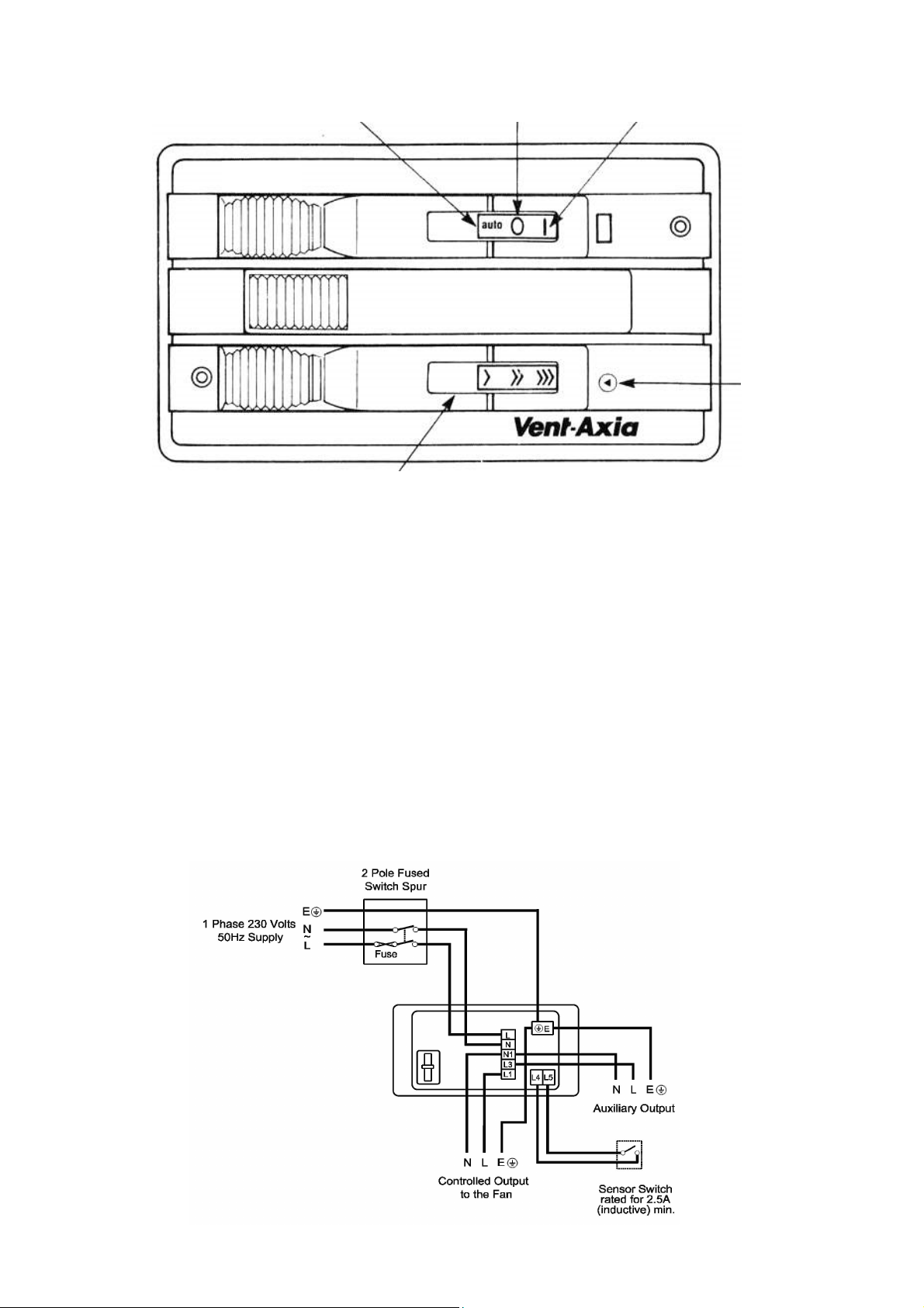
*Automatic
Fan
Fan
MIN. SPEED
ADJUSTMENT
VARIABLE FAN SPEED
*For AUTOMATIC REMOTE SWITCHING (If required)
See also relevant sensor wiring instructions.
Note:
Only mechanical or electro-mechanical switched sensors should be used, rated at 2.5A
inductive 220-240V AC.
Connect sensor switch leads to L4 and L5 in the terminal block.
When slide switch is in the position marked auto automatic switching from sensor/switch
(if fitted) will be obtained. Ensure sensor switch is adequately rated for the full switched
fan load.
For Shutter mechanism (if required) see also relevant shutter wiring instructions.
Note:- Connect the shutter cable to L3 when required. (Note: The load on L3 should be
kept to less than 0.25A (60W) we recommend the use of Vent-Axia 4 core cable when
shutter application is required.
Applicable only to products installed and used in the United Kingdom. For details of
guarantee outside the United Kingdom contact your local supplier.
Vent-Axia guarantees its products for two years from date of purchase against faulty material
or workmanship. In the event of any part being found to be defective, the product will be
repaired, or at the Company’s option replaced, without charge, provided that the product:-
Has been installed and used in accordance with the instructions given with each unit.
Has not been connected to an unsuitable electricity supply. (The correct electricity
supply voltage is shown on the product rating label attached to the unit).
Has not been subjected to misuse, neglect or damage.
Has not been modified or repaired by any person not authorised by the company.
Please return the complete product, carriage paid to your original supplier or nearest Vent-
Axia Centre, by post or personal visit. Please ensure that it is adequately packed and
accompanied by a letter clearly marked “Guarantee Claim” stating the nature of the fault and
The guarantee is offered to you as an extra benefit, and does not effect your legal rights
The Guarantee
IF CLAIMING UNDER TERMS OF GUARANTEE
providing evidence of date and source of purchase.
Head Office: Fleming Way, Crawley, West Sussex, RH10 9YX.
EU Authorised Representative:
Vent-Axia Bedrijvenweg 17 7442 CX Nijverdal Nederland authorisedrep@vent-axia.nl
UK NATIONAL CALL CENTRE, Newton Road, Crawley, West Sussex, RH10 9JA
SALES ENQUIRIES: Tel: 0344 8560590 Fax: 01293 565169
TECHNICAL SUPPORT: Tel: 0344 8560594 Fax: 01293 539209
Web:-www.vent-axia.com Email:- info@vent-axia.com
As part of the policy of continuous product improvement Vent-Axia reserves the right to alter specifications without notice.
462233 M 0921
 Loading...