

Page 1
OPERATION AND
MAINTENANCE
INSTRUCTIONS
SINGLE PHASE
TRANSFORMER
SPEED CONTROLLERS
IMPORTANT – PLEASE READ THESE INSTRUCTIONS FULLY
BEFORE COMMENCING INSTALLATION.
These instructions refer to the following models:
RTRE20: 230 V a. c. 50Hz Maximum Operating Current: 2.0A (max line fuse 4A)
RTRE35: 230 V a. c. 50Hz Maximum Operating Current: 3.5A (max line fuse 4A)
RTRE60: 230 V a. c. 50Hz Maximum Operating Current: 6.0A (max line fuse 8A)
RTRE75: 230 V a. c. 50Hz Maximum Operating Current: 7.5A (max line fuse 8A)
RTRE90: 230 V a. c. 50Hz Maximum Operating Current: 9.0A (max line fuse 16A)
• SAFETY
All electrical installation must be undertaken by a suitably qualified and competent person and must be
carried out in accordance with all relevant Statutory Requirements. Please check the details on the
unit rating plate to ensure that the correct power supply (Voltage, Frequency and Phase) is available.
Do not use the speed controllers with an incorrect power supply, overheating and failure of the circuit
board will occur.
The controller must not be used when the ambient air temperature may exceed 40ºC and where it is
liable to be subjected to water spray.
• INSTALLATION
The controller is suitable for surface mounting only. Remove front cover and ensure backbox is
securely fixed to wall in a well-ventilated area. Route supply and load cables through `Knock-out`
holes provided. If the controller is mounted on a conductive (metal) surface, that surface must be
earthed.
• GENERAL WIRING
Warning: The Control Equipment Must Be Isolated From The Power Supply During Installation
And / Or Maintenance. The Equipment Must Be Earthed.
Connect the power supply from the local isolator (via any appropriate controls if fitted) and the load
supply to the backbox via an appropriate cable gland. Refer to the wiring diagram and select the
appropriate connections for the controller and / or other devices as being installed. Ensure that all
earth connections have been made.
After completing and checking the connections to the controller replace the front cover ensuring that it
is correctly seated in place. Ensure that all cable gland / grommet fixings and lid fixings are tightened
correctly to prevent water ingress.
Transformers within these controllers are not short circuit proof and the necessary short circuit and
overload protection must be provided.
R-TBL01_03-GB 0624 Part. No. 00163610
Page 1 / 5
Page 2
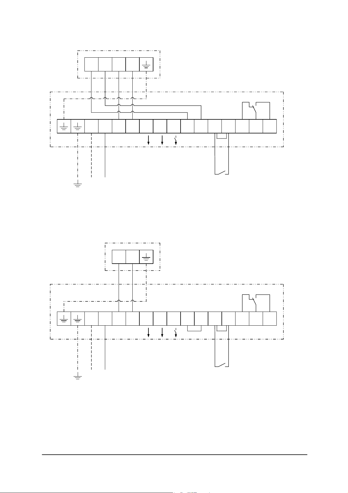
WIRING DETAILS
MOTOR WITH EXTERNAL THERMAL CONTACTS
230V 1PH 50Hz SUPPLY
U1 U2TKTK
N L U1 U2
1 2 3 4 5 6 7 12 1411
N
contact rating
max. 230V/1A
NL
WIRING DETAILS
MOTOR WITHOUT EXTERNAL THERMAL CONTACTS
230V 1PH 50Hz SUPPLY
Fan
L L
(1)
RTRE20…
RTRE75
(2)
contact rating
max. 250V/2A
ROOM
THERMOSTAT
Fan
(1)
(3)
(2)
contact rating
max. 250V/2A
ROOM
THERMOSTAT
N L
NL
L N
U1 U2
1 2 3 4 5 6 7 12 1411
N L L
contact rating
max. 230V/1A
(1) Fan terminals may vary with model. Refer to instructions with the fan for correct terminations.
(2) If room thermostat is not used, fit link between 6-7.
(3) For fans without external thermal contacts fit link between 4-5. Other form of motor protection MUST be used.
RTRE20…
RTRE75
SR149K04
18.06.2004
ALL WIRING MUST BE INSTALLED BY A SUITABLY QUALIFIED AND COMPETENT PERSON IN ACCORDANCE WITH
CURRENT REGULATIONS!
R-TBL01_03-GB 0624 Part. No. 00163610
Page 2 / 5
Page 3
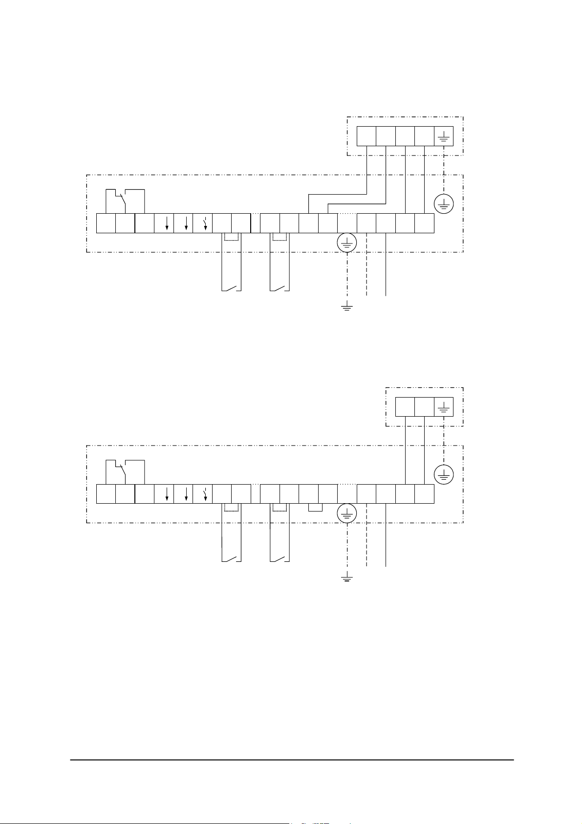
WIRING DETAILS
MOTOR WITH EXTERNAL THERMAL CONTACTS
230V 1PH 50Hz SUPPLY
(2)
contact rating
max. 250V/2A
contact rating
max. 230V/1A
ROOM
THERMOSTAT
WIRING DETAILS
MOTOR WITHOUT EXTERNAL THERMAL CONTACTS
230V 1PH 50Hz SUPPLY
(2)
ANTI FREEZE
THERMOSTAT
N L U1 U211 1412 TK TKRT L L N RT FS FS
NL
U1 U2TKTK
L N
(1)
Fan
RTRE90
(1)
Fan
N L U1 U211 1412 TK TKRT L L N RT FS FS
contact rating
max. 250V/2A
(2)
contact rating
max. 230V/1A
ROOM
THERMOSTAT
(2)
ANTI FREEZE
THERMOSTAT
(3)
NL
(1) Fan terminals may vary with model. Refer to instructions with the fan for correct terminations.
(2) If room thermostat or anti freeze thermostat are not used, fit link between RT-RT or FS-FS.
(3) For fans without external thermal contacts fit link between TK-TK. Other form of motor protection MUST be used.
(4) Damper connections are provided for operation of a motorised open, motorised closed Damper.
Connections 22, 21, 24 are potential free contacts for position monitoring.
ALL WIRING MUST BE INSTALLED BY A SUITABLY QUALIFIED AND COMPETENT PERSON IN ACCORDANCE WITH
CURRENT REGULATIONS!
R-TBL01_03-GB 0624 Part. No. 00163610
Page 3 / 5
RTRE90
SR174K03
22.05.2006
Page 4

• CHECK LIST
1) Are all links and wiring complete (refer to wiring diagram)?
2) Are all fixings secured?
3) Are all protective circuit devices fitted and wired correctly?
4) Are all covers and gland fittings secure?
5) Are all earth connections secured?
6) Check that no hazard exists for persons in the locality of the fan.
7) Check that the current (amps) taken by the fan does not exceed the current shown on the rating
plate of both fan and controller.
• OPERATION
Switch on the mains supply. Turn the control Knob from zero to required speed, the power on lamp will
illuminate to show operation. Check required rotation of fan and ensure the fan operates correctly.
These controllers are fitted with a reset function. In the event of fan failure, to reset controller either the
control knob must be returned to zero and then to required speed or the mains supply must be
switched off then back on.
The controller must be reset using above method if connections FS-FS are opened then closed.
Several fans can be connected to the controller ensuring the total current of all motors does not
exceed the nominal current of the controller. External thermal contacts must be connected in series to
ensure motor protection or individual STE starters must be used.
It is the installer`s responsibility to provide adequate safety devices to meet the requirements of all
statutory safety regulations.
• RESPONSIBILITY
Roof Units Limited, as suppliers of the equipment cannot be responsible for the final installation and
electrical connection of the product on site. We have made reasonable effort to offer guidance and
assistance but the installer and electrical contractor on site have a responsibility for ensuring the
equipment is safely and securely installed and electrically / mechanically safe in accordance with
statutory requirements.
The controllers are supplied as a component to be incorporated into a ventilation system. The final
complete systems installation that includes the controllers MUST meet all relevant directives.
R-TBL01_03-GB 0624 Part. No. 00163610
Page 4 / 5
Page 5
GUDELINES FOR EMC COMPATIBLE INSTALLATIONS
Compliance with EMC directives is only ensured when the product has been correctly installed.
Safety Earthing must always take precedence over additional earthing required to maintain EMC
compliance.
Care must be taken when installing cables; those used for inductive loads must be separated from
more sensitive cables, e. g. Sensor Cables, Personal Computers and CCTV.
These controllers have been designed to operate without the need to use shielded cables between the
controller and fan. There may be instances where shielded cable is required. e. g. when sensor cables
are in close proximity, and under these circumstances the shielding should be bonded at both ends.
Vent Axia Incorporating Roof Units Limited Guarantee
Applicable only to products installed and used in the United Kingdom. For details of guarantee outside
the United Kingdom, contact your local supplier.
Vent Axia Incorporating Roof Units Limited guarantees its products for one year from the date of
purchase against faulty material or workmanship- In the event of any part being found to be defective,
the product will be repaired, or at the Company´s option replaced, without charge, provided that the
product:
1) Has been installed and used in accordance with the instructions given with each unit.
2) Has not been connected to an unsuitable electricity supply. (The correct electricity supply voltage
is shown on the product rating label attached to the unit.)
3) Has not been subjected to misuse, neglect or damage.
4) Has not been modified or repaired by any persons not authorised by the company.
If Claiming Under Terms of Guarantee.
Please return the complete product, carriage paid to your original supplier or nearest Vent Axia
Incorporating Roof Units Limited Centre, by post or personal visit. Please ensure that it is adequately
packed and accompanied by a letter clearly marked “Guarantee Claim! Stating the nature of the fault
and providing evidence of date and source of purchase.
As part of the policy of continuous product improvement Vent Axia Incorporating Roof Units Limited
reserves the right to alter specifications without notice.
R-TBL01_03-GB 0624 Part. No. 00163610
Page 5 / 5
 Loading...