

Page 1
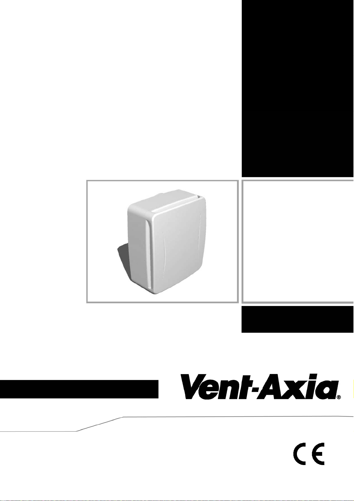
Quadra
Installation and Wiring Instructions
Stock Ref. N°
Quadra TP 439251
Quadra TM 439253
Quadra HTP 439181
220-240V~50Hz
PLEASE READ INSTRUCTIONS IN CONJUNCTION WITH ILLUSTRATIONS. PLEASE SAVE THESE
INSTRUCTIONS.
IPX4
Page 2

Technical Specifications (Tested at 240 VAC @ 50Hz):
Air Performance: 6, 9, 12, 15, 30 or 60 l/s (22, 32, 43, 54, 108 or 216 m³/h).
Power consumption: 3 - 45W.
Exhaust spigot diameter: Ø100mm.
Installed size: 260 x 230 x 112 mm (when surface mounted)
Features:
Surface mountable.
Can be flush mounted with optional accessory kit (439256).
Optional Filter available as an accessory (439927).
Option to boost from constant trickle or from off.
Three trickle speed options available, selectable during installation (6, 9 or 12 l/s).
Three boost speed options available, selectable during installation (15, 30 or 60 l/s).
LS connection (remote switch can switch the fan from the off or trickle state to boost).
Adjustable timer overrun ( 1-30 minutes approximately).
Model Specific Methods to Select Boost Speed: TP TM HTP
Pullcord
9
Movement sensor (P.I.R)
Adjustable relative humidity sensor
9
9
9
Page 3

INSTALLATION AND WIRING INSTRUCTIONS
IMPORTANT:
READ THESE INST RUCTIONS BEFORE COMMENCING THE INSTALLATION
DO NOT install this product in areas where the following may be present or occur:
• Excessive oil or a grease laden atmosphere.
• Corrosive or flammable gases, liquids or vapours.
• Ambient temperatures higher than 40°C or less than –5°C.
• Possible obstructions which would hinder the access or removal of the Fan.
SAFETY AND GUIDANCE NOTES
A. All wiring to be in accordance with the current I.E.E. Regulations, or the appropriate standards
of your country and MUST be installed by a suitably qualified person.
B. The Fan should be provided with a local isolator switch capable of disconnecting all poles,
having a contact separation of at least 3mm.
C. Ensure that the mains supply (Voltage, Frequency, and Phase) complies with the rating label.
D. The Fan should only be used in conjunction with the appropriate Vent-Axia products.
E. It is recommended that the connection to the fan connector terminals is made with flexible
cable.
F. When the Fan is used to remove air from a room containing a fuel-burning appliance, ensure
that the air replacement is adequate for both the fan and the fuel-burning appliance.
G. The Fan should not be used where it is liable to be subject to direct water spray for prolonged
periods of time.
H. Where ducted Fans are used to handle moisture-laden air, a condensation trap should be
fitted. Horizontal ducts should be arranged to slope slightly downwards away from the Fan.
I. This appliance is not intended for use by persons (including children) with reduced physical,
sensory or mental capabilities, or lack of experience and knowledge, unless they have been
given supervision or instruction concerning use of the appliance by a person responsible for
their safety.
J. Children should be supervised to ensure that they do not play with the appliance.
DESCRIPTION
As standard, the Quadra is suitable for panel/ceiling or wall installations and surface mounting
either in a horizontal or vertical plane. A Flush Mount Kit (439256) is available as an accessory.
Ø100mm ducting (flexible or rigid) can be attached providing rear exit as standard or side exit with
the Flush Mount Kit. Adaptors for rectangular ducting can be used. For wall installations a Wall Kit
(25 41 02 White / 25 41 00 Brown) can be used. Please see our catalogue or web site (www.ventaxia.com) for more information on alternative ducting and termination options. A Filter (439927) is
available as an accessory.
Page 4

A. INSTALLATION
A Backdraught Shutter Assembly is supplied. It is packed inside the product during transport. It is
designed to block the duct when the fan is off in order to prevent cold draughts from outside
entering the building. If you are going to set the fan up to extract air continuously (constant trickle),
you do not necessarily need it. To use it, push it on to the end of the exhaust Spigot with the
hinges on the flaps vertical (fig.1).
IMPORTANT: Be careful to avoid joists and hidden pipes or cables when cutting or drilling holes.
SURFACE MOUNTING (PANEL/CEILING)
1. Remove the Front Cover Assembly by slackening the 2 Cover Screws by 2 turns (fig.2.) Lift
the Cover Assembly away from the bottom edge then the top edge.
2. Cut a ∅105mm hole and suitable screw holes in the panel, ensuring that there is sufficient
space for the product to be installed and that the optional Filter (fig.3) could be removed for
cleaning. The cardboard fitment in the packaging can be used as a template.
3. Set-up the appropriate speed selection and other features as outlined in Section B SETUP
4. Remove the small Internal Cover that covers the Terminal Block in the top right corner (fig.3).
5. Attach the ducting to the Spigot and locate the Fan into the hole in the panel. Feed wiring
through the hole in the Chassis next to the Terminal Block as you do so. (fig. 4)
6. Secure into position using appropriate screws and rawl plugs.
7. Se lect and follow the appro p r iate wiring diagram i n Section C WIRING.
8. Replace the Internal Cover over the Terminal Block.
9. Ensure the Impeller rotates freely.
10. Replace the Front Cover Assembly and tighten the two screws.
11. Switch the mains power supply on and check the fan is operating correctly.
SURFACE MOUNTING (WALL)
For through-the-wall installations, a Wall Kit (25 41 02 White / 25 41 00 Brown) can be used.
1. Remove the Front Cover Assembly by slackening the 2 Cover Screws by 2 turns (fig.2.) Lift
the front assembly away from the bottom edge then the top edge.
2. Cut a ∅117mm hole through the wall, ensuring that there is sufficient space for the product to
be installed and that the optional Filter (fig.3) can be removed for maintenance. The
cardboard fitment inside the packaging can be used as a template.
3. Insert the wall sleeve with the larger diameter sleeve on the room-side and cement the ends
into position flush with the wall faces. The wall sleeve should be angled downwards, away
from the Fan, to allow any condensation to drain to outside.
4. Outside Grille (available separately): Using the Grille’s Back Plate as a template, mar k the
fixing hole centres on the wall. Drill and plug the wall and fix the Grille into position. Ensure
the louvres are pointing downwards.
5. Set-up the appropriate speed selection and other features as outlined in Section B SETUP.
6. Remove the small Internal Cover that covers the Terminal Block in the top right corner (fig 3).
7. Using the Fan Chassis as a template, carefully sliding the spigot into the Wall Liner, mark the
fixing hole centres on the wall.
8. Drill and plug the wall using the fixings provided.
9. Feed the wiring through the hole near the Terminal Block (fig.4) and secure the Fan into
position using the screws provided.
10. Select and follow the appropriate wiri n g diagram in Section C WIRING.
11. Replace the Internal Cover over the Terminal Block.
12. Ensure the Impeller (fig.3) rotates freely.
13. Replace the Front Cover Assembly and tighten the two screws.
14. Switch the mains power supply on and check the fan is operating correctly
.
Page 5
FLUSH MOUNTING (PANEL/CEILING)
A Flush Mount Kit (439256) is required.
1. Remove the Front Assembly by slackening 2 Cover Screws by 2 turns (fig.2). Lift the front
assembly away from the bottom edge then the top edge.
2. Mark and cut a rectangular hole 225mm (w) x 255mm (h) through the panel ensuring that
there is sufficient space for the product to be installed and that the optional Filter (fig.3) can
be removed for maintenance.
3. Remove the Back Box by removing the 4 screws. Replace it with the Frame from the
Accessory Kit 439256. (Fig 5).
4. Slide each Panel Clip in to the Chassis then pass each of the long Panel Clip Screws
(supplied in the kit) fully through the flange of the Chassis and screw in to the Panel Clips
(fig.6.) allowing enough space between the Panel Clip and the flange for the thickness of the
panel (so that the clips can spring open behind the panel).
5. Set-up the appropriate speed selection and other features as outlined in Section B SETUP.
6. Remove the Internal Terminal Block Cover that covers the Terminal Block in the top right
corner (fig 3 & 4).
7. Attach the ducting to the Spigot and locate into the hole in the panel, ensuring the cable is
fed into the Fan Chassis (fig.4) and the Panel Clips spring out behind the panel.
8. Secure into position by carefully tightening the 4 Panel Clip Screws. IMPORTANT: If power
tools are used, set them to the minimum torque setting or preferably use a manual
screwdriver. Do not over tighten.
9. Se lect and follow the appro p r iate wiring diagram i n Section C WIRING.
10. Replace the Internal Cover over the Terminal Block.
11. Ensure the Impeller rotates freely (fig.3).
12. Replace the Front Cover Assembly and tighten the two screws.
13. Switch the mains power supply on and check the fan is operating correctly.
B. SETUP
WARNING: THE FAN AND ANCILLARY CONTROL EQUIPMENT MUST
ISOLATED FR O M TH E PO W E R SU P P L Y D UR ING INSTAL LA TION OR
MAINTENANCE.
With the Cover removed the humidity adjustment, overrun timer adjustment, speed selection
switches and installation type switches are accessible in the bottom right corner of the product
(figs.4 & 7).
1. SELECTING THE CONSTANT TRICKLE SPEED (0, 6, 9 or 12 l/s)
This will determine the speed at which the fan will run most of the time except when boost is
activated by either the Pullcord, PIR, LS, or Relative Humidity Sensor.
i. Slide one
position) to select that flow rate for trickle speed.
ii. Setting all of those 3 switches to the left (off positions) will switch off the constant trickle
option (i.e the fan will normally be off and will switch to boost when the Pullcord, PIR, LS
or Humidity Sensor are activated).
2. SELECTING THE BOOST SPEED (15, 30 or 60 l/s)
This will determine the speed at which the fan will run when activated by either the Pullcord, PIR,
LS, or Relative Humidity Sensor.
i. Slide one
to select that flow rate for boost speed.
of the three switches marked as ‘Normal/Trickle Speed’ in fig.7 to the right (on
of the three switches marked as ‘Boost Speed’ in fig.7 to the right (on position)
BE
Page 6
3. TIMER ADJUSTMENT
The overrun time period is the length of time that the fan will continue to run at boost for after the
LS connection is switched off or the PIR (Quadra TM only) stops sensing movement. It is factory
set to approximately 15 minutes. The overrun time period may be adjusted from approximately 130 mins by altering the adjuster on the control PCB. (figs.4 & 7).
i. To REDUCE the operating time, turn the adjuster ANTI-CLOCKWISE.
ii. To INCREASE the operating time, turn the adjuster CLOCKWISE.
4. RELATIVE HUMIDITY ADJUSTMENT (HTP model only)
The fan’s Relative Humidity (RH) Set-Point is factory set to switch the fan on at about 72%RH.
i. To LOWER the Set-Point, turn the Humidity Adjuster (figs.4 & 7) ANTI-CLO CKWISE. This
makes the fan more sensitive to RH%, i.e. the fan will come on at a lower RH%.
ii. To RAISE the Set-Point, turn the Humidity Adjuster (figs.4 & 7) CLOCKWISE. This makes
the fan less sensitive to RH%, i.e. the fan will come on at a higher RH%.
C. WIRING.
WARNING: THE FAN AND ANCILLARY CONTROL EQUIPMENT MUST
BE
ISOLATED FR O M TH E PO W E R SU P P L Y D UR ING INSTAL LA TION OR
MAINTENANCE.
Use 0.75mm
2
cable
1. Se lect and follow the appro p r iate wiring diagram (figs. 9 & 10).
2. Additional controls, such as room mounted humidistats, pullcords, PIR sensors and
normal/boost switches, can be connected to the LS connection instead of the room lighting
circuit in fig 10 in order to make the fan boost. These accessories must switch a 240V 50Hz
live connection on when boost is wanted.
3. Use the Cable Clamp provided.
4. Check all connections have been made correctly and ensure all terminal connections are
securely fastened.
D. SERVICING AND MAINTENANCE.
WARNING: THE FAN AND ANCILLARY CONTROL EQUIPMENT MUST
BE
ISOLATED FR O M THE POWER SUP P L Y D UR I NG SERVICIN G O R
MAINTENANCE.
1. At intervals appropriate to the installation, the fan should be inspected and cleaned to ensure
there is no build up of dirt or other deposits.
2. If you have a Filter (fig.3), remove it by using a small, flat bladed screwdriver to lift the bottom
edge over the retaining edge (fig.2) and then slide the filter out.
3. Remove the Cover assembly by slackening the two cover screws (fig.2) by two turns and pull
it away. The Quadra has a built in safety feature. The motor will not run if the small round
magnet in the Cover is not detected (when the Cover is not fitted).
4. Remo ve the Impeller (fig.3) by pressing the two clips together in the middle and pulling it off
the Motor.
5. Wipe the outside of the fan with a damp (not dripping wet) cloth until clean.
6. Wash the Filter, Cover Assembly and Impeller in warm, soapy water if they are dirty. Do not
use abrasive cleaners. Dry the parts before replacing them.
7. Turn the power to the Fan back on.
The fan has sealed for life bearings, which do not require lubrication.
Page 7
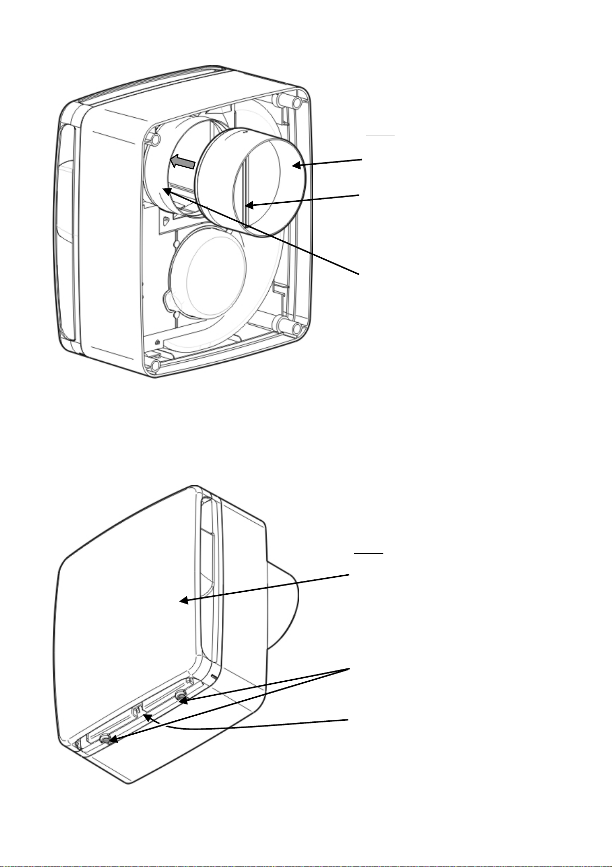
Fig.1.
Backdraught shutter assembly.
Flaps vertical.
Spigot.
Fig.2.
Cover Assembly.
Cover Screws.
Retaining edge for optional
Filter.
Insert flat bladed screwdriver in
here to remove Filter.
Page 8
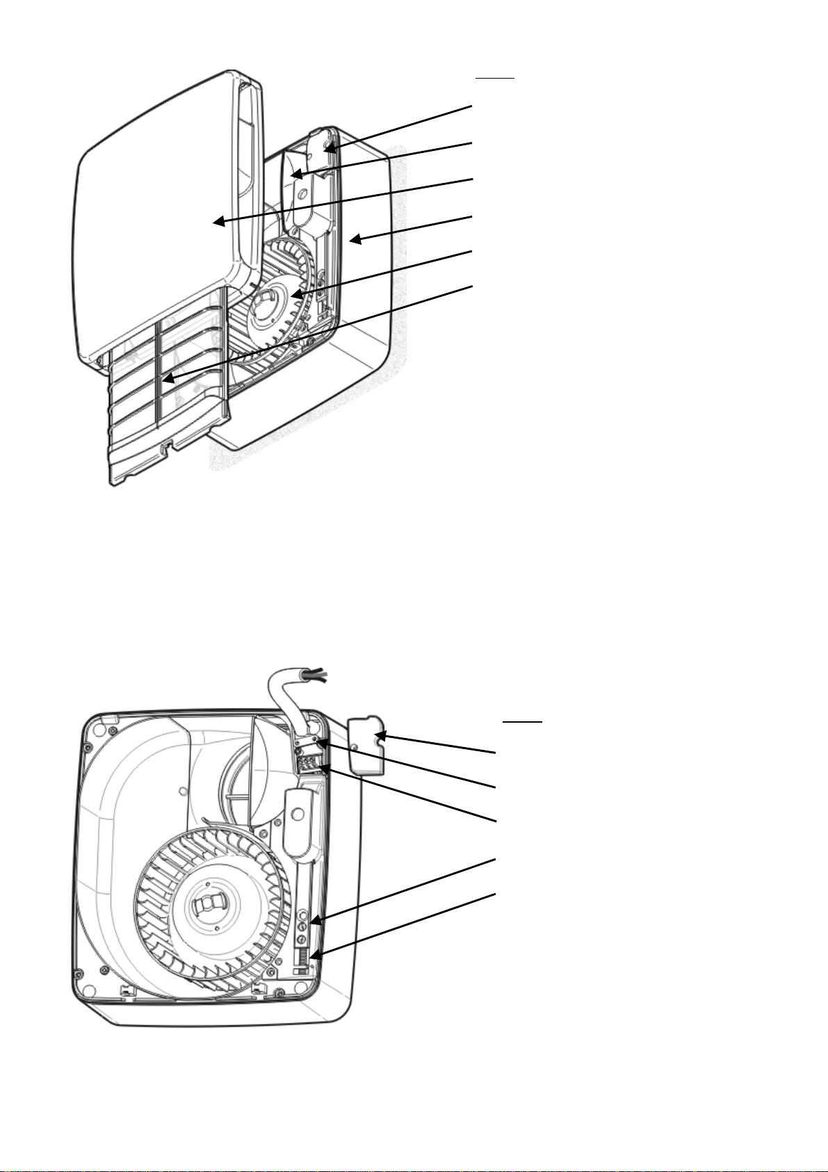
Fig.3.
Internal Terminal Block Cover.
Spigot.
Cover Assembly.
Chassis Assembly.
Impeller.
Optional Filter.
Fig.4.
Internal Terminal Block Cover.
Cable Clamp.
Terminal Block.
Timer and Humidity Adjustment.
Speed and Installation Type
Switches.
Page 9
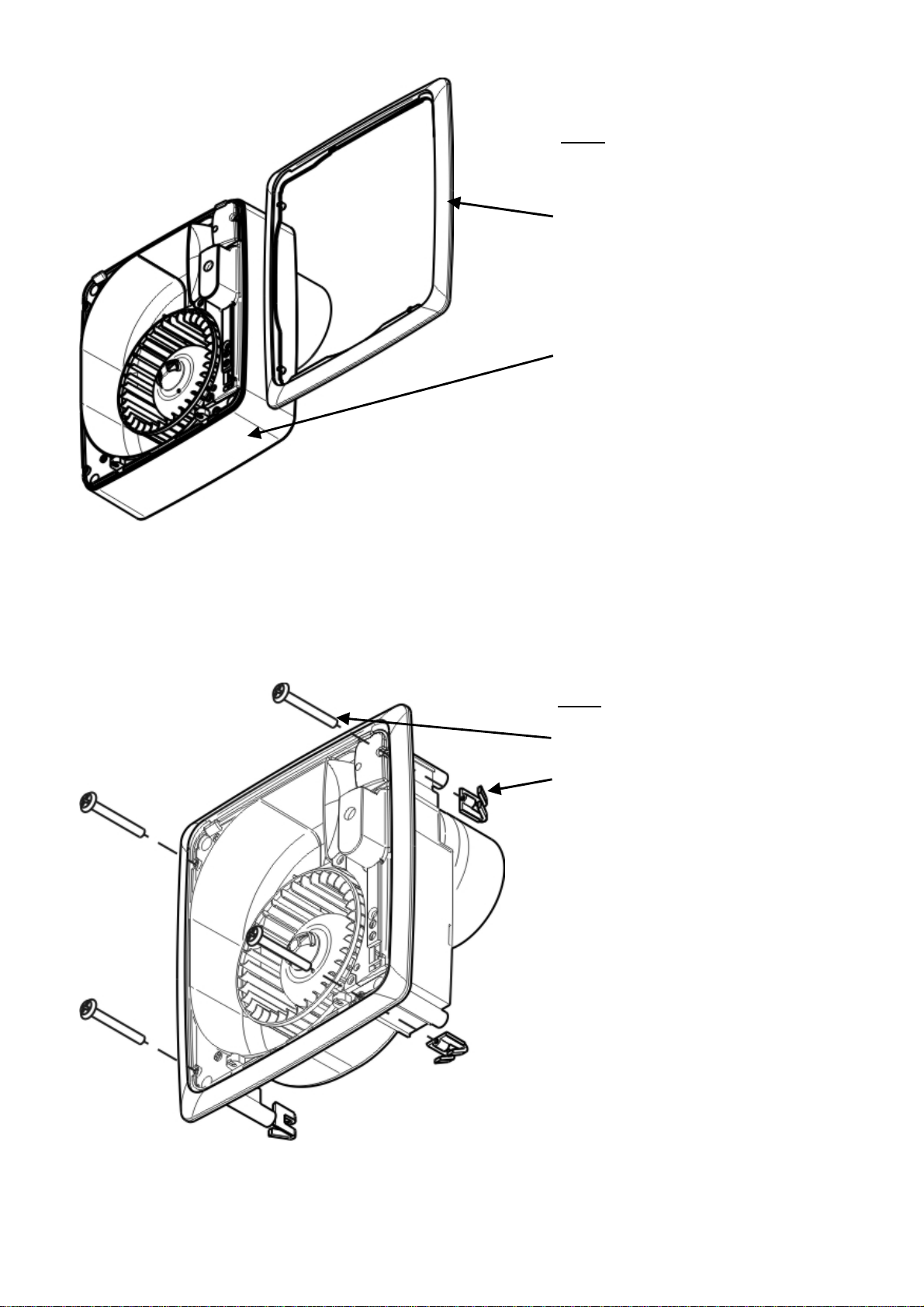
Fig.5.
Frame from optional Flush Mount Kit.
Back Box.
Fig.6.
Panel Clip Screw (4 off).
Panel Clip (4 off).
Page 10
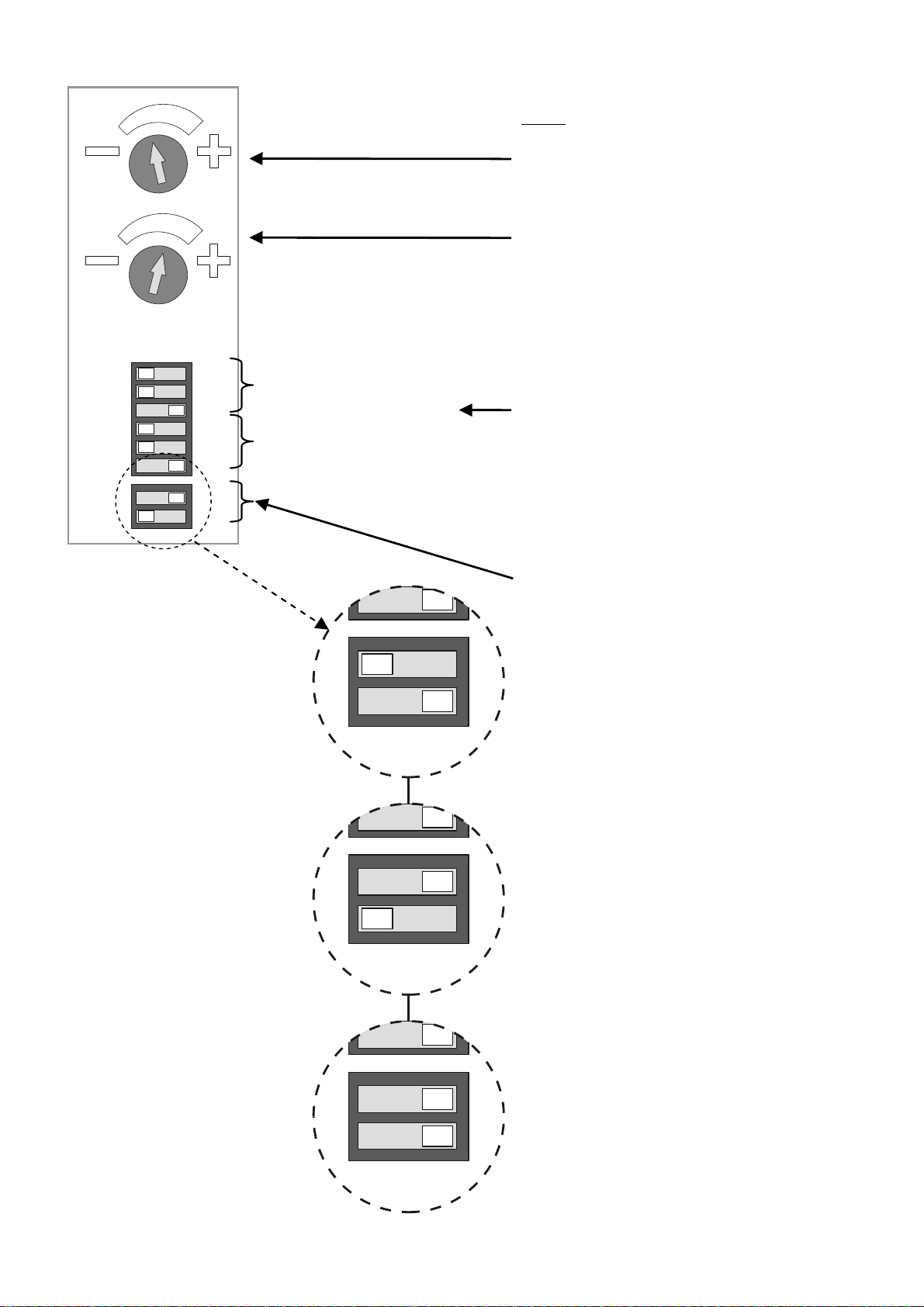
Off On
60
30
Boost Speed (l/s)
15
12
Normal/Trickle Speed (l/s)
9
6
Fig.7.
Timer adjustment.
Turn clockwise to increase overrun
timer.
Humidity Setpoint Adjustment.
Turn clockwise to raise set point.
Speed Selection Switches.
(Example shown is boost speed of
15 l/s and normal/trickle speed of 6
l/s.)
Installation Type Selection Switches:
Í Through the wall installation.
Í 1.5m Ø100mm ducting with one
90° bend and a wall grille.
Í 3m Ø100mm ducting with two
90° bends and a wall grille.
Page 11
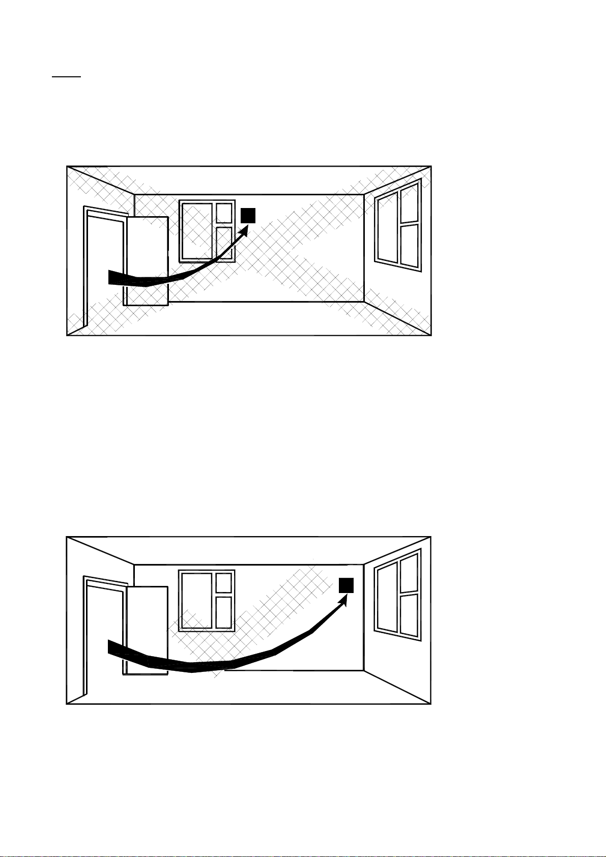
Fig 8.
Siting of the fan.
2
3
Page 12
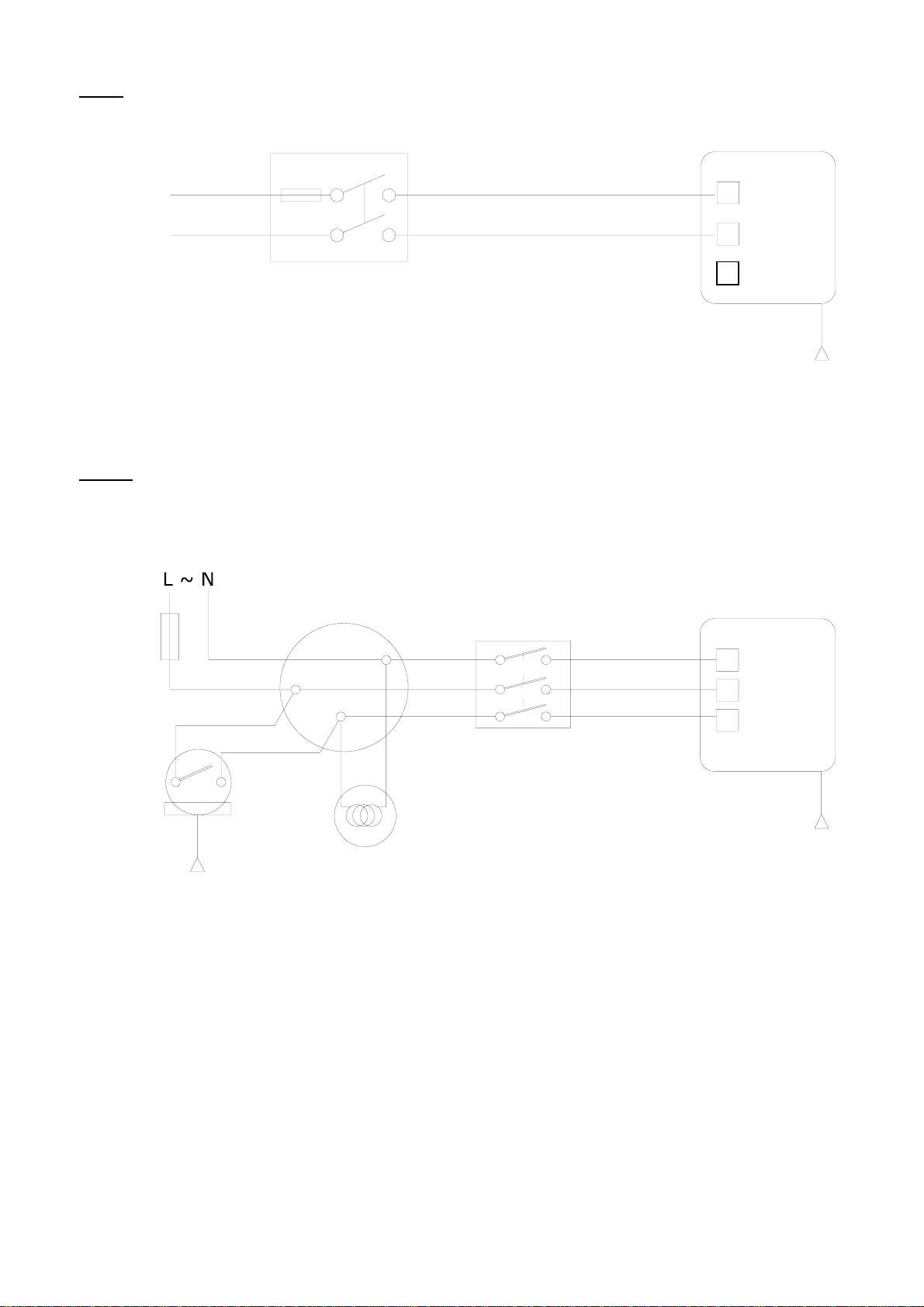
Fig 9. Wiring diagram without LS connection.
1 Phase Supply
(220-240V 50 Hz)
Fig 10.
For details of the warranty and returns procedure please refer to www.vent-axia.com or write to
Vent-Axia Ltd, Fleming Way, Crawley, RH10 9YX
L
~
N
Wiring diagram with LS connection.
1 Phase Supply
(220-240V 50 Hz)
3A
Pull Cord
3A Fuse
2 Pole Isolator
Switch
Ceiling Junction
3 Pole Isolator
Switch
Lamp
Fan
L
N
Pull Cord
(if applicable)
Fan
N
L
Ls
Pull Cord
(if applicable)
abc
Head Office: Fleming Way, Crawley, West Sussex, RH10 9YX.
Tel: 01293 526062 Fax: 01293 551188
UK NATIONAL CALL CENTRE, Newton Road, Crawley, West Sussex, RH10 9JA
SALES ENQUIRIES: Tel: 0844 8560590 Fax: 01293 565169
TECHNICAL SUPPORT: Tel: 0844 8560593 Fax: 01293 539209
439213 A 1108
 Loading...