

Page 1

Acoustic
Fans
Twin
In-line Duct Fan Range (QPTW)
Installation and Wiring Instructions
PLEASE READ ALL INSTRUCTIONS CAREFULLY BEFORE STARTING
INSTALLATION.
THESE INSTRUCTIONS SHOULD BE LEFT WITH THE END USER.
QPTW100C
QPTW125C
QPTW150C
QPTW160C
QPTW200C
QPTW250C
QPTW315C
QPTW400C
QPTW500C
Page 2

READ AND SAVE THESE INSTRUCTIONS
PLEASE READ ALL INSTRUCTIONS CAREFULLY BEFORE STARTING INSTALLATION.
INSTALLATION AND WIRING INSTRUCTIONS SHOULD BE LEFT WITH END USER.
Air moving equipment may present mechanical, electrical or noise hazards. To minimize
risks associated with these potential hazards, it is essential that safety, installation,
operation and maintenance instructions are followed. Implementation of these
instructions should always be undertaken by technically competent personnel.
Potential mechanical hazards must be eliminated by guarding against access to the
rotating parts whilst the air moving equipment is operating. A range of guards are
available for this purpose from Vent-Axia.
Installation work, both mechanical and electrical, must be undertaken in accordance
with the safety and installation instructions before switching on the unit.
Maintenance work should not be attempted before first switching off and isolating the
fan and its control from the electrical supply and ensuring that it cannot be accidentally
turned back on again. It is essential to ensure that rotating parts have come completely
to rest before maintenance work commences.
Air moving equipment may generate unacceptable noise levels when in operation. It
may be necessary to take appropriate action to reduce sound levels. A range of products
are available for this purpose from Vent-Axia.
This appliance is not intended for use by persons (including children) with reduced
physical, sensory or mental capabilities or lack of experience and knowledge unless they
have been given supervision or instruction concerning use of this appliance by a person
responsible for their safety.
Young children should be supervised to ensure that they do not play with the appliance.
IMPORTANT
1. All electrical connections should be made by a properly qualified electrician. The
fan must be sited and connected in accordance with current I.E.E Wiring
Regulations, BS7671 (U.K.), or the appropriate standards in your country.
2. DO NOT use this appliance when the following are generated or present: Excessive
grease or oil laden air, corrosive or flammable atmospheres.
3. When the fan is installed in a room containing a fuel burning appliance, the
installer must ensure that the air replacement is adequate for both the fan and
the fuel burning appliance.
4. If a fan is used to supply air into a room, the installer must ensure that the fan
intake is located at least 600mm away from any flue outlet.
5. Site away from direct sources of heat. Ambient temperature range:-10oC to
+40oC.
6. When installing unit, take care not to damage electrical or other hidden utilities.
7.
Check the details on the rating label for correct voltage, frequency, speed, phase
insulation class and IP rating.
2
Page 3
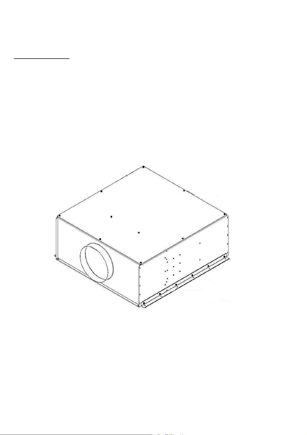
8. It is the responsibility of the installer to ensure that all aspects of system design
Fig.
1
: Support bracket used on the
QPTW
unit.
are taken into consideration.
9. Due to the weight of units it is recommended that two people are involved in the
installation.
FAN MOUNTING
1. Short duct runs terminating close to the fan (i.e. within 1.5m) require suitable
guards.
2. All QPTW units MUST be installed in a horizontal position.
3. Plan the installation carefully, taking into consideration the safety points noted
above, before securely fixing the fan using appropriate screws, bolts, rubber
bushes, etc.
4. A range of accessories is available from Vent-Axia to assist installation including
flexible connectors, mounting feet, anti-vibration mounts and attenuators.
5. For horizontal installations parallel fixing brackets are provided for both sides of
the unit (Fig. 1), and extra fixing holes are provided for additional hanger rods.
6. All twin units have a pair of exit airflow gravity shutters fitted which must be
orientated correctly to match the floor or ceiling mounting chosen for the
installation. As supplied from the factory, the gravity shutters are correctly fitted
for floor mounting the unit. If the unit is to be ceiling mounted, the shutter
assembly must be repositioned as fig. 2. To do this, remove the top cover to gain
access to the outlet plenum area. Remove the 6 x M6 screws holding the shutter
assembly in place then detach the assembly and rotate through 180 degrees. Then
refit the assembly using the 6 x M6 screws ensuring that the foam sealing strips
remain fitted correctly.
3
Page 4
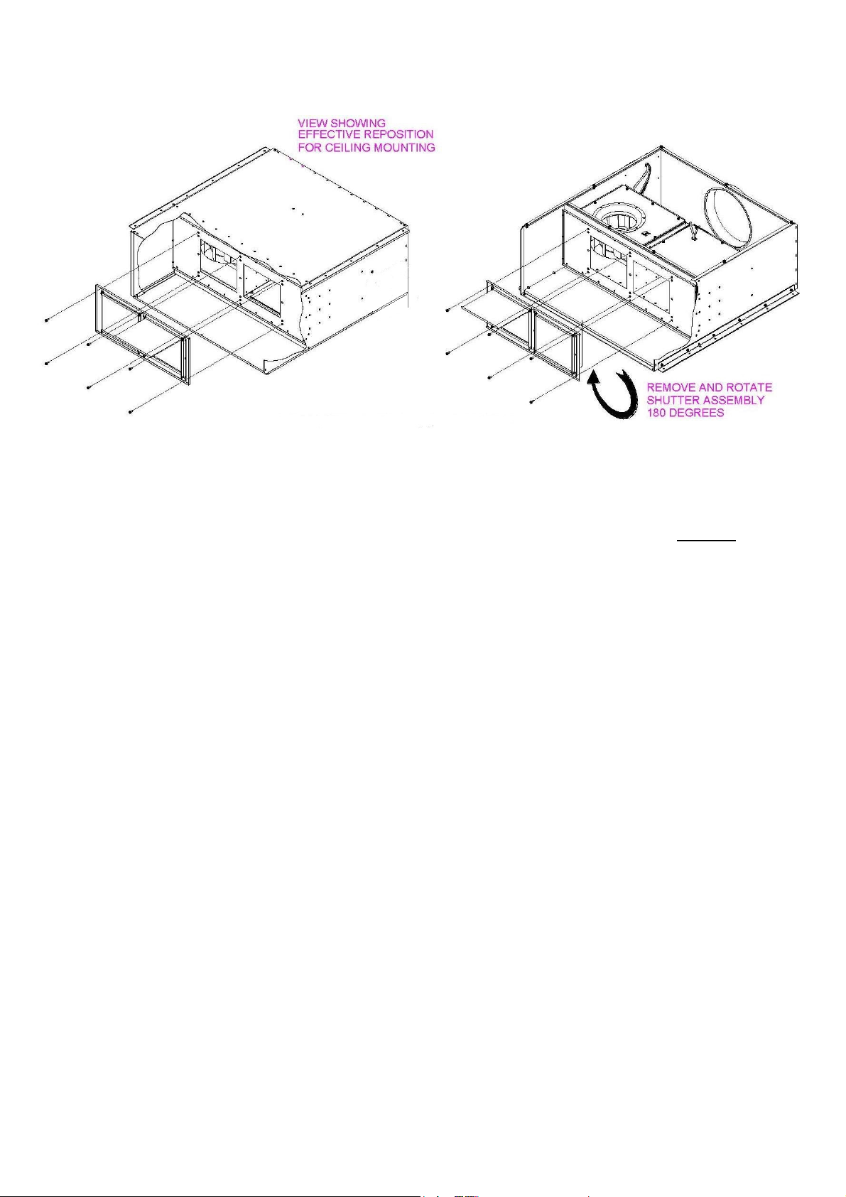
Fig.
2: Repositioning of shutter assembly.
GENERAL WIRING INSTRUCTIONS
WARNING – THE FAN AND ANY ANCILLARY CONTROL EQUIPMENT MUST BE
ISOLATED FROM THE POWER SUPPLY DURING INSTALLATION AND/OR
MAINTENANCE. THE EQUIPMENT MUST BE EARTHED.
1. All electrical connections should be made by a properly qualified electrician.
2. All wiring and connections must be carried out in accordance with current
regulations.
3. To comply with safety standards, an all pole isolator switch with a contact gap of
at least 3mm must be fitted adjacent to the fan.
4. Remove the lid of the QPTW to expose the supply connection terminal blocks
adjacent to the grommets in the wall of the QPTW.
5. The thermal protection device fitted is an automatic resetting type which must
always be included in the circuit. For ducted applications a manual reset is
required, an ancillary circuit will be required with the TK switch connected into the
circuit. See page 6 for instructions.
6. Connect the power supply from the local isolator (via any appropriate controls if
fitted) to the terminal blocks via the supplied cable gland using between 4.0mm
and 7.0mm diameter cable. Refer to the wiring diagrams and select the
appropriate connections for the fan, controller or other devices as being installed.
If in doubt please ask.
7. CAUTION: In order to avoid a hazard due to inadvertent resetting of the thermal
cut-out, this appliance must not be supplied through an external switching device,
such as a timer, or connected to a circuit that is regularly switched on and off by
the utility.
8. Ensure that all earth connections have been made.
9. After making connections to the terminal blocks, replace QPTW lid. Also ensure
that all cable gland nuts, grommets etc. have been used correctly to prevent the
ingress of water.
4
Page 5

NOTES ON RUNNING
Before Connecting the power supply and running the Fan Check…
Are all links and wiring complete as per wiring diagram?
Are all fixings secured?
Are all relevant guards fitted?
Are all Circuit protection devices fitted?
Are all Terminal box covers and sealing glands secured?
Are all Earth connections secured?
Check that no hazard exists for persons in the locality of the fan. Switch on the fan and
check that the fan rotation is correct as per the direction arrows on the fan plate/casing.
If not isolate power supply and check wiring. Check that the current (amps) taken by
the fan does not exceed the current shown on the rating plate.
INSTALLER AND ELECTRICAL CONTRACTOR RESPONSIBILITY
Vent-Axia Ltd, as suppliers of the equipment cannot be responsible for the final
installation and electrical connection of the product on site. We have made reasonable
effort to offer guidance and assistance but the installer and electrical contractor on site
have a responsibility for ensuring the equipment is safely and securely installed and
electrically/mechanically safe in accordance with statutory requirements.
The fans are supplied as a component to be incorporated into a ventilation system. The
final complete system installation that includes the fans MUST meet the requirements
of:Low voltage Directive 72/23/CEE
Machinery Directive 89/392/CE
Electromagnetic Compatibility Directive 89/336/CE
If the fan is installed in an area where there is possible danger to safety or health then
guards MUST be fitted.
Guards suitable for many applications are available from Vent-Axia Ltd.
Please remember that fans need maintenance, cleaning and inspection. Allow for
reasonable access for these operations to be carried out safely.
If in doubt, please ask.
ROUTINE INSPECTION/MAINTENANCE
THIS MUST BE UNDERTAKEN BY A COMPETENT PERSON.
ISOLATE UNIT FROM ELECTRICAL SUPPLY AND ENSURE THAT IT CANNOT BE
ACCIDENTALLY TURNED BACK ON.
1. We recommend that after three months the fan should be inspected and cleaned
to remove deposits on the impeller or motor. Thereafter, it should be checked and
cleaned periodically as experience dictates, or at least twice a year.
2. If a build-up of dirt/deposits is evident then this should be carefully cleaned off.
Please take care not to damage the fan or affect the balance of the impeller motor
assembly (balance weights may be fitted to the impeller).
3. The fan motors are fitted with ‘sealed for life’ bearings and should not require
maintenance under normal circumstances.
5
Page 6

Wiring Diagrams:
Important Notes:-
• For ducted applications the Thermal Protector (TK) must be connected into a
control circuit in order to ensure that the fan cannot restart before the fault
condition is cleared and the circuit manually reset.
• To comply with the above statement, this product is intended for use with Vent-
Axia controls listed below.
Vent-Axia Changeover Panel and Speed Controller stock reference numbers:
Product Changeover
Panel
Changeover
Panel with
duty share
eDemand
Changeover
Panel
QPTW100C 10314200 10314210 QPTW125C 10314200 10314210 QPTW150C 10314200 10314210 QPTW160C 10314200 10314210 QPTW200C 10314200 10314210 QPTW250C 10314200 10314210 QPTW315C 10314200 10314210 QPTW400C 10314200 10314210 444180
QPTW500C 10314200 10314210 444180
Product Auto
Transformer
controller
Auto
Transformer
controller
eDemand
Inverter
QPTW100C 10314103A - QPTW125C 10314103A - QPTW150C 10314103A - QPTW160C 10314103A - QPTW200C 10314103A - QPTW250C 10314103A - QPTW315C 10314103A - QPTW400C 10314103A RTRE35 444169
QPTW500C 10314105A RTRE60 444169
6
Page 7
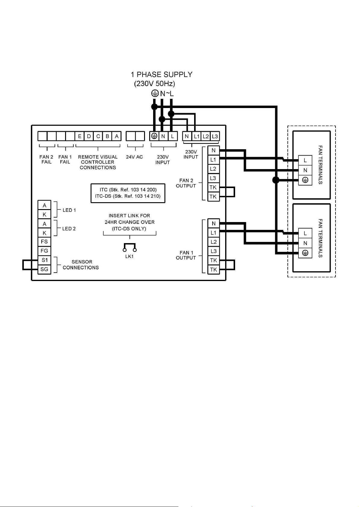
Fig. 1
QPTW100C, QPTW125C, QPTW150C, QPTW160C, QPTW200C, QPTW250C,
QPTW315C.
Connected to a changeover panel
7
Page 8
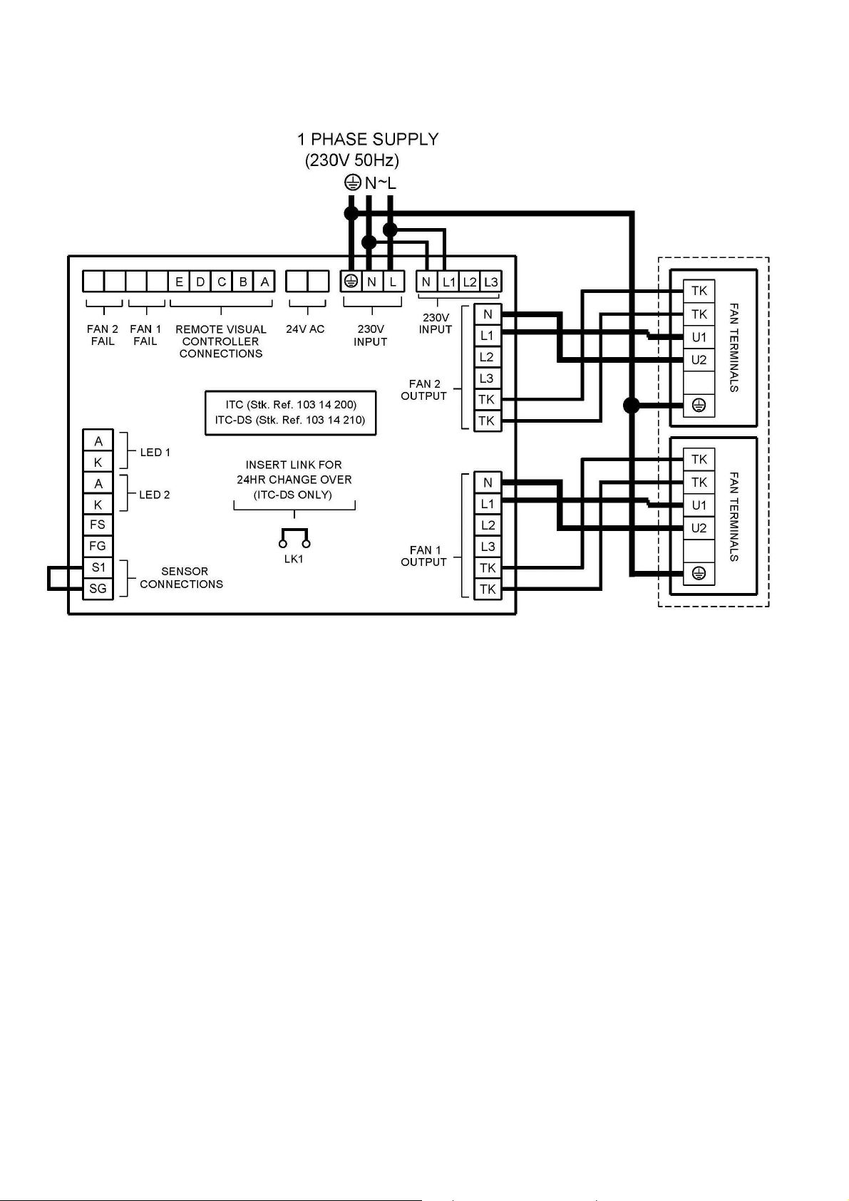
Fig. 2
QPTW400C, QPTW500C.
Connected to a changeover panel
8
Page 9

Fig. 3
QPTW100C, QPTW125C, QPTW150C, QPTW160C, QPTW200C, QPTW250C,
QPTW315C.
Connected to a changeover panel and auto transformer controller
9
Page 10

Fig. 4
QPTW400C, QPTW500C.
Connected to a changeover panel and auto transformer controller
10
Page 11
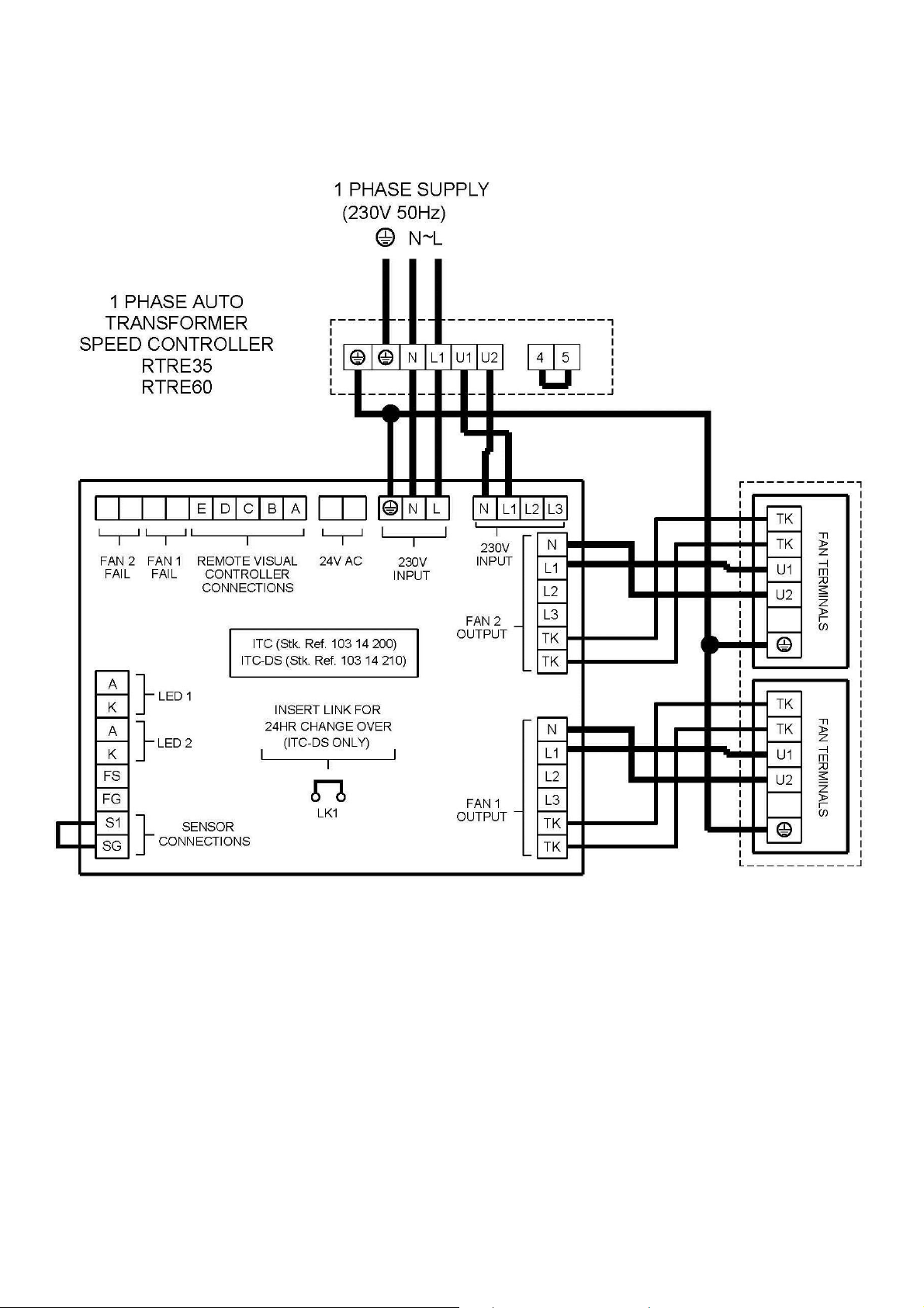
Fig. 5
QPTW400C, QPTW500C.
Connected to a changeover panel and auto transformer controller
11
Page 12
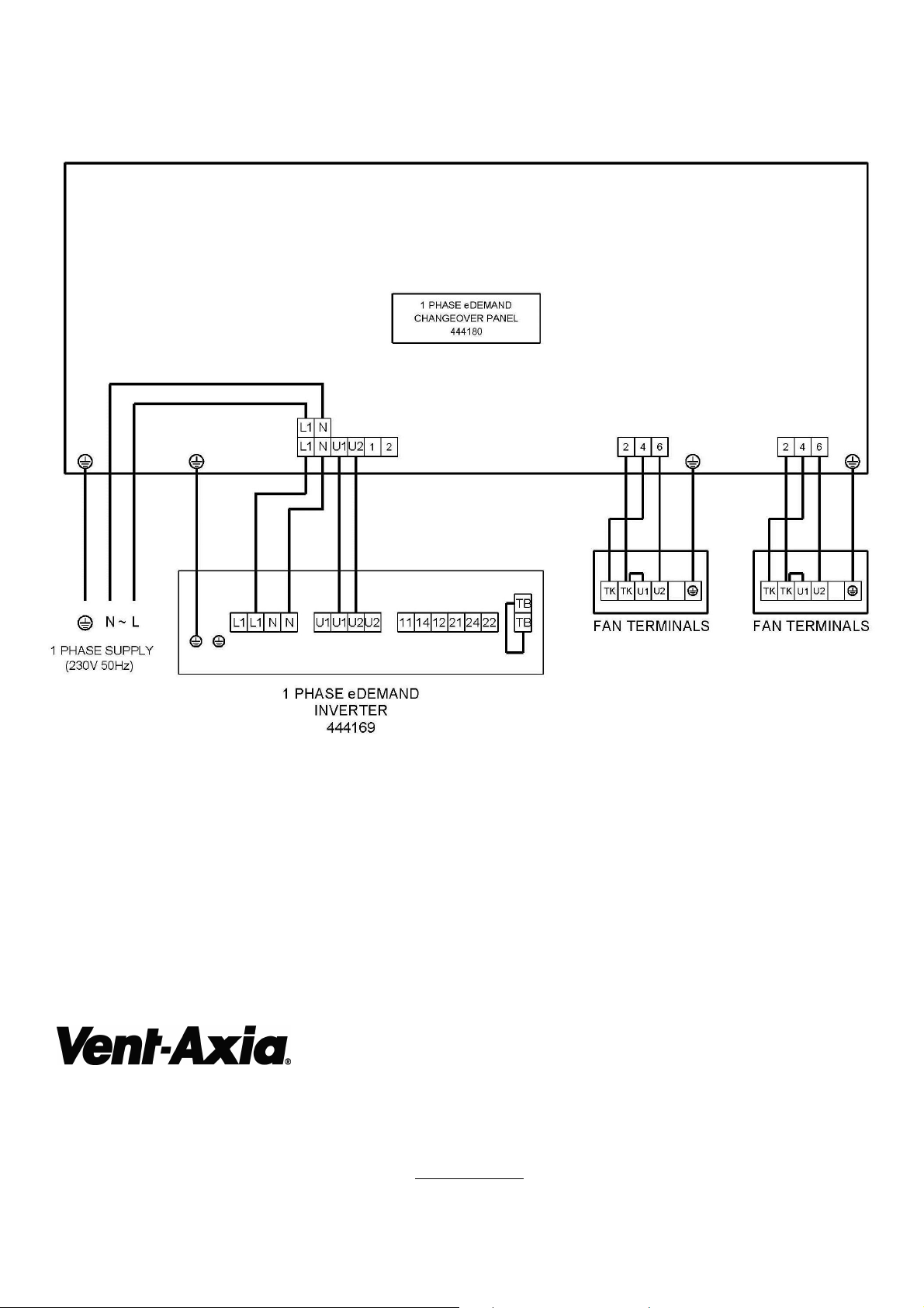
Fig. 6
QPTW400C, QPTW500C.
Connected to an eDemand changeover panel and eDemand inverter
Head Office: Fleming Way, Crawley, West Sussex, RH10 9YX.
UK NATIONAL CALL CENTRE, Newton Road, Crawley, West Sussex, RH10 9JA
SALES ENQUIRIES: Tel: 0844 8560590 Fax: 01293 565169
TECHNICAL SUPPORT: Tel: 0844 8560593 Fax: 01293 539209
For details of the warranty and returns procedure please refer to www.vent-axia.com or write to Vent-Axia Ltd, Fleming Way, Crawley, RH10 9YX
474349B 0716
12
 Loading...