

Page 1
Please leave these instructions with the user
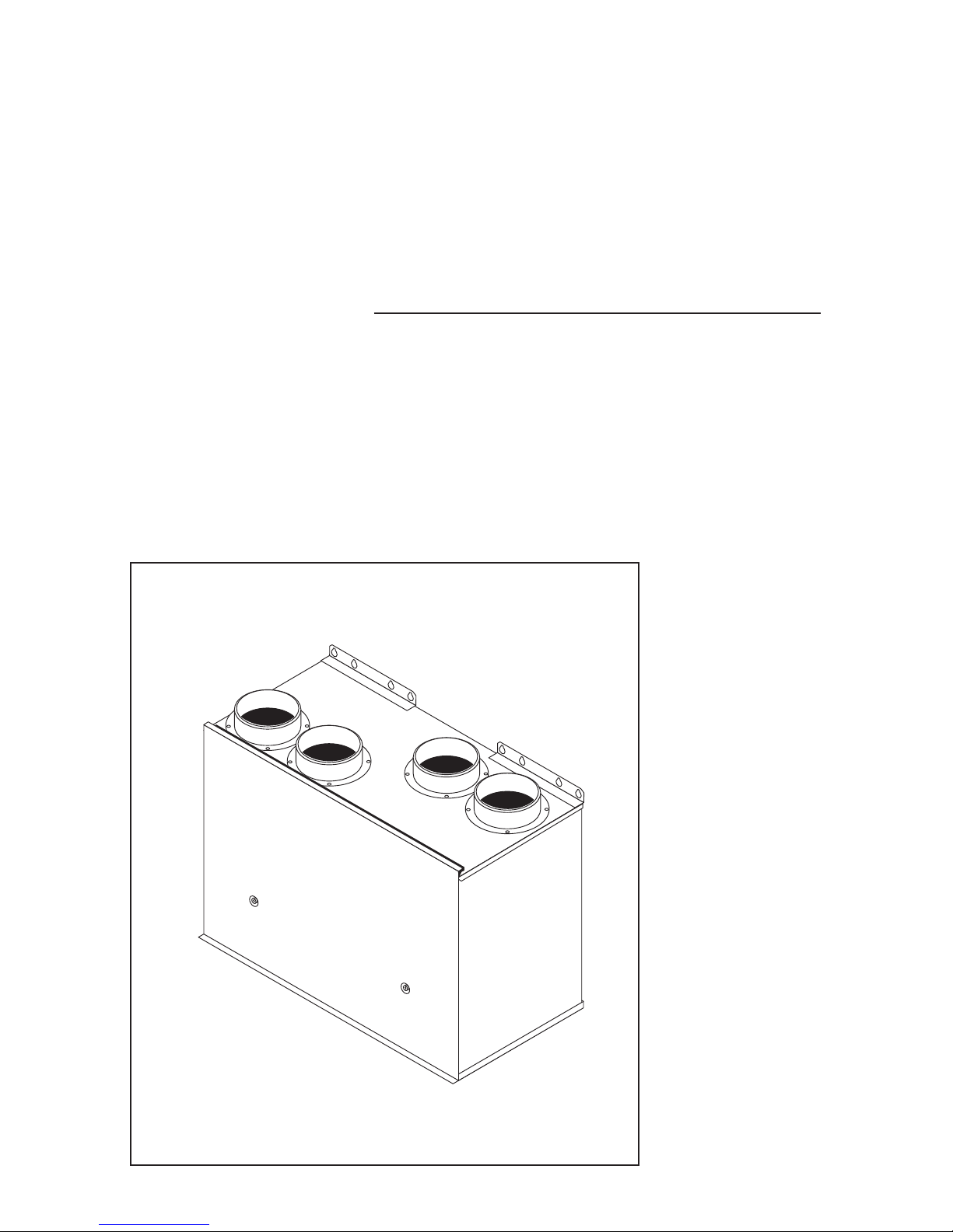
Whole House Ventilation System
with Heat Recovery
User, Installation & Servicing
Instructions
LoWatt HR204
ABC
Page 2
2
Contents
Section
Page
1.0 Safety and Guidance Notes
2.0 User Information
3.0 General Layout
4.0 Technical Data
5.0 Appliance Operation
6.0 Installation Requirements
7.0 Installation
8.0 Wiring Diagrams
9.0 Commissioning
10.0 Maintenance
11.0 Changing Components
12.0 Fault Finding
13.0 Short Parts List
3
4
5
6
8
9
12
15
18
19
20
22
24
Page 3
3
1.0 Safety and Guidance Notes
1. DO NOT install this product in areas where
the following may be present or occur:
-Excessive oil or a grease laden atmosphere.
-Corrosive or flammable gases, liquids or
vapours.
-Ambient temperatures higher than 40°C or
less than 5°C.
-Possible obstructions which would hinder the
access or removal of the product.
2. All wiring to be in accordance with the current
I.E.E. Regulations, or the appropriate standards
of your country and MUST be installed by a
suitably qualified person.
3. The LoWatt HR204 and accessories should
be provided with a local isolator switch capable
of disconnecting all poles, having a contact
separation of at least 3mm.
4. Ensure that the mains supply (voltage,
frequency, and phase) complies with the rating
label.
5. The LoWatt HR204 should only be used in
conjunction with the appropriate Vent-Axia
accessories.
6.When the LoWatt HR204 is used to remove air
from a room containing a fuel-burning
appliance, ensure that the air replacement is
adequate for both the LoWatt HR204 and the
fuel-burning appliance.
7. The LoWatt HR204 should not be fitted where
it is liable to be subject to direct water spray.
8. This appliance is not intended for use by
persons (including children) with reduced
physical, sensory or mental capabilities, or lack
of experience and knowledge, unless they have
been given supervision or instruction
concerning use of the appliance by a person
responsible for their safety.
9. Children should be supervised to ensure that
they do not play with the appliance.
10. The power supply to the unit and its
accessories should always be switched off
before removing the cover or ducting.
Page 4
4
2.0 User Information
Read the instructions fully before installing
or using the appliance.
This appliance must be installed in
accordance with the manufacturer's
instructions and the regulations in force.
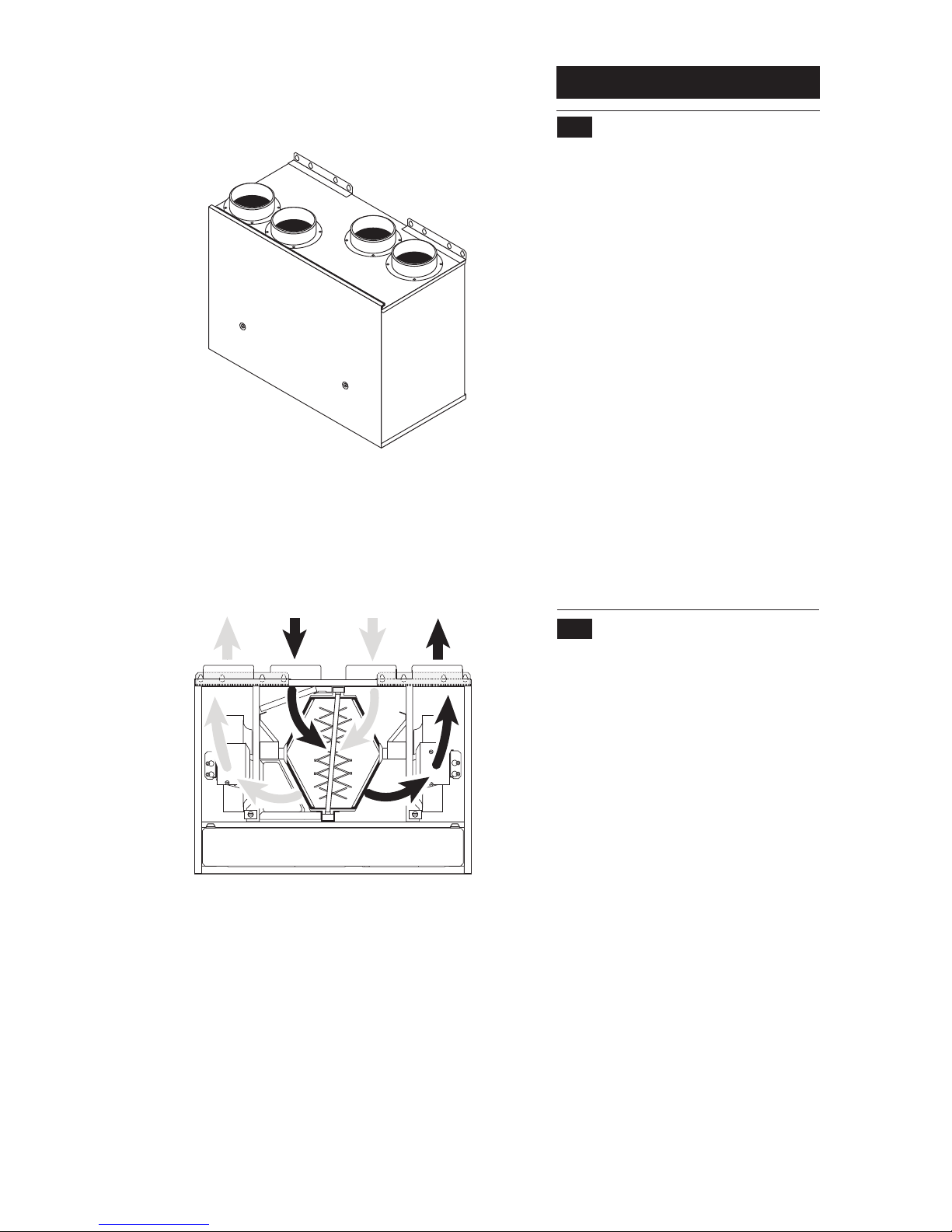
The LoWatt HR204 is a mechanical ventilation
with heat recovery (MVHR) unit. The unit
provides continuous extraction of stale air
from the dwelling, typically from the
bathroom and from the kitchen. The stale
air passes through the heat exchanger
before being ducted to outside.
Fresh air from the outside is continuously
drawn into the unit and passed through a
filter and then into the heat exchanger. In
the heat exchanger the fresh air is prewarmed and ducted into the dwelling,
typically to living rooms / bedrooms.
Fig. 1
This product should not be disposed of with
household waste. Please recycle where
facilities exist. Check with your local
authority for recycling advice.
For cleaning and servicing instructions,
refer to section 9, page 19.
Exhaust
Out
Fresh Air
In
Hot Stale
Air In
Warm Air
Out
Applicable only to products installed and
used in the United Kingdom. For details of
the Guarantee outside of the United Kingdom
contact your local supplier.
Vent-Axia guarantees this product for two
years from the date of purchase against faulty
material or workmanship. In the event of any
part being found to be defective, the product
will be repaired, or at the Company's
discretion the product will be replaced
without charge, provided that the product:
1). Has been installed and used in
accordance with the instruction given with
each unit.
2). The electricity supply complies with the
rating label.
3). Has not been misused, neglected or
damaged.
4). Has not been modified or repaired by any
person not authorised to do so by Vent-Axia.
IF CLAIMING UNDER THE TERMS OF THE
GUARANTEE
Please return the complete product, carriage
paid to your original supplier by post or in
person. Please ensure that it is adequately
packed and accompanied by a letter clearly
marked 'Guarantee Claim' stating the nature
of the fault and providing proof of the date
and source of purchase.
2. 2 The Vent-Axia Guarantee
2. 1 General
Page 5
5
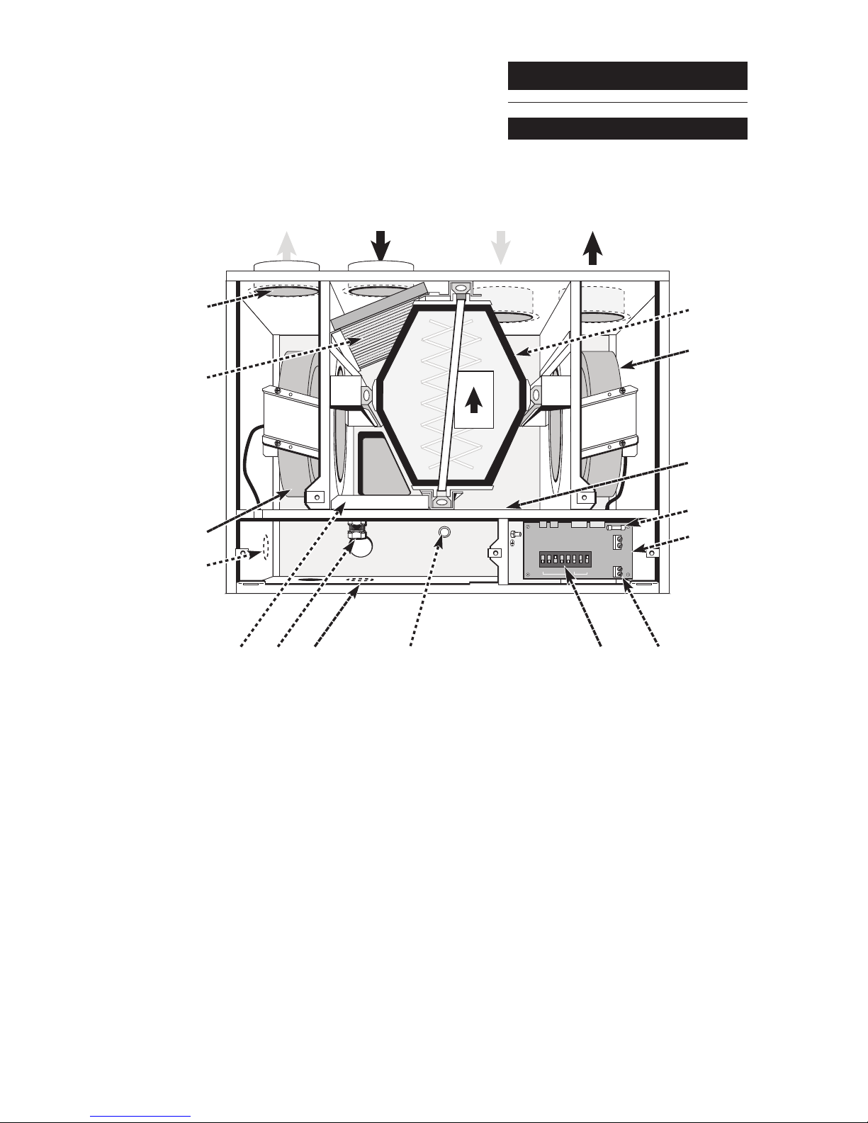
3.0 General Layout
LoWatt HR 204
Exhaust
out to
atmosphere
Fresh air
in from
atmosphere
N
L
1
2
1 234
5
6
7
8
Normal
Boost
1 234
5
4
5
6
ON
FRONT
UP
Hot stale air
extracted
in from
wet rooms
Warmed fresh
air supplied
out to
dry rooms
1
2
810
911
15
67
14
4
13
5
12
Fig. 2
3
1. Heat exchanger
2. Fan (fresh air in)
3. Rating label
4. Fuse
5. Speed select PCB
6. Accessory switch connection
7. Dip switch for speed selection
8. Lower fixing hole
9. Alternative outlet for condensate (bottom)
10. Condensate drain (Ø15mm)
11 Condensate tray
12 Alternative outlet for condensate (side)
13 Fan (extraction)
14. Air filter
15. Duct connections (4 off)
Page 6
6
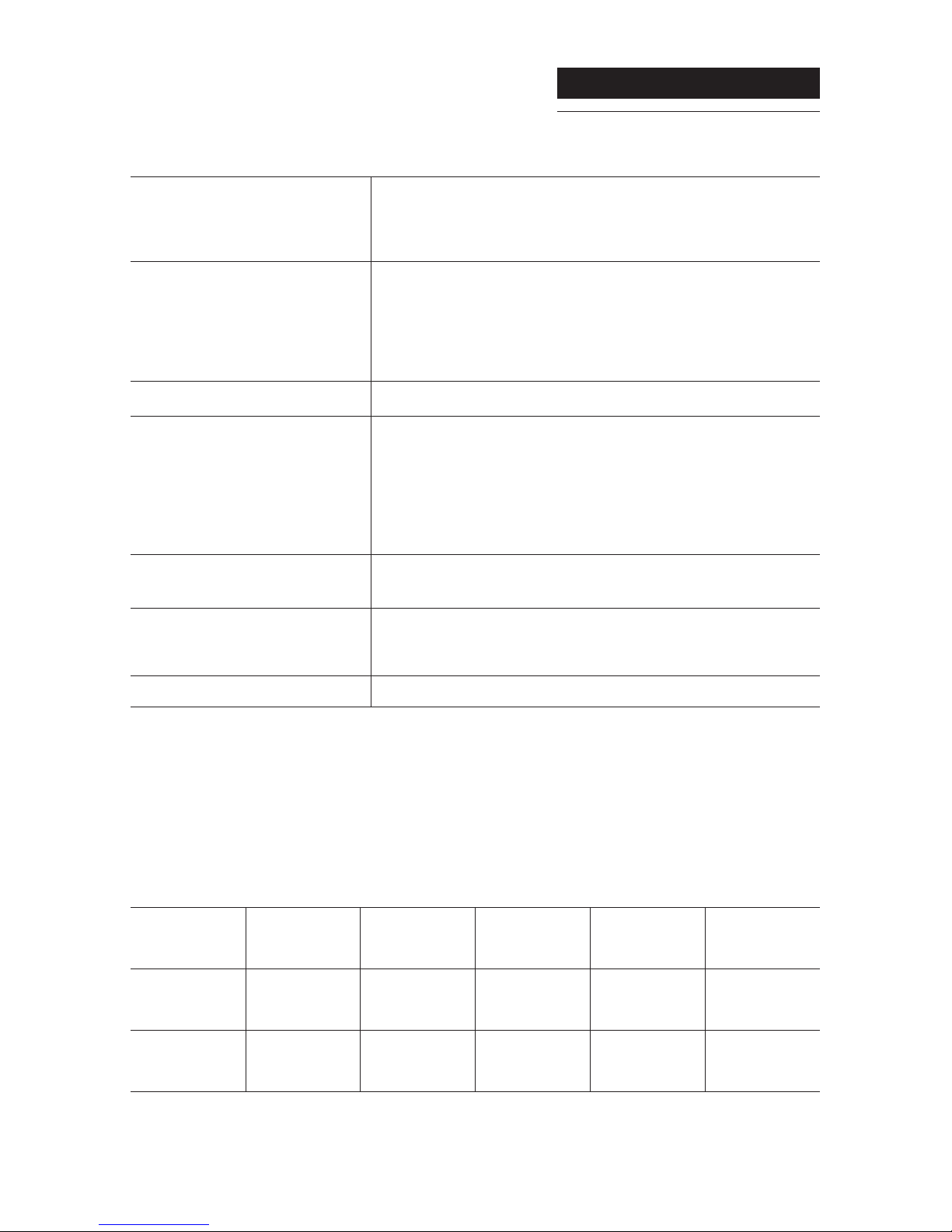
4.0 Technical Data
Dimensions (mm)
Height
Width
Depth
Minimum clearances (mm)
Both sides
Above casing
Below casing
Front for servicing
Front in operation
Lift weight (kg)
Power consumption @ 0Pa (watts)
Suitable for Ø100mm circular ducts.
Suitable for Ø15mm pipe.
220-240V ~50Hz
3 Amps
3.15 Amps
EU2
412
552
285
5
200
100
250
None
17
Speed 1
Speed 2
Speed 3
Speed 4
Speed 5
Speed 6
10
13
21
35
56
75
Duct connections
Condensate connection
Electrical supply
External fuse rating
Internal fuse rating
Filtration
Appliance must be connected to an earthed supply
Fig. 4
SAP Appendix Q Test Results
As tested and published by BRE (Building Research Establishment).
www.sap-appendixq.org.uk
Exhaust
terminal
configuration
Fan speed
setting
Total flow
supply rate (l/s)
Total exhaust
flow rate (l/s)
Specific fan
power (W/l/s)
Heat recovery
efficiency (%)
Kitchen + 1
additional wet
room
Kitchen + 2
additional wet
rooms
2
3
15.0
21.0
15.0
21.1
0.81
0.95
63
57
Fig. 3
Page 7
7
4.0 Technical Data
412
552
Mounting
Brackets
Side View
Ø98
100
280
285
4
Lower
Fixing Hole
Exhaust
Out
Fresh Air
In
Hot Stale
Air In
Warm Air
Out
Air Flow System
Clean Air
Stale Air
Front View
Fig. 6
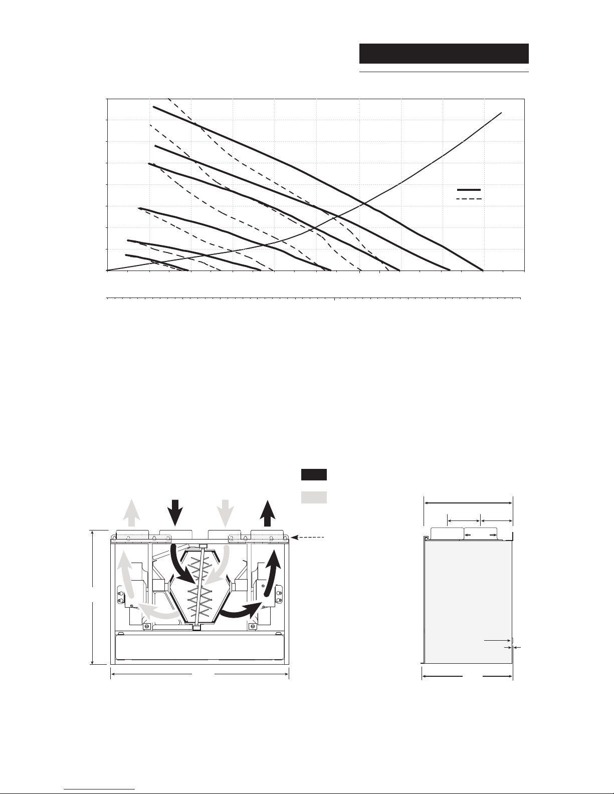
Flow Rate Vs Pressure Chart
Fig. 5
The unit has six speeds. One of the lowest five can be selected for normal speed. One of the top 3 can be
selected for boost speed. The performance curve chart gives the ventilation rates at each fan speed compared
to the pressure drop of the system.
102
100Pa @
100m³/h
0
50
100
150
200
250
300
350
400
0 20 40 60 80 100 120 140 160 180 200
Pressure (Pa)
0 5 10 15 20 25 30 35 40 45 50
Volume (l/s)
55
Volume (m³/h)
Extract
Supply
1
2
3
4
5
6
Page 8
8
5.0 Appliance Operation
On normal running the fans run at the speed
set during commissioning (speed 1, 2, 3, 4 or 5).
If the external controls call for boost operation
the fans automatically run at the boost speed &
increase the air movement of both exhaust &
inlet air.
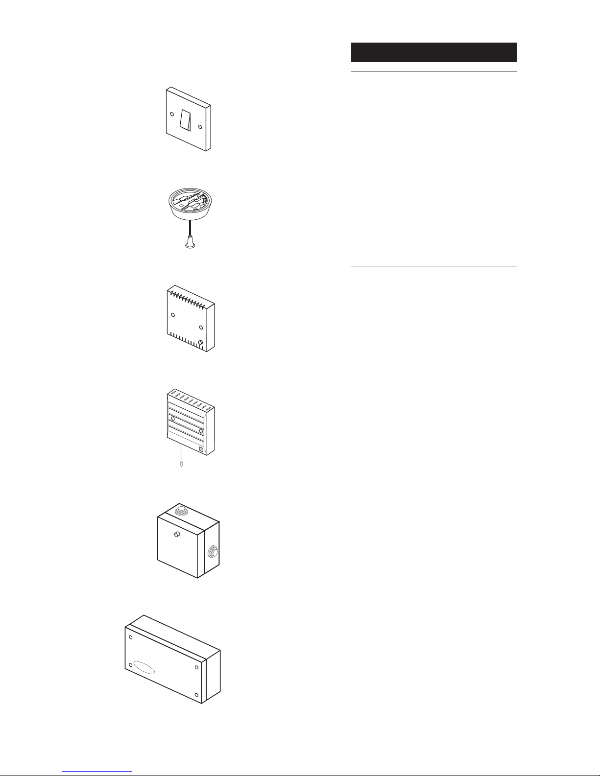
Optional Extras.
External Controls.
Normal/boost
Switch
NBSW
N
m
o
r
al
B
o tos
Humidity Sensor
HS6
Normal/boost
Pull Cord Switch
PCSW
CMSM control
TIM2 timer
The LoWatt HR204 can only be connected to
external controls with an uncommitted relay.
If the fans become jammed, then the
electronics will sense the reduction in speed
(rpm) and stop the electrical supply to the
motors to prevent overheating. The unit will
check the ability of the fan to rotate every
couple of seconds.
Air is then moved through the unit (see Fig 6).
Humidity Sensor
Ecotronic
Page 9
9
6.0 Installation Requirements
6.1 Location and Site Requirements
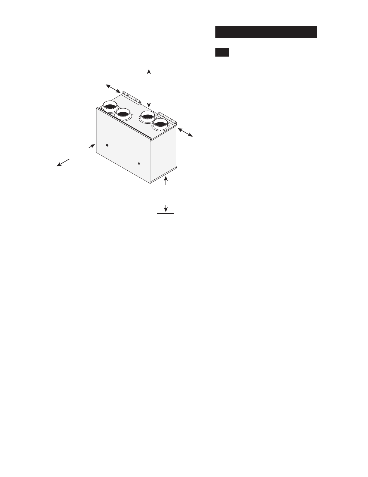
All dimensions
in mm
Total required
(including clearances)
Height - 692
Width - 562
Depth - 530
Minimum top
clearance
for servicing
200
Minimum
side
clearance
5
Minimum
side
clearance
5
Minimum bottom
clearance
100
Minimum front
clearance
for servicing
250
Fig. 7
Clearances
1. Read the instructions fully before installing or
using the appliance.
2. The installation must be carried out in
accordance with the manufacturer's instructions
by a competent person and comply with the
relevant Building Regulations and the current
I.E.E Wiring Regulations.
3. Duct systems should be installed in
accordance with BRE Digest 398 and CIBSE
guides.
4. Consideration must be given to the position
of the ductwork connections, the electrical
connection and the condensate pipe
connection.
5. The exhaust duct must pass through an
outside wall or roof and discharge to
atmosphere in a suitable position. The clean air
inlet duct must pass through an outside wall or
roof and be suitably positioned to provide an
adequate fresh air supply from atmosphere.
6. The ventilation for any open flued appliance
must always be considered before siting the
extract and inlet vents. The vents must also be
sited away from other flue terminals, ventilators
etc. on the outside of the dwelling. In addition,
there shall be adequate ventilation of the kitchen
when a cooker hood is used at the same time as
appliances burning gas or other fuel. The
exhaust air duct must not be discharged into a
flue which is used for exhausting fumes from
appliances burning gas or other fuels. Refer to
the relevant current British Standard Codes of
Practice, Part J of the Building Regulations
(England and Wales) and, in Scotland, OFTEC
Technical Information Sheet TI/112.
7. The LoWatt HR204 is not suitable for
installation above any cooking appliance or with
any extraction system servicing a cooking
appliance.
8. If the unit is fitted in a room containing a bath
or shower then reference should be made to the
current I.E.E Wiring Regulations.
9. A flat vertical area 692mm high x 562mm wide
is required for installation.
10. It is important that any door or cupboard
front covering the LoWatt HR204 is easily
removable by the user as access for regular
cleaning is required.
11. Check that the information on the rating
label is compatible with the supply. See Fig 2.
12. The addition of anything that may interfere
with the normal operation of the appliance could
invalidate the appliance warranty and infringe
regulations.
Note: Clearances do not take into
account any acoustic mat that may
be fitted between the unit and the
wall.
Page 10
10
6.0 Installation Requirements
6.2 General
1. The LoWatt HR204 has a choice of 5 normal
speed settings and 3 boost speed settings. The
performance curve chart (Section 4, Fig.5)
gives the ventilation rates at each fan speed
setting compared to the pressure drop of the
system.
2. The transmission of noise along ducts should
be reduced by fitting noise attenuation ducts.
(FS100. Part No 370426.)
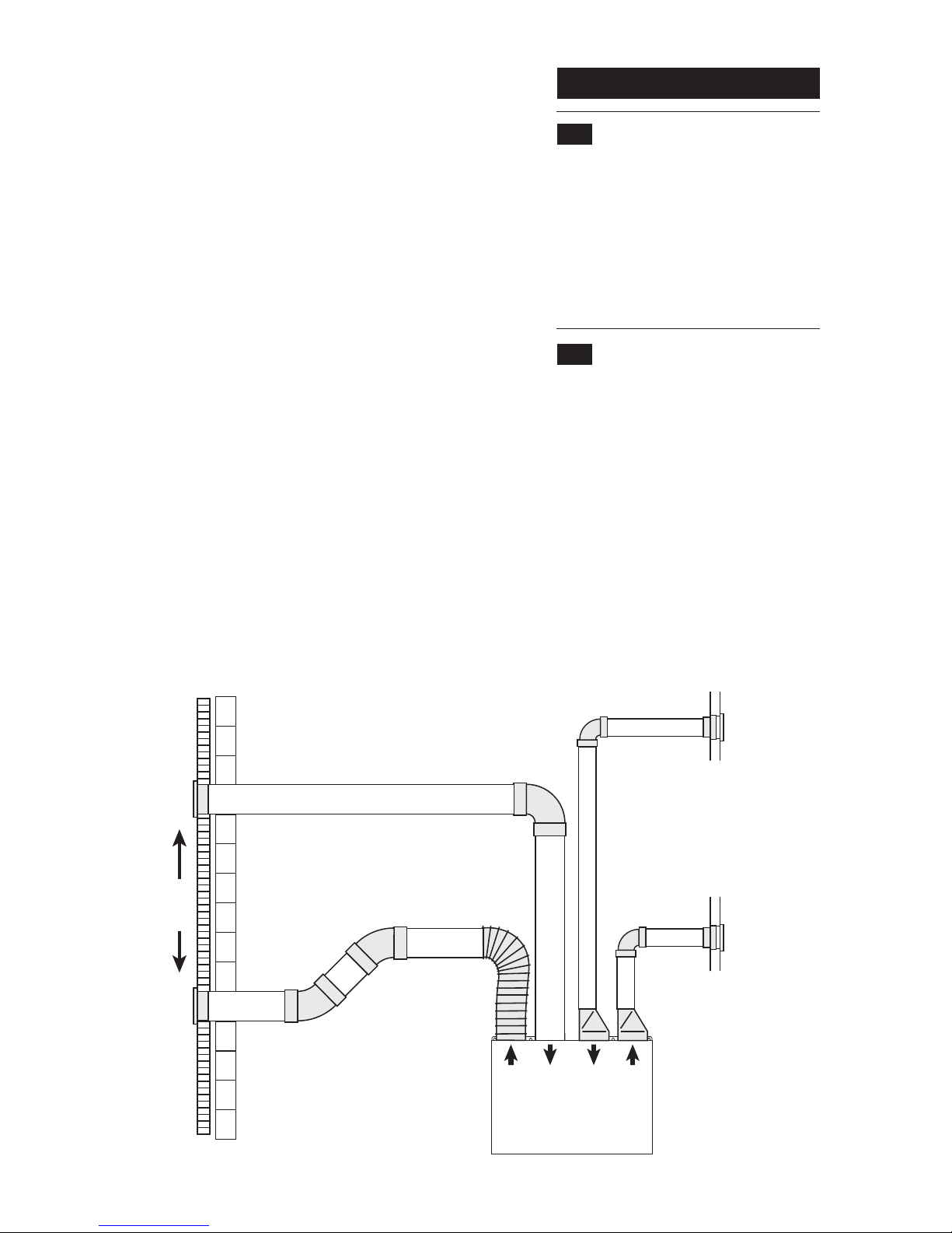
6. 3 Ducting
1. The outside exhaust duct and outside air
intake duct should be sited a minimum of 2
metres apart to minimise the risk of exhaust
air being drawn back into the house.
2. The duct work system should be sized and
installed to minimise the pressure loss along it.
3. Using larger diameter pipes and keeping the
number of bends and fittings used to a minimum
will reduce the pressure drop and allow the unit
to be set at a lower fan speed.
5. Ducting should be insulated in cold areas to
minimise heat losses. All duct joints should be
suitably taped to ensure an air tight seal.
Exhaust out
Fresh air in
Hot stale air in
Warm air out
Examples of different ducting & fittings
Bathroom
Living room or
bedroom
Terminals
minimum
2m apart
Outside
Wall
LoWatt HR204
Fig. 8
or kitchen
4. Bend radii for flexible ducting, measured to
the inside of bends, should be kept to at least
1x the duct diameter.
Page 11
11
6.0 Installation Requirements
N
L
1
2
1 234
5
6
7
8
Normal
Boost
1 234
5
4
5
6
ON
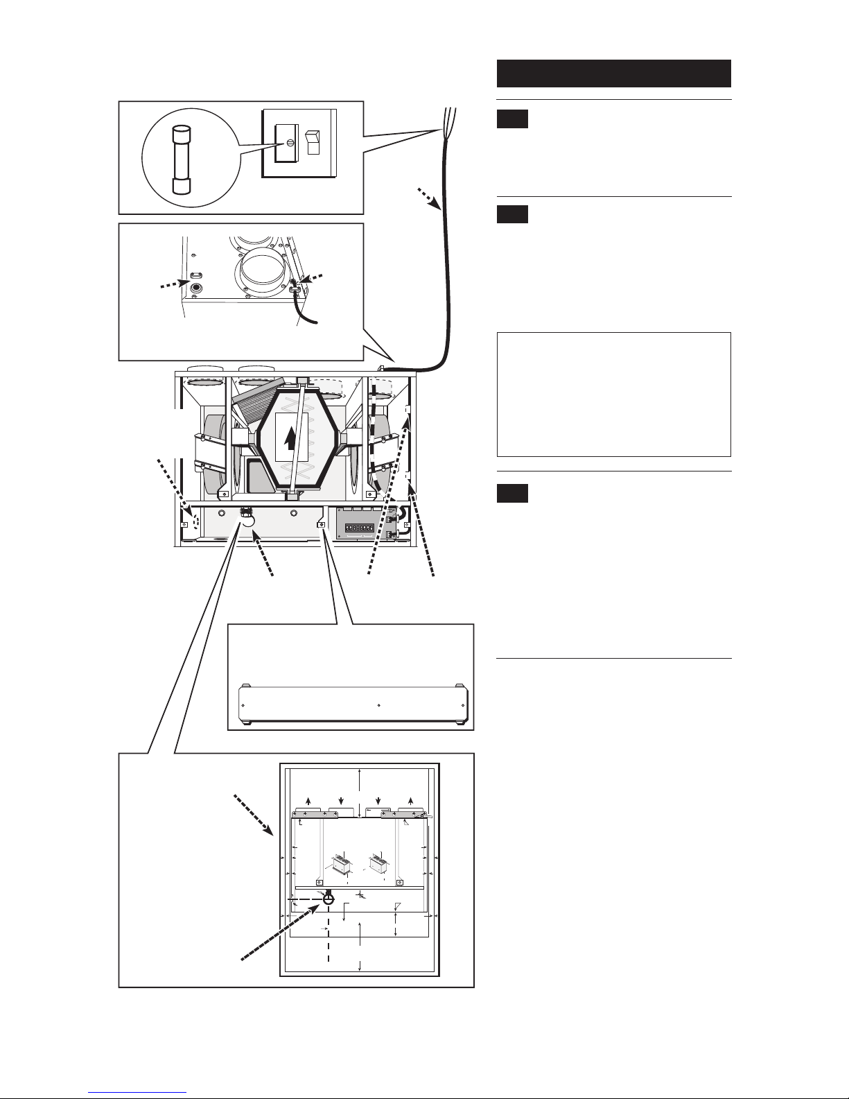
Remove bottom cover panel
to access the fan speed
settings & condensate connection.
The condensate
outlets
are marked
on the
wall template.
Wall template
Mains
lead
Cable
clamp &
grommet
for
mains
lead
Fuse
Fit fused double
pole isolator
Fit
3 Amp
fuse
Rear exit for
condensate
Cable clips for
accessories lead
FRONT
UP
Knock out
for side exit
condensate
Wall template HR204 &
HR205
(with cooker hood)
Whole House Ventilation System
Exhaust
Out
Fresh AirInHot Stale
Air In
Warm Air
Out
Minimum
Top
Clearance
200mm
Part No. 372706
98mm
Cooker Hood
Bottom of
MVHR Unit
Bottom of
Cooker Hood
Top of
MVHR
Unit
Bottom of
Mounting
Brackets
4 Fixing Holes
(Key Holes)
Use one
hole each side
Bottom
Fixing Hole
Back Case
Condensate Hole
Side Case Knock
Out Condensate Hole
Minimum Side
Clearance 1mm
Minimum Side
Clearance 1mm
Bottom Condensate
Pipe Exit (HR204 Only)
Minimum Bottom Clearance
100mm
(HR204 Model)
Minimum Side
Clearance
24mm
(HR205c)
Minimum Side
Clearance
5mm
(HR204)
MVHR
Side
Minimum Side
Clearance
24mm
(HR205c)
Minimum Side
Clearance
5mm
(HR204)
MVHR
Side
All dimensions
in mm
Minimum Top
Clearance
for servicing
200
Minimum
Side
Clearance
5
Minimum
Side
Clearance
5
Clearances
HR204
Minimum Bottom
Clearance
100
Minimum
Front
Clearance
for
servicing
250
280
Clearances
HR205
Minimum
Side
Clearance
(MVHR)
24
Minimum
Side
Clearance
(MVHR)
24
Minimum
Top Clearance
for servicing
200
300
Minimum
Front
Clearance
for servicing
250
Minimum Bottom
Clearance from Hob
700
Minimum
Side
Clearance
(C.Hood)
1
Measure Minimum
Bottom Clearance
700mm
From Hob
(HR205c Model)
Mains
Cable
Outlet
Top view of unit
Fig. 9
6.4 System controls
6.5 Electrical supply
1. External wiring must be correctly earthed ,
polarised and in accordance with the current
I.E.E. Regulations.
2. The mains supply must be 220-240V ~ 50Hz
fused at 3 Amps.
6.6 Condensate drain
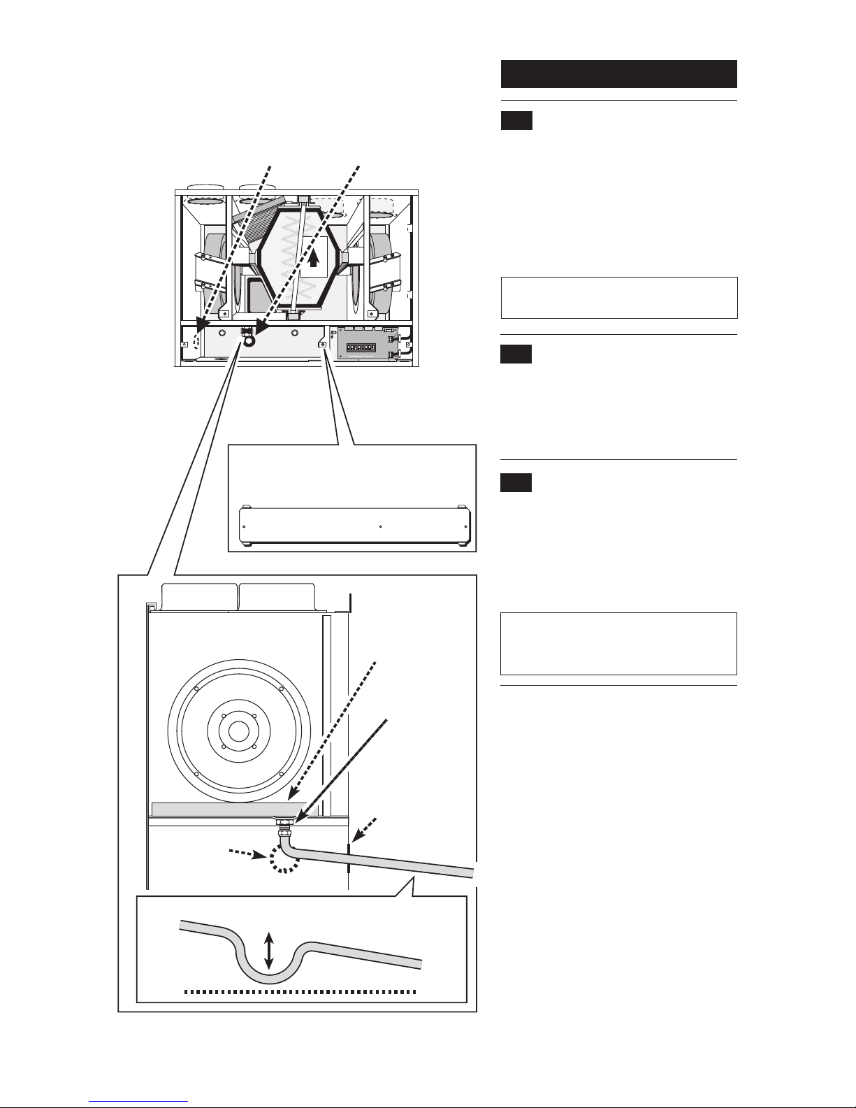
1. The condensate pipe should have a
continuous fall of 10° (1 in 6) with as much of the
condensate pipe as possible run inside the
property to avoid freezing. The pipe should also
incorporate a trap with a minimum height of
75mm or similar device to prevent a return of
foul air from the waste pipe. See Fig. .11
The LoWatt HR204 has three condensate outlet
positions; rear, bottom and left hand side.
Cable
clamp &
grommet
for
accessories
lead
See page 8 for a list of optional controls.
These are used to switch the LoWatt HR204
from normal speed to boost speed.
Note: The method of connection to the
mains supply must facilitate complete
electrical isolation of the appliance.
Connection may be via a fused double pole
isolator with a contact separation of at least
3mm in all poles and supplying the LoWatt
HR204 and its controls only. The LoWatt
HR204 is not designed to be fitted with a
plug.
Page 12
N
L
1
2
1 234
5
6
7
8
Normal
Boost
1 234
5
4
5
6
ON
FRONT
UP
12
E
x
h
a
u
s
t
O
u
t
F
r
es
h
A
ir
In
H
o
t
St
a
el
A
ir
In
W
a
rm
A
ir
O
u
t
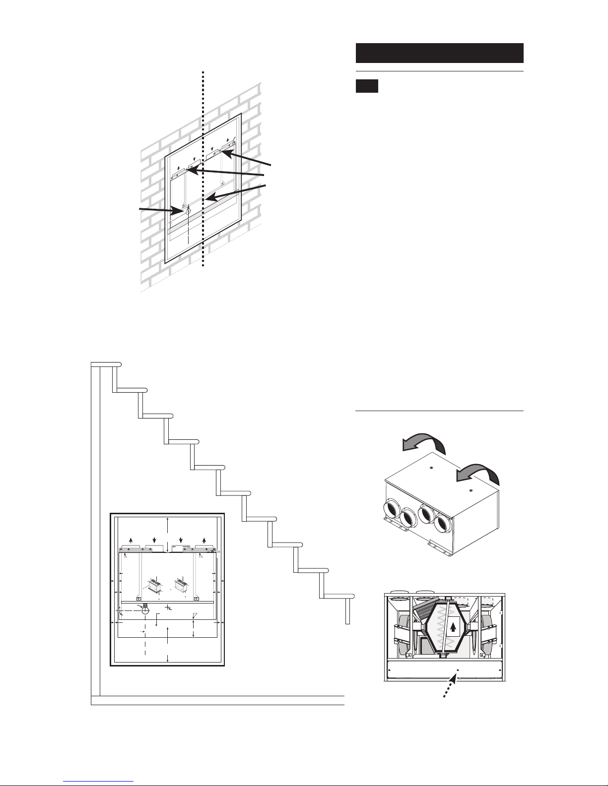
Example of a possible
understairs installation
Place unit on its back
& remove front cover
Remove electrical cover plate (3 screws)
Ground Floor
Stair Case
Mark position
of the
condensate
pipe. Ø15mm.
Drill where
required.
Mark position
of the
fixing holes.
2 top (minimum)
& 1 lower,
then drill & plug.
Wall templateHR204 &
HR205
(with cooker hood)
Whole House Ventilation System
Exhaust
Out
Fresh AirInHot Stale
Air In
Warm Air
Out
Minimum
Top
Clearance
200mm
Part No. 372706
98mm
Cooker Hood
Bottom of
MVHR Unit
Bottom of
Cooker Hood
Top of
MVHR
Unit
Bottom of
Mounting
Brackets
4 Fixing Holes
(Key Holes)
Use one
hole each side
Bottom
Fixing Hole
Back Case
Condensate Hole
Side Case Knock
Out Condensate Hole
Minimum Side
Clearance 1mm
Minimum Side
Clearance 1mm
Bottom Condensate
Pipe Exit (HR204 Only)
Minimum Bottom Clearance
100mm
(HR204 Model)
Minimum Side
Clearance
24mm
(HR205c)
Minimum Side
Clearance
5mm
(HR204)
MVHR
Side
Minimum Side
Clearance
24mm
(HR205c)
Minimum Side
Clearance
5mm
(HR204)
MVHR
Side
All dimensions
in mm
Minimum Top
Clearance
for servicing
200
Minimum
Side
Clearance
5
Minimum
Side
Clearance
5
Clearances
HR204
Minimum Bottom
Clearance
100
Minimum
Front
Clearance
for
servicing
250
280
Clearances
HR205c
Minimum
Side
Clearance
(MVHR)
24
Minimum
Side
Clearance
(MVHR)
24
Minimum
Top Clearance
for servicing
200
300
Minimum
Front
Clearance
for servicing
250
Minimum Bottom
Clearance from Hob
700
Minimum
Side
Clearance
(C.Hood)
1
Measure Minimum
Bottom Clearance
700mm
From Hob
(HR205c Model)
Mains
Cable
Outlet
7.0 Installation
7.1 Preparation
1. Check site requirements (Section 6) before
commencing.
2. Remove the fixing template from the carton.
3. After considering the site requirements,
position the template on the wall ensuring it is
4. Mark the positions of at least two top fixing
holes, the lower fixing hole and the condensate
outlet.
5. If required, mark off the positions of the four
duct connections.
6. Drill and plug the wall at the fixing points and
drill the condensate hole.
7. The top two screws should now be fitted
leaving enough space for the keyhole fixing slots
to engage.
6. Place the unit on its back (Fig.10). Release the
two screws from the front cover and remove it.
7. Remove the bottom electrical cover plate by
releasing the 3 screws, pulling the panel
forwards and disconnecting the earth lead to the
panel.
Fig. 10
Make sure the wall
template is level
level.
Mark out the position
of the unit with the
wall template.
Page 13
N
L
1
2
1 234
5
6
7
8
Normal
Boost
1 234
5
4
5
6
ON
FRONT
UP
13
7.3 Fitting the LoWatt HR204
1. Offer the unit to the wall and engage the
keyhole slots over the screws previously fitted.
2. Make sure the unit is level and tighten the top
screws before engaging the final screw.
7.4 Making the condensate connection
1. The condensate connector is suitable for
Ø15 mm pipe.
2. The condensate pipe should incorporate a
water trap or similar to prevent foul air being
drawn into the unit. The minimum height of a
trap should be 75 mm.
Note: To ensure the condensate pipe is
primed, slowly pour water into the
condensate tray until it discharges into
the drain.
Fig. 11
Remove bottom cover panel
to access the fan speed
settings & condensate connection.
Condensate
rear exit shown
Side View
Front Rear
Condensate
drain (15mm)
Rear exit for
condensate pipe
(with grommet)
Condensate tray
Knock out
for side exit
condensate
Rear exit for
condensate
(with grommet).
Knock out for
side exit
condensate.
10º fall (1 in 6)
Condensate
pipe (15mm)
A Trap must be fitted
75mm min height
7.0 Installation
7.2
Condensate outlet
1. If the condensate pipe is to exit the unit at the
left hand side, stand the unit up on its base.
2. Locate the semi-pierced hole and carefully
remove the metal disc.
3. Swap over the grommet used on the rear exit
hole and seal the rear hole with duct tape or
similar.
Note: The LoWatt HR204 has an extra
condensate outlet on the bottom panel.
Page 14
N
L
1
2
1 234
5
6
7
8
Normal
Boost
1 234
5
4
5
6
ON
FRONT
UP
14
7.0 Installation
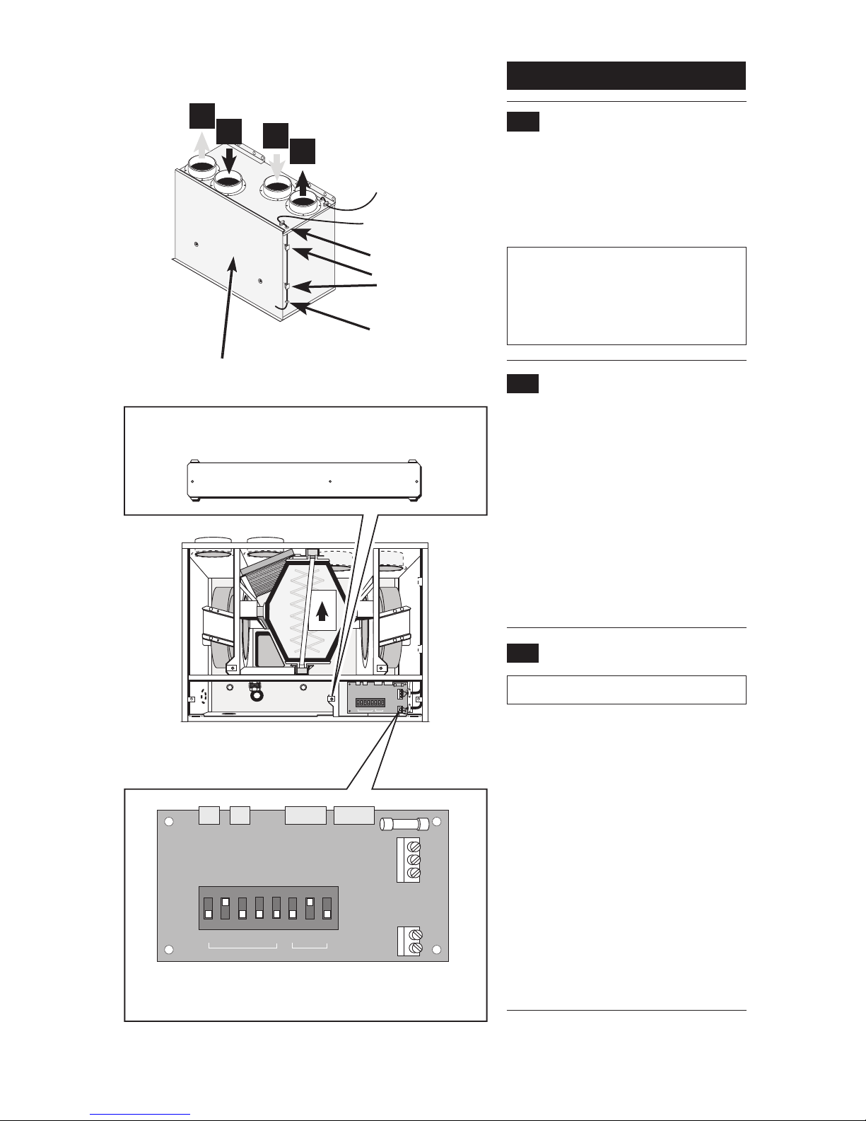
7.5 Making the duct connections
1. The unit has four duct connections suitable for
100mm round ducting.
1. Exhaust outlet to outside
2. Air inlet from outside
3. Stale air inlet from dwelling
4. Fresh air outlet to dwelling
Notes: It is essential that the duct system
is connected as indicated.
It is important that the duct system does
not interfere with the correct fitting of the
front cover and does not prevent the
correct operation of the unit.
7.6 Controls
1. The LoWatt HR204 requires external controls
to enable normal/boost switching. Otherwise it
will only run at its normal speed.
7.7 Making the electrical connection
Warning: This appliance must be earthed
Refit electrical cover plate.
Front cover
Fig. 12
1 2
3
4
5
6
7
8
N
L
1
2
Normal
Boost
1 2
3
4
5
4
5
6
ON
1. The unit must be set to the appropriate speed
as determined by air flow required and duct
system pressure (see page 7).
2. To change the speed settings of the fans,
change the position of the dip switches on the
PCB. The 5 switches on the left let you select
the normal speed from speeds 1 to 5. The
remaining 3 switches let you select the boost
speed from speeds 4 to 6.
3. Refit the electrical cover plate and its earth
lead.
4. Connect the flying lead to the mains supply see section 6.5.
5. Check the electrical installation for earth
continuity, short circuits, resistance to earth and
correct polarity.
Example shown
Normal speed = speed 2
Boost speed = speed 5
2. Drill a hole in the top grommet, (do not
slice), equal to half the diameter of the two
core cable to go through it.
3. Feed the lead into the unit through the top
grommet, down the side, through the lower
grommet and into the PCB area. Secure the
lead with the cable clips and clamps.
5. Wire to terminals 1 and 2. See wiring
diagrams in section 8.0.
Mains
lead
Optional
controls cable
Cable clips
on inside
1
2
3
4
Upper grommet
Lower grommet
Page 15
15
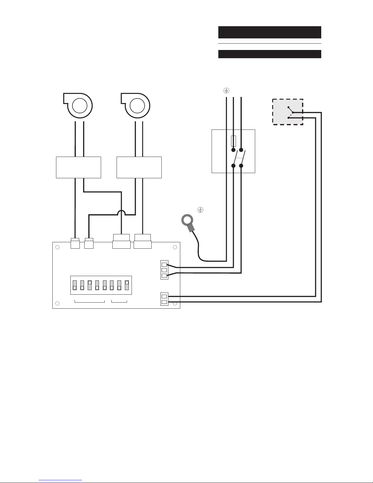
8.0 Wiring Diagrams
Fig. 13
LoWatt HR204 Wiring
Manual Normal /Boost
Switch NBSW or
Pull Switch PCSW
Common
Boost
Normal
L
Fan
(air out)
Fan
(air in)
SPEED SELECT
1
2
L
N
1 2
3
4
5
6
7
8
Normal
Boost
1 2
3
4
5
4
5
6
ON
MOTOR
CONTROL
A B
MOTOR
SUPPLY
A B
220-240V 50Hz
MOTOR B
CONTROL P.C.B
MOTOR A
CONTROL P.C.B
CHASSIS
3A
N
Page 16
L
Fan
(air out)
Fan
(air in)
SPEED SELECT
1
2
L
N
1 2
3
4
5
6
7
8
Normal
Boost
1 2
3
4
5
4
5
6
ON
MOTOR
CONTROL
A B
MOTOR
SUPPLY
A B
220-240V 50Hz
MOTOR B
CONTROL P.C.B
MOTOR A
CONTROL P.C.B
CHASSIS
N
16
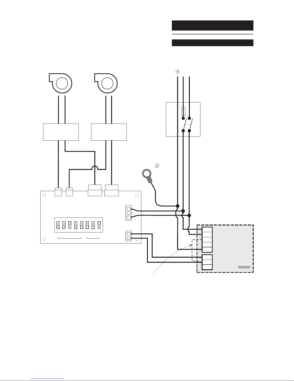
8.0 Wiring Diagrams
Fig. 14
LoWatt HR204 Wiring & CMSM controller
CMSM Controller
L
N
L
Live in
Neutral in
Live to relay
N
E
Neutral out
Earth
N.O
C
N.C
Live out to fan
Live out
Common
Important: Remove
live link in wire
S1 S2
3A
Page 17
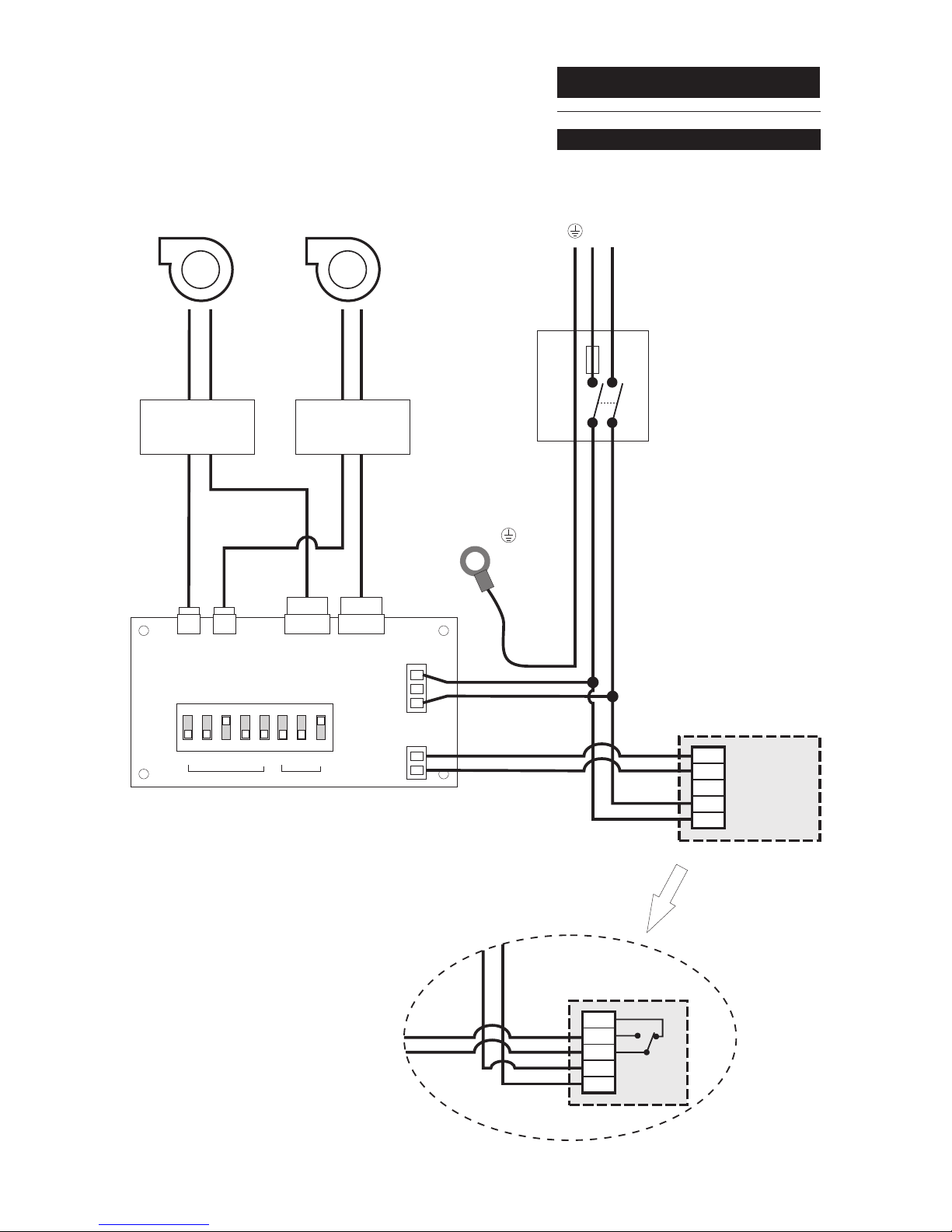
17
HS6 Humidistat
0
2
1
Common
Boost
Ordinary
N
L
LoWatt HR204 with optional humidistats
8.0 Wiring Diagrams
1
2
Fig. 15
L
Fan
(air out)
Fan
(air in)
SPEED SELECT
1
2
L
N
1 2
3
4
5
6
7
8
Normal
Boost
1 2
3
4
5
4
5
6
ON
MOTOR
CONTROL
A B
MOTOR
SUPPLY
A B
220-240V 50Hz
MOTOR B
CONTROL P.C.B
MOTOR A
CONTROL P.C.B
CHASSIS
N
Ecotronic Humidistat
5
4
3
L
N
1
2
L N
Alternative
humidistat
3A
Page 18
18
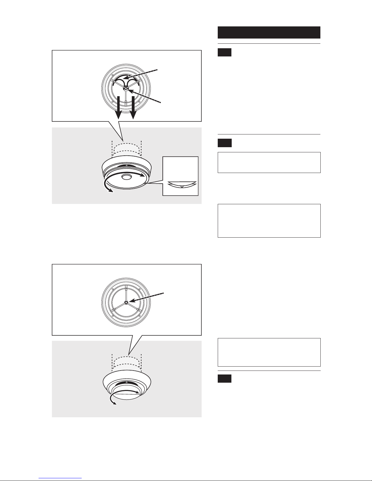
9.2 Balancing the system
It is important that a suitable anemometer
is used to balance the system to give the
required ventilation rates to each room.
1. Set the appliance running on normal speed.
2. Make a preliminary adjustment of all the duct
inlet and outlet louvres.
Note: The supply air terminal is directional
and incorporates a deflector plate. Ensure
that the deflector plate is correctly
positioned so that the active part of the
terminal is discharging to the room.
3. Check the flow rate and adjust if necessary
the extract valve furthest from the appliance.
4. Check the flow rates and adjust if necessary
the remaining extract valves.
5. Repeat the flow checks and adjust until the
extract system is balanced.
6. Check the flow rate and adjust if necessary
the inlet valve furthest from the appliance.
7. Check the flow rate and adjust if necessary
the remaining inlet valves.
8. Repeat the checks and adjust until the system
is correctly balanced.
Note: If the flow rates have been achieved
with all the louvres nearly closed, it may
be possible to reduce the fan speed and
re-adjust the louvre settings.
9.3 Instruct the user
Instruct the user in the operation of the
appliance. Hand over these instructions, giving
advice on the necessity for regular servicing of
the filters and heat exchanger.
SV100
Adjust ceiling supply valve for living room etc.
EV100
Adjust ceiling extract valve for bathroom etc
Inside view of
extract valve
Locking nut
to lock
the valve
in position
Inside view of
supply valve
Locking nut
to lock
the valve
in position
Air direction
Air deflector
plate
Air
direction
indicator
Fig. 16
9.0 Commissioning
9.1
Prepare for commissioning
1. Refit the front cover by hooking it over the
top lip of the appliance and swinging down.
Tighten the two case screws.
2. Check the external controls are set to normal
running.
3. Turn on the electrical supply. The unit will now
start running at the normal ventilation speed.
4. Set the external control to boost. The unit will
now switch to boost speed.
Page 19
N
L
1
2
1 234
5
6
7
8
Normal
Boost
1 234
5
4
5
6
ON
FRONT
UP
WiringService
19
10.0 Maintenance
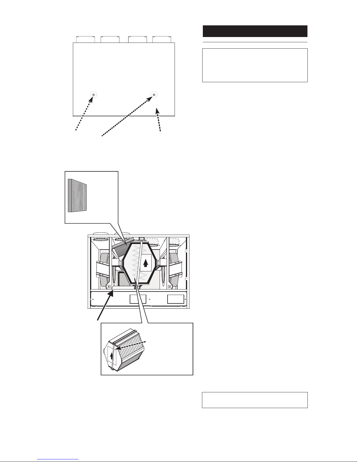
Important: Before servicing ensure that the
appliance is isolated from the electrical
supply. After isolating from the electrical
supply, allow one minute for the fans to stop
rotating before servicing the appliance.
1. Lift off the front cover by releasing the two
screws and lifting upwards.
2. Remove the air inlet filter by pulling forwards.
3. Taking note of the offset sliders, carefully remove
the heat exchanger by gently pulling forwards.
4. Check both fans and fan compartments for
deposits. Clean as necessary, making sure that you
5. Remove the condensate tray by pulling forwards.
Check and clean if necessary.
6. Check the condition of the four heat exchanger
sealing strips and front cover seal. Replace seals as
necessary.
Note: Ensure the heat exchanger is located
correctly in the offset sliders.
Pull forward & remove
the cover.
Remove screws
Pull out & clean the
Condensate Tray
Air inlet
filter. Pull
out, brush
& vacuum
clean.
11. Re-assemble in reverse order and re-fit the
front cover ensuring it makes a good seal.
Fig. 17
The following cleaning and disinfection routine
should be conducted every 6 months to maintain
the efficiency and hygiene of the unit. It should be
carried out by a suitably qualified person.
Care should be taken when using sterilising
solutions. Gloves and eye protection are the
minimum levels of personal protective equipment
required. Do not spill the cleaning solution on any
other surfaces, especially fabric as bleaching
damage could occur.
The sterilising solution used should be a 'Milton'
type solution diluted 1 to 20, or 'Instachlor PR1000'
tablets (or similar), these will then give a 1,000
ppm available Chlorine solution.
7. Carefully wash the heat exchanger, making sure
that the solution penetrates the cell plates. Take
care not to loosen the plates. Dry thoroughly before
refitting.
8.Drain and clean the condensate pipe using a
bottlebrush, or similar, soaked in the sterilising
solution.
9. Wipe down all parts showing signs of fungal /
mould growth with the sterilising solution.
10. All parts should be well rinsed with clean water
and dried after cleaning.
F
R N
T
O
U
P
Use strap to pull
out heat
exchanger.
12. Check the condition of the ductwork system,
the soundness of all joints and repair if necessary.
Carefully vacuum the filter. Replace if necessary.
do not disturb any cables or connections.
Page 20
N
L
1
2
1 234
5
6
7
8
Normal
Boost
1 234
5
4
5
6
ON
FRONT
UP
N
L
1
2
1 234
5
6
7
8
Normal
Boost
1 234
5
4
5
6
ON
20
11.0 Changing Components
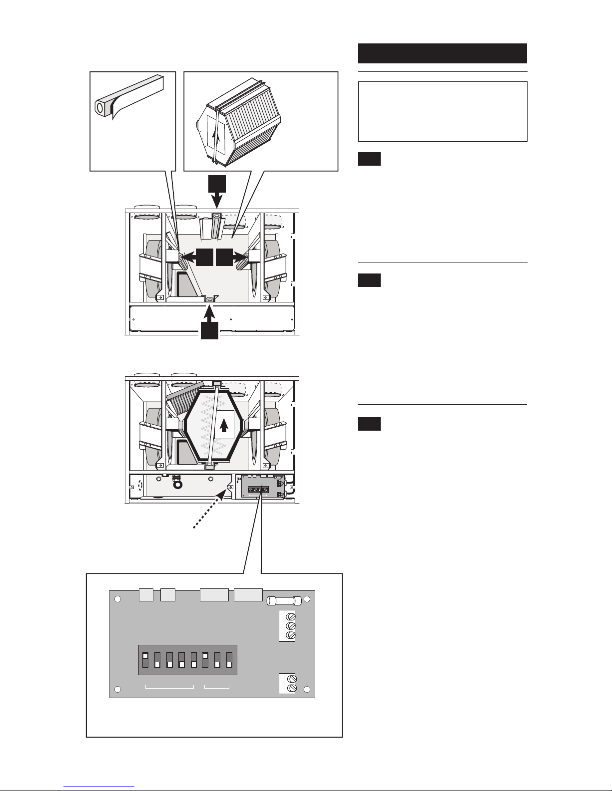
11.3 Speed select & motor control PCBs
1. Remove the front cover by releasing the two
screws and lifting the cover up and forwards.
2. Remove the bottom electrical cover plate by
releasing the 3 screws, pulling the plate
forwards and disconnecting the earth lead to the
it. Make a note of the speed settings of the
dip switch and the wiring arrangement for the
PCBs.
3. Remove the two screw securing the PCB
chassis to the bulkhead. Pull the chassis
forward and down.
7. Re-assemble in reverse order. Make sure rear
tab of PCB chassis locates in slot. Check the
installation for earth continuity, short circuits,
resistance to earth and correct polarity.
IMPORTANT: ISOLATE FROM THE
ELECTRICAL SUPPLY BEFORE STARTING
ANY WORK ON THE APPLIANCE.
Fig. 18
4. Make a note of the connections between
PCBs and motors.
5. Disconnect the motor cables, mains cable
and boost switch cable. Remove chassis and
PCBs completely.
6. Replace PCBs as necessary.
Remove electrical cover plate.
Example shown
Normal speed = speed 1
Boost speed = speed 4
11.1 Heat exchanger
1. Lift off the front cover by releasing the two
screws and lifting upwards.
2. Gently remove the heat exchanger by pulling
the strap forwards.
3. Re-assemble in reverse order taking care not
to damage the heat exchanger seals.
11.2 Heat exchanger seals
1. Remove the heat exchanger (see 11.1).
2. Remove the four heat exchanger seals taking
care to remove all the old adhesive backing.
3. Fit the new seals ensuring they make good
contact with the location channel.
4. Re-assemble in reverse order taking care not
to damage the heat exchanger seals.
F
R
O
N
T
U
P
Re-fit new
heat
exchanger
1 3
2
4
Fit 4 new
self-adhesive
sealing strips
(see positions
1 to 4 below)
Fig. 18
1 2
3
4
5
6
7
8
N
L
1
2
Normal
Boost
1 234
5
4
5
6
ON
THE FANS MAY CONTINUE TO ROTATE
FOR A MINUTE AFTERWARDS.
Page 21
21
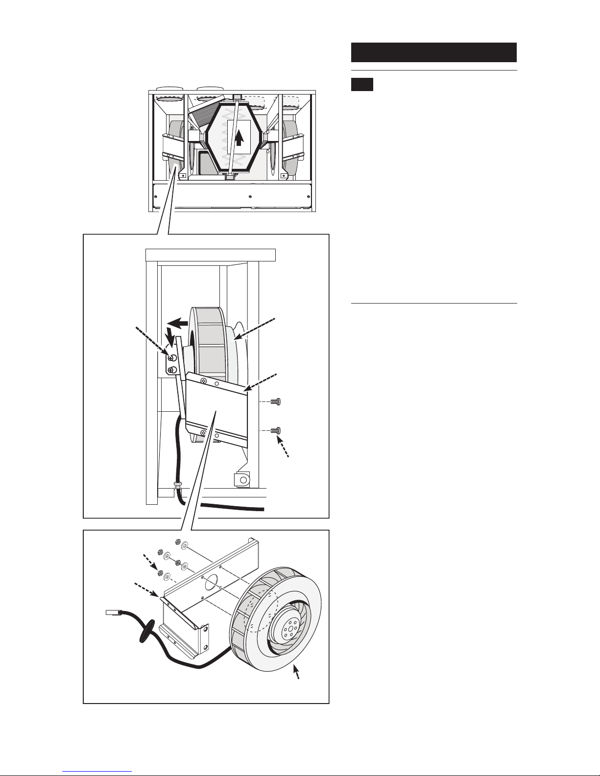
11.4 Extract fan and input fan
1. Lift off the front cover by releasing the two
screws and lifting upwards.
2. Remove the PCB chassis by following the
instructions in 11.3. Disconnect the motor lead.
3. Slacken the two rear fan bracket screws.
4. Remove the two front fan bracket screws and
remove the fan assembly.
Note the position of the fan bracket relative to
the fan.
5. Remove the bracket and re-fit to the new fan.
6. Re-assemble with the new fan in reverse
order ensuring the cable does not foul the fan
motor. Check the electrical installation for
earth continuity, short circuits, resistance to
earth and correct polarity.
11.0 Changing Components
Removal
of the
left hand
fan
(right hand
fan similiar)
FRONT
UP
Push fan
assenbly
to the left
and pull
away from
unit
Slacken
the 2 rear
securing
screws
Fan support
bracket
Fan support
bracket
Fan
Fan securing
nuts & washers
Remove
the 2 front
securing
screws
Fig. 19
Page 22
22
12.0 Fault Finding
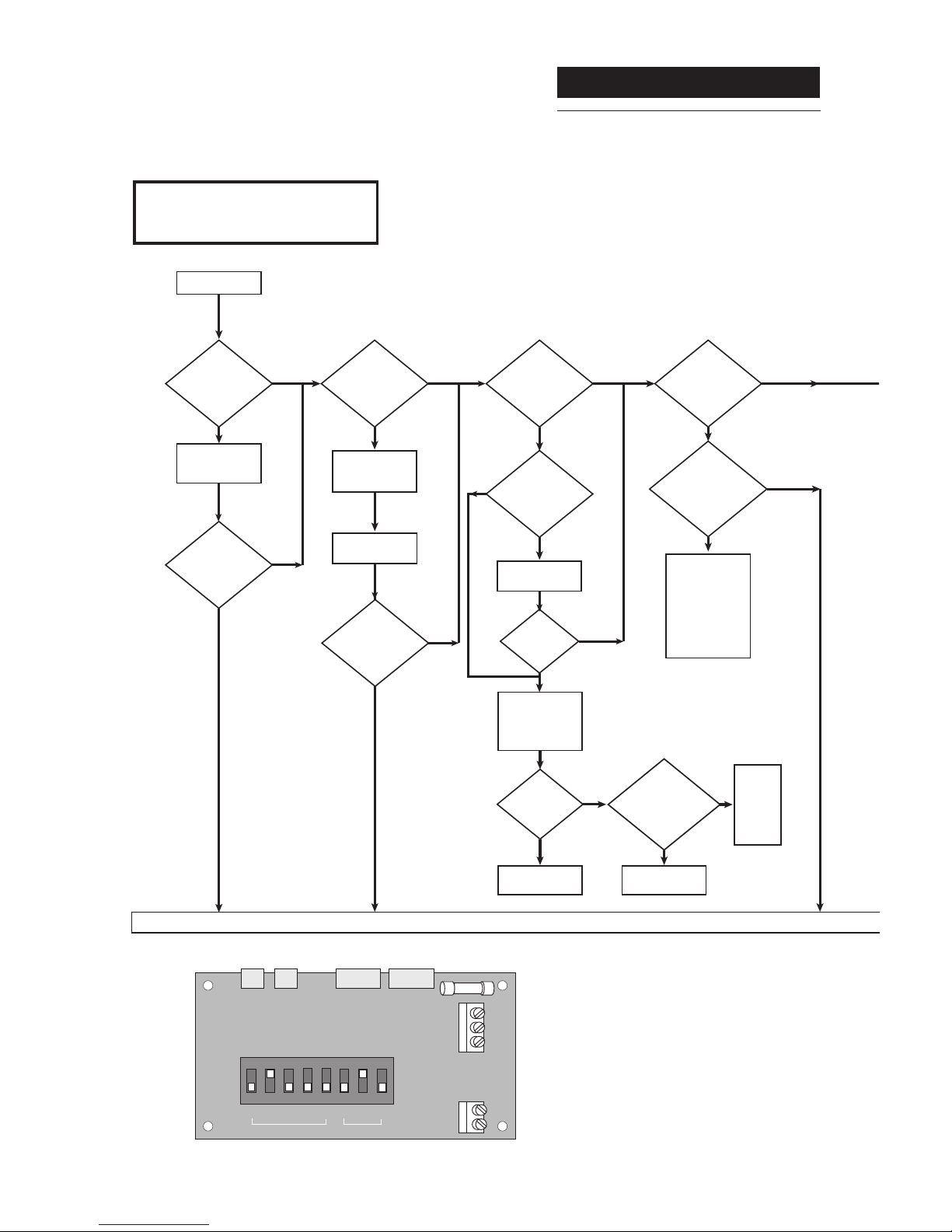
START
YES
NO
Check mains
supply.
Is there
mains voltage
across terminals
A1 & A2?
YES
NO
Investigate cause
and
rectify fault
Is the
fuse on the
speed select PCB
O.K?
Replace speed
NO
Is there low
voltage between
B1 and B2?
YES
NO
Check external
control wiring.
Reconnect wires
to terminals
B1 & B2.
Replace external
controls
Check
external
control,
rectify or
replace
as
necessary.
NO
Do the
external controls
have/require a mains
supply?
Are both fans
operating?
YES YES
Replace fuse
Before starting FAULT FINDING
carry out preliminary electrical systems checks
i.e. Earth Continuity, Polarity, Short Circuit
and Resistance to Earth.
Ensure all external controls are operating
and are set to normal running. Ensure that
a mains electrical supply is available to the
unit.
Refer to diagrams below to
identify terminals on components
(e.g. A1, B2 etc).
FINISH
NO
YES
Did this solve
the problem?
NO
YES
Did this solve
the problem?
YES
NO
NO
Clean filter &
heat exchanger
(section 10). Check
duct system and
terminals for
blockages or
damage. Ensure
terminals are
adjusted correctly.
Is there
adequate airflow
at the appliance
inlets and
outlets
Do external
controls switch
the unit to boost?
NO
Correct speed
settings
Is the
boost speed set
higher than the normal
speed on dip
switch C?
NO
YES
Did this solve
the problem?
YES
A2
A1
B2
B1
C
FUSE
SPEED SELECT PCB
YES
Fig. 20
1 2
3
4
5
6
7
8
N
L
1
2
Normal
Boost
1 234
5
4
5
6
ON
select PCB.
Page 23
23
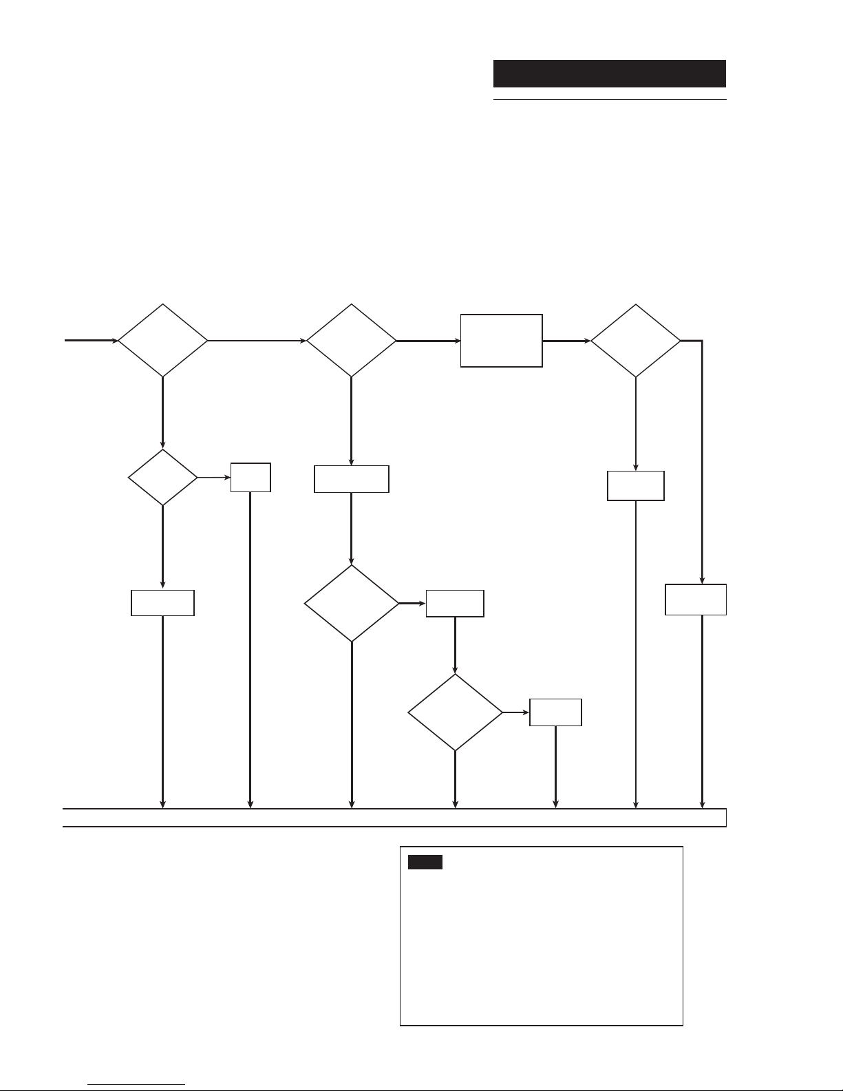
Replace fan
(section 11.4)
YES
Re-align
fan
either fan rotate
when powered?
Replace speed
select PCB.
NO
NO
NO
Are fans
free to
rotate?
Is the
fan fouling
on inlet
ring?
YES
Note
NO
YES
Did this solve
the problem?
YES
Does
Swap the problem
fan's connection to
the drive PCB with
the other fan's drive
PCB.
YES
NO
Does the
same fan fail to
run?
Replace
Replace problem
drive PCB
Replace fan
drive PCBs.
NO
YES
Did this solve
the problem?
Replace fans
FINISH
If the either fan does not rotate, check the entire
system and unit for correct installation. Check all
ducting outside and terminals for blockages.
The drive PCB can sense if the fan is not rotating.
When this happens, it will shut off the power to the
motor to prevent overheating. It will try powering the
motor again every few seconds until the problem is
resolved. This is characterised by the impeller jerking
every few seconds.
problem fan
12.0 Fault Finding
Page 24
24
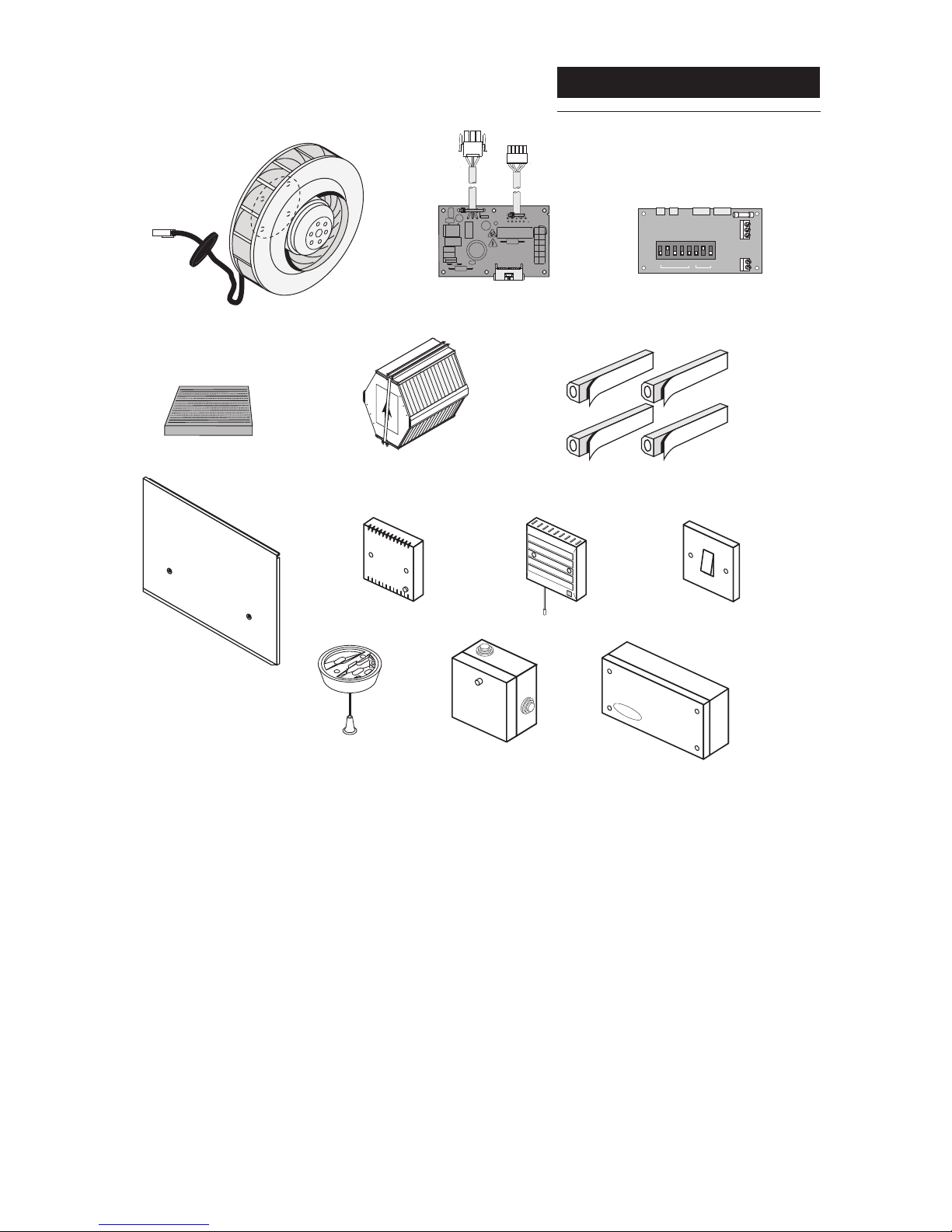
13.0 Short Parts List
1 2
3
4
5
6
10
7
8
12
N
rmo
a
l
B
o
ost
11
FR
O T
N
U
P
Fig. 21
Key No. Spares Part No. Description
1 436373 DC motor/impeller assembly
436374 Motor Drive PCB
372735 Inlet duct filter
372736 Heat exchanger
372737 Heat exchanger seals (4 off)
372739 Outer door/cover assembly
Optional extras
370254 Humidity sensor HS6
370495 Normal/boost switch NBSW
370278 Normal/boost pull cord switch PCSW
2
3
4
5
6
7
8
9
10
11
12
13
436375 Speed Select PCB
7
6
5
4
3
2
1
NLE
TAC
N/A
PWM
0 v
+V
370346
435960
TIM2 timer
CMSM controller
13
436224B - 0807
1 234
5
6
7
8
N
L
1
2
Normal
Boost
1 234
5
4
5
6
ON
9
563532 Ecotronic humidity sensor
 Loading...