

Page 1
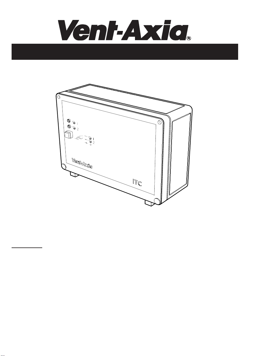
TWIN FAN CONTROLLER
Installation and Wiring Instructions
Models:- ITC and ITC-DS
Maximum load : 220-240V 50Hz ~ 9A and 380-415V 50Hz 3 ~ 9A
IMPORTANT - READ THESE INSTRUCTIONS FULL Y BEFORE COMMENCING INSTALLA TION.
1. Ensure that the mains supply voltage, frequency, number of phases and power rating comply with the
details on the rating label. Check that the controller can cope with the load (including starting current).
2. All wiring must be in accordance with current I.E.E. wiring regulations (BS7671), or the appropriate
standards in your country. The equipment should be provided with a local all pole isolator switch having a
contact separation of at least 3mm. We recommend that wiring to the equipment be made in conduit for
added protection.
3. This equipment must be earthed.
4. Ensure safety regulations and practices are adhered to when installing and using this equipment.
5. The controller must not be used where it is liable to be subjected to water spray from hoses, etc., or where
the ambient air temperatures may exceed 40°C.
6. When the fan motor thermal protector terminals (TK or TP) are brought out externally, they MUST be
connected to the relevant controller terminals.
Page 2

FOREWORD
The Vent Axia twin fan controller range comprise of the following modules;
1. ITC Basic twin fan controller.
2. ITC-DS Twin fan controller with 12/24 hr duty sharing.
3. RVC Remote visual controller
4. RSC Remote setback controller
Both the ITC and ITC-DS controllers have the following features;
a. control both single and three phase fans if thermal overloads are fitted to the motors.
b. fan failure indication to Building Management System (BMS) via voltage-free contacts.
c. connection to external sensors (sensors must have voltage-free contacts).
d. fan can be speed controlled using only one speed controller.
The RVC module is used to indicate the status and to select the operation of the fans remotely (up to 100m
away). Connections to the ITC and ITC-DS are Extra Low Voltage data link.
The RSC is used to change the power supply to the fans (eg. switching between the mains supply and a speed
controller). The selection of power supply can be achieved by any sensors or timers with voltage-free contacts.
Connections between the RSC and the sensor are Extra Low Voltage. Contact your local Vent-Axia distributor
for a full list of compatible sensors.
MOUNTING
1. Install the controller in a ventilated area.
ITC and ITC-DS can be fitted locally to the fans to reduced wiring cost and are rated to IP44. In this setup, RVC
should be be used to indicate the status of the system at a remote location.
2. If the controller is mounted on metal or other conductive surface; that surface MUST be earthed.
3. Open the lid to gain access to the fixing holes. Securely mount the controller to the surface using appropriate
fasteners. Route the supply and outlet cables through ‘knock-out’ holes in the casing.
OPERA TING ST ATUS
The ITC and ITC-DS has 2 LED's to indicate which fan is operating and a pushbutton to select either fan 1,
fan 2 or standby mode.
The relay contacts for BMS indications are used to indicate the following conditions:
contacts#1 contacts#2 system condition
closed closed system OK
opened closed fan 1 failed
closed opened fan 2 failed
opened opened both fans failed or power failure
FUSES
The electronic circuit is protected by a 20mm long 1A time-lag (type T) fuse.
The 24AC output is protected by a 20mm long 500mA time-lag (type T) fuse.
Page 3
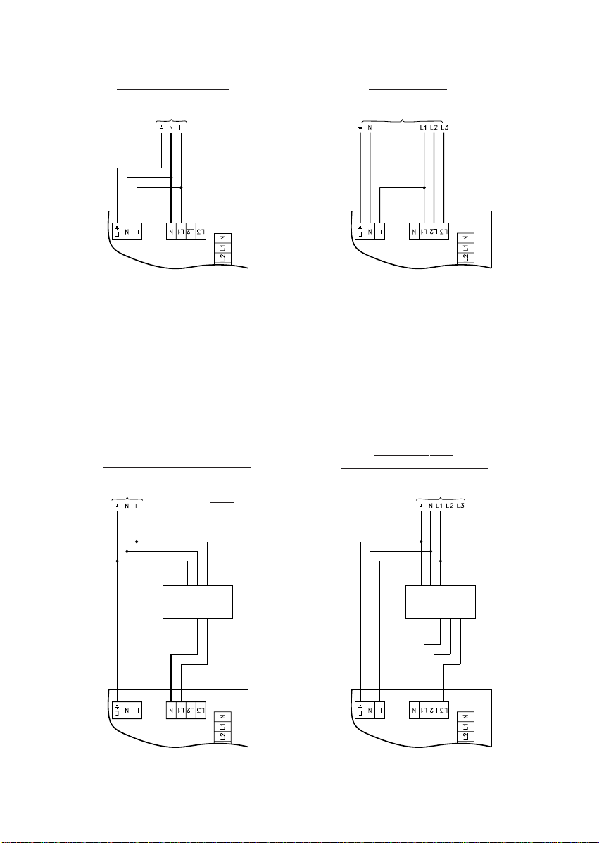
SUPPLY CONNECTIONS
SINGLE PHASE FANS
TO 220-240V ~ 50Hz SUPPLY
3 PHASE FANS
TO 380-415V 3~ 50Hz SUPPLY
SINGLE PHASE FANS
WITH SPEED CONTROLLER
TO 220-240V ~ 50Hz SUPPLY
NOTE: IF THE SPEED CONTROLLERS HAVE
TK OR TP TERMINALS, A LINK SHOULD BE
WIRED ACROSS THESE TERMINALS.
SPEED
CONTROLLER
3 PHASE FANS
WITH SPEED CONTROLLER
TO 380-415V 3~ 50Hz SUPPLY
SPEED
CONTROLLER
Page 4
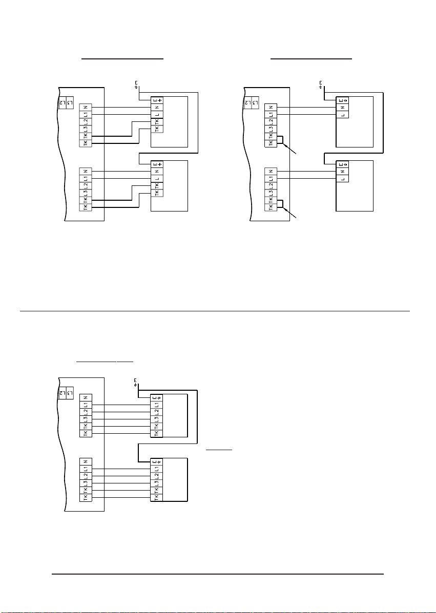
OUTLET CONNECTIONS
SINGLE PHASE FANS
FAN 2
FAN 1
SINGLE PHASE FANS
WITH INTERNALLY WIRED
THERMAL OVERLOAD PROTECTION.
FAN 2
LINK
WIRE
FAN 1
LINK
WIRE
3 PHASE FANS
FAN 2
NOTE: 3 PHASE FANS MUST HAVE EXTERNALLY
CONNECTED THERMAL OVERLOAD PROTECTION.
FAN 1
NOTE: INSTALLER MUST PROVIDE ADEQUATE EARTH BONDING TO THE FANS
Page 5
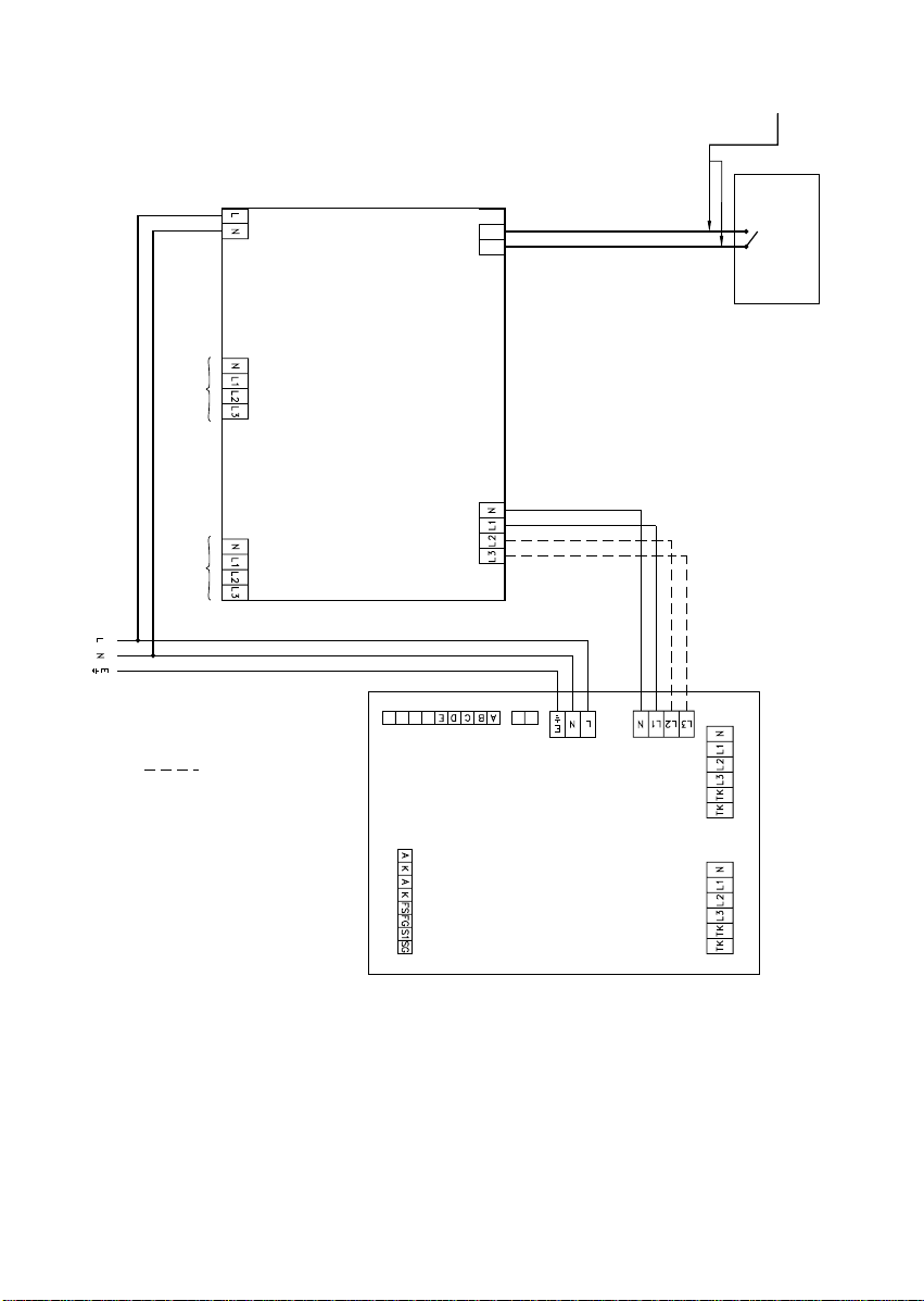
RSC CONNECTIONS
POWER SUPPLY
No. 1.
POWER SUPPLY
No. 2.
220-240V ~ SUPPLY
240V
INPUT 1
INPUT 2
RSC
(10314230A)
+Ve -Ve
OUTPUT
EXTRA LOW VOLTAGE
WIRING
SELECTOR SWITCH
ANY TIMER OR SENSOR
WITH VOLTAGE - FREE
CONTACTS
ONLY REQUIRED IF
USING 3 PHASE FANS
ITC
Page 6
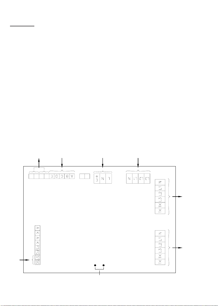
GENERAL WIRING
WARNING
- ISOLATE MAINS SUPPLY BEFORE MAKING CONNECTIONS
- THIS EQUIPMENT MUST BE EARTHED
1. All electrical connections should be made by a properly qualified electrician.
2. Wire the supply and outlet cables as shown in the wiring diagrams.
3. After making wiring connections, replace the lid onto the base and ensure the cable glands; gasket;
etc. are securely located.
NOTES ON RUNNING
Both the ITC and ITC-DS operates by detecting the current flowing to the fan. If it is necessary to
switch the fan on and off for any reason; e.g. fan off at night, this switching operation must be done
via the ITC or ITC-DS controller by making or breaking the contacts connected across S1 - SG. Otherwise a fan failure will be registered.
Before switching on CHECK:
1. All mountings are secure.
2. Circuit protection devices are fitted.
3. Earth connections have been made and are secure.
4. The fan is installed properly and the impeller is free to rotate.
5. All relevant guards are fitted.
LAYOUT OF CONNECTIONS
VOLTAGE-FREE
CONTACTS TO
BMS
REMOTE VISUAL
CONTROLLER
CONNECTIONS
SUPPLY FOR ITC
CONTROLLER
SUPPLY
FOR FANS
SENSOR
CONNECTIONS
FAN 2
FAIL
FAN 1
REMOTE
FAIL
LED 1
LED 2
LINK TO SELECT 24HR. CHANGE OVER. MODEL ITC-DS ONLY IS INSERTED HERE
(12HR. IS SELECTED WITHOUT THE LINK IN PLACE)
24V AC
OUTPUT
TO FAN 2
OUTPUT
TO FAN 1
Page 7
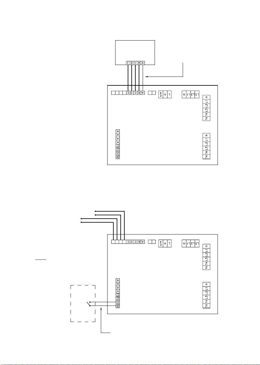
RVC CONNECTIONS
RVC
FAN
FAN
REMOTE.
FAIL
FAIL
2
1
LED 1
LED 2
SENSOR CONNECTIONS AND BMS CONNECTIONS
TO BMS FAN 1 STATUS (CONTACTS #1)
TO BMS FAN 2 STATUS
(CONTACTS #2)
EXTRA LOW VOLTAGE WIRING
UP TO 100M LONG.
24V AC
NOTE: IF A SENSOR IS NOT USED
A LINK MUST BE WIRED ACROSS
S1 - SG. (FACTORY PREWIRED).
SENSOR WITH
VOLTAGE - FREE
CONTACTS
FAN
FAN
REMOTE. 24V AC
FAIL
FAIL
1
2
LED 2LED 1
EXTRA LOW VOLTAGE WIRING UP TO 25M LONG
 Loading...