

Page 1
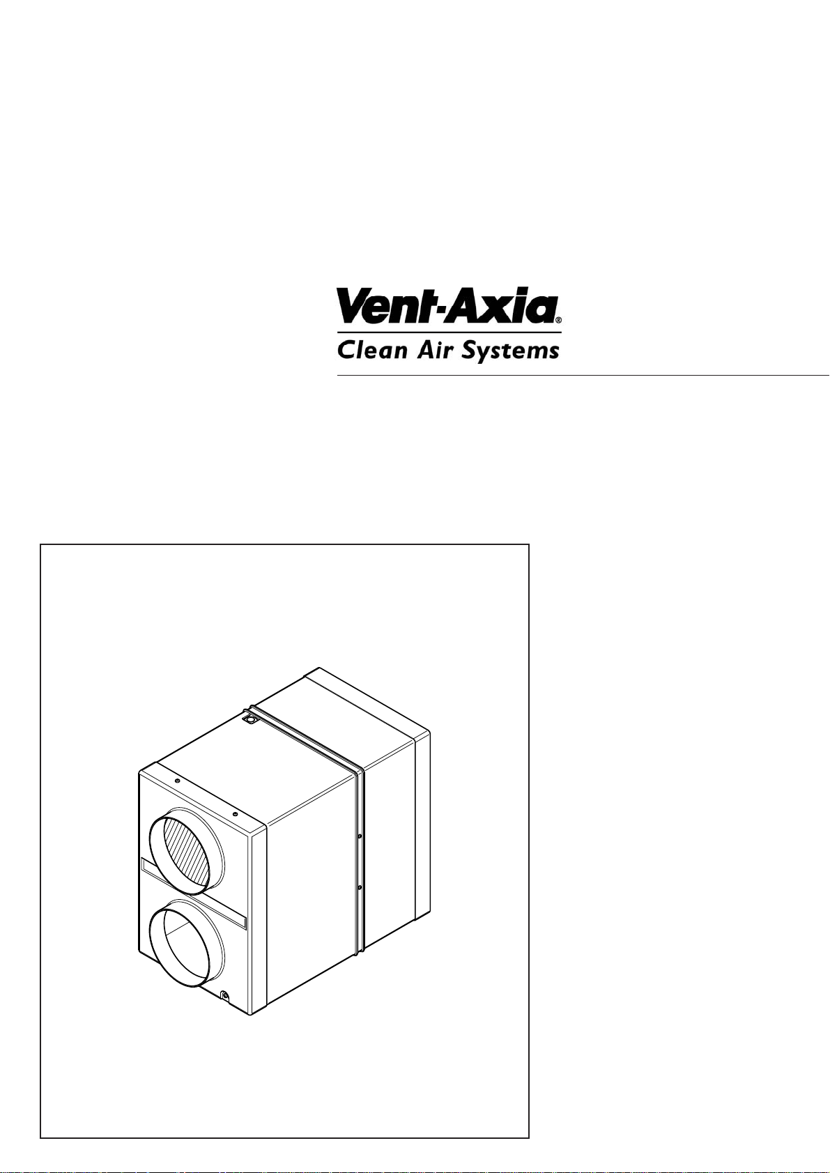
HR300RW6
Semi-Remote Wall Mounted
Heat Recovery Ventilator
Installation and
Servicing Instructions
Please leave these instructions with the user
Page 2

2
Page 3
3
1.0 Introduction 4
2.0 Site Requirements 5
3.0 Installation 6
4.0 Electrical 8
5.0 Maintenance 9
Section Page
Contents
Page 4
1.0 Introduction
4
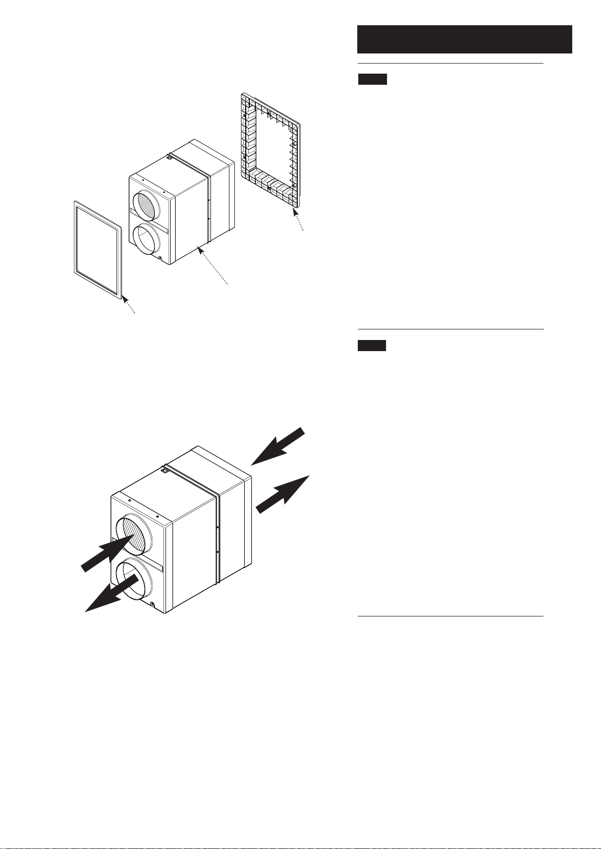
1.1 Description (Figs. 1 & 2)
1. The HR300RW6 unit is a semi-remote wall
mounted heat recovery ventilator which is ideal
for light commercial applications including
function rooms, swimming pools, offices,
classrooms etc.
2. The HR300RW6 comes complete with two
internal rotor motors and two mixed flow fans.
3. The maximum power consumption for the unit
is 100w.
4. The mixed flow fans and heat exchanger
arrangement simultaneously supplies and
extracts air while transferring heat from the stale
exhaust airflow to the fresh intake airflow. This
provides up to 70% heat recovery from the stale
extracted air.
1.2 Ancillary Equipment
1. The HR300RW6 unit can be used in conjunction
with a range of ancillary equipment.
Controller: A range of controllers - see section
3.1 Controllers.
PFD150: PVC flexible ducting - 6 metre length.
AFD150: Aluminium flexible ducting - 10 metre
length.
IFD150: Insulated flexible ducting - 6 metre
length.
AV150: Circular adjustable air valve with spigot
assembly. Suitable for extraction and supply.
ESG150: Square louvre grille with removable
core and washable filter. Suitable for extraction
and supply.
Stale Air from
Wet Rooms
Fresh Warmed Air
to Dry Rooms
Fresh Air
from Outside
Stale Air
Exhaust
Fig. 1
Fig. 2
Panel Flange
Bezel
HR300RW6
Page 5
2.0 Site Requirement
5
2.1 Information
1. The unit is designed for installation in external
walls with a thickness of between 150mm to
315mm.
2. The unit must be sited and connected by a
suitably qualified person and be in accordance
with current UK Building Regulations and I.E.E.
Wiring Regulations (BS 7671).
3. The unit is intended for permanent connection
to the mains electrical supply.
4. The unit is intended for fixed wiring installation.
5. Wiring to the unit in the UK must be via a
switched fused spur. The switched fused spur
must have a 3mm minimum contact gap in all
poles.
6. Ensure that the mains electrical supply is
compatible with the rating label attached to the
product.
7. The unit must be sited such that the ambient
temperature will not exceed 40° C.
8. Do not site the appliance in the vicinity of
excessive levels of airborne oil or grease.
9. If the unit is installed in a room containing a
fuel burning appliance, the installer must ensure
that air replacement is adequate for both
appliances.
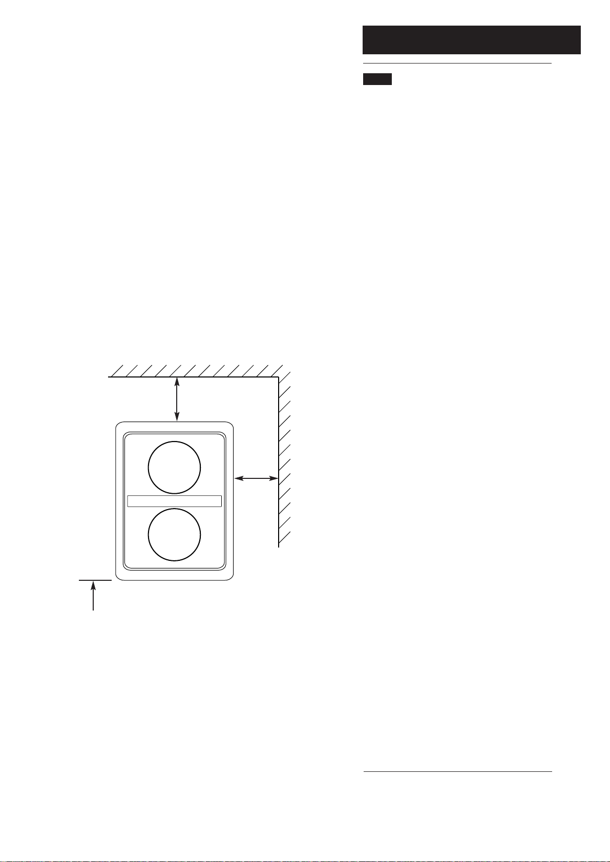
10. The unit must not be installed at a level below
500mm from the floor.
11. The internal grille surround must be sited at
least 125mm away from any wall or projecting
surface (Fig. 3).
12. The external grille of the unit must be sited at
least 600mm away from any flue of gas or solid
fuel appliances. This is to avoid back flow of
gases entering the room.
13. All safety regulations and requirements must
be strictly followed to prevent hazards to life and
property both during and after installation and
during subsequent maintenance or servicing.
14. Ensure the mains electrical supply is switched
off before commencing installation or
maintenance.
Fig. 3
125mm
Min
125mm
Min
500mm Min Above
Floor Level
Page 6
3.0 Installation
6
3.1 Controllers
1. The HR300RW6 unit can be installed in
conjunction with a number of controllers.
VCON6: The VCON6 controller can be used to
provide Off/Low/Normal/Boost/Sensor control.
(The HS6 humidistat or TIM2 over-run timer can
be used in conjunction with the VCON6 controller
to provide automatic control.
VCON5: The VCON5 controller can be used to
provide variable speed control.
HS6: The HS6 is a humidity sensor for switching
between HIGH and LOW speeds during the
daytime according to relative humidity levels.
TIM2: The TIM2 is an overrun timer which can
also be used to control the HR100 unit via a light
switch or remote sensor e.g. PIR detector.
3.2 Initial Preparation
1. Select an approved electrical control
arrangement for the HR300RW6 unit (above).
2. After considering the site requirements
(Section 2.0), select a suitable site for the unit
and controllers and work out the cable runs.
WARNING: Before deciding on the final position
for the unit, check there are no buried cables,
pipes or obstructions on the outside wall.
Cable requirements: Suitably (Basec or Har)
approved three core cable of appropriate current
carrying capacity.
3. Install the cable runs and appropriate
controllers in conjunction with a fused connection
unit. Contact gap must not be less than 3mm.
4. Choose suitable locations and install internal
louvre grilles into desired locations.
5. Connect ducting to louvre grilles and run to the
desired location of unit.
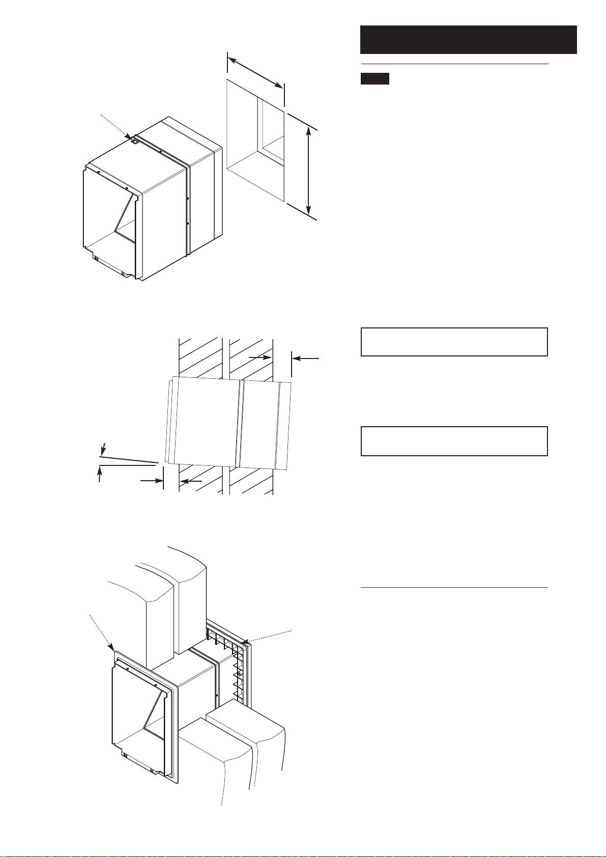
4. Working from the inside, mark out the
position of the mounting hole - 280mm wide x
380mm high (see Fixing Template).
5. Carefully cut the holes in the inner and outer
brick courses to form a suitable aperture to
receive the unit. Ensure that this is level.
NOTE: Bricks will cut more easily and
accurately if a series of holes are drilled close
together along the marked lines.
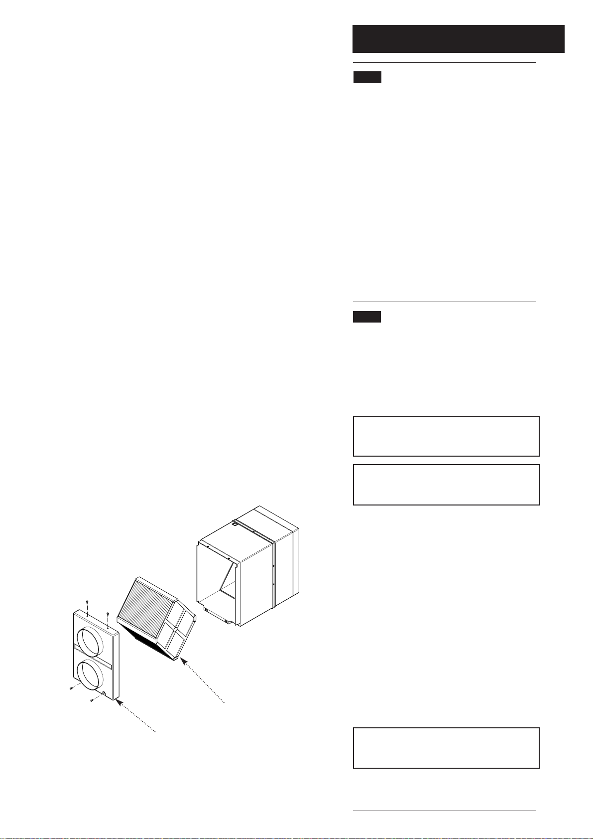
6. Remove the connection spigot plate, heat
exchanger, from the unit (Fig. 4).
Heat Exchanger
Fig. 4
Connection Spigot Plate
Page 7
3.0 Installation
7
3.3 Installing the Appliance
From Inside
1. Slide the unit into the mounting hole and
ensure that the minimum overhang requirements
are achieved inside and out (Fig. 5).
2. The HR300RW6 requires an overhang internal
and external (Fig. 6):
Internal 50mm
External 55mm
3. Pierce the blind grommet on the left hand side
on the top of the unit and feed the supply cable
through the grommet (Fig. 5)
4. Ensure that the unit is square and true with the
outside wall face. If firmer fixings are required,
secure the unit in place with the two fixing screws
provided.
NOTE: Ensure the fixings DO NOT inhibit
removal or replacement of the heat exchanger.
5. Make good around the case.
6. Fit the bezel on the inside to cover the making
good by pressing the bezel over the case (Fig. 7).
CAUTION: Ensure the case does not distort
during fixing and making good.
From Outside
1. Slide the panel flange (flange first) on to the
unit and press the flange firm against the outer
wall (Fig. 7).
2. Secure the panel flange to the wall using the
fixing screws provided. If necessary the panel
flange can be secured to the case by self tapping
screw 25mm long maximum.
280mm
380mm
Fig. 5
50mm
55mm
Fig. 6
Blind Grommet
Fig. 7
Panel Flange
Bezel
Internal External
3° Min
For Drainage
Page 8

4.0 Electrical
8
4.1 Electrical Connections
230V 50Hz 100W max
1. Wiring must be via a 3A fused switched spur
with a 3mm contact separation in each pole. The
wiring should be suitably (Basec or Har)
approved cable of appropriate current carrying
capacity.
2. Ensure that the mains power supply is
isolated prior to installation.
3. Remove the plug from the socket and connect
incoming wires to the appropriate terminals
(Figs. 7 & 8).
4. Replace plug into socket.
5. Slide the heat exchanger into the unit (Fig. 9).
6. Locate the connection spigot plate on to the
front of the unit and secure with the four screws
provided (Fig. 9).
7. Connect ducting to the 150mm spigots.
NOTE: Ensure the controller to be used is
wired in accordance with the instructions
supplied with the controller.
8. Switch on the mains electrical supply and
check the operation of the unit.
Fig. 7
Fig. 8
L
E
N
Fig. 9
Heat Exchanger
Connection Spigot Plate
Plug
Page 9
5.0 Maintenance
9
5.1 Cleaning the Unit
1. To ensure optimum performance, the unit
should be inspected every 6 months for build up
of dust or debri and washed every 12 months or
at periods determined by the level of
contamination experienced and according to the
following procedure.
2. Isolate the mains power supply.
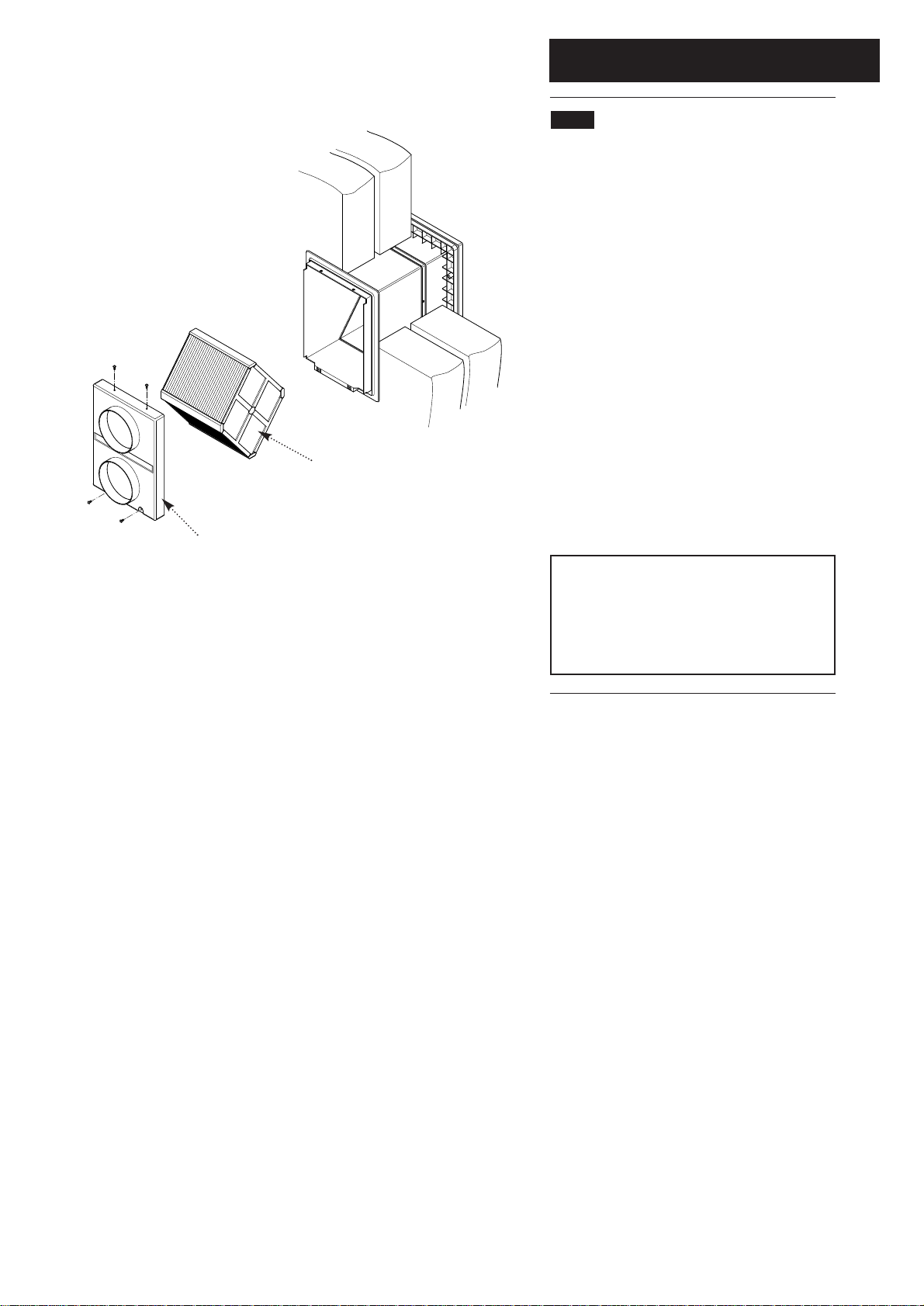
3. Undo the four securing screws and remove
the connection spigot plate (Fig. 10).
4. Slide out the heat exchanger (Fig 10). The
heat exchanger should be washed in warm
soapy water and dry thoroughly.
5. Reassemble in reverse order ensuring the
heat exchanger is seated correctly.
6. Switch power supply on and check the
operation of the unit.
NOTE: In heavy polluted internal
environments it is recommended that internal
grilles are fitted with simple washable filters
(ESG150). These filters should be removed
and washed on a regular basis (1-3 months)
or as conditions dictate.
Fig. 10
Heat Exchanger
Connection Spigot Plate
Page 10

6.0 Notes
10
Page 11

11
Page 12

Vent-Axia Ltd
Fleming Way
Crawley
West Sussex
RH10 9YX
www.vent-axia.com
Comp N
o
372561 - Iss B 0405
 Loading...