

Page 1
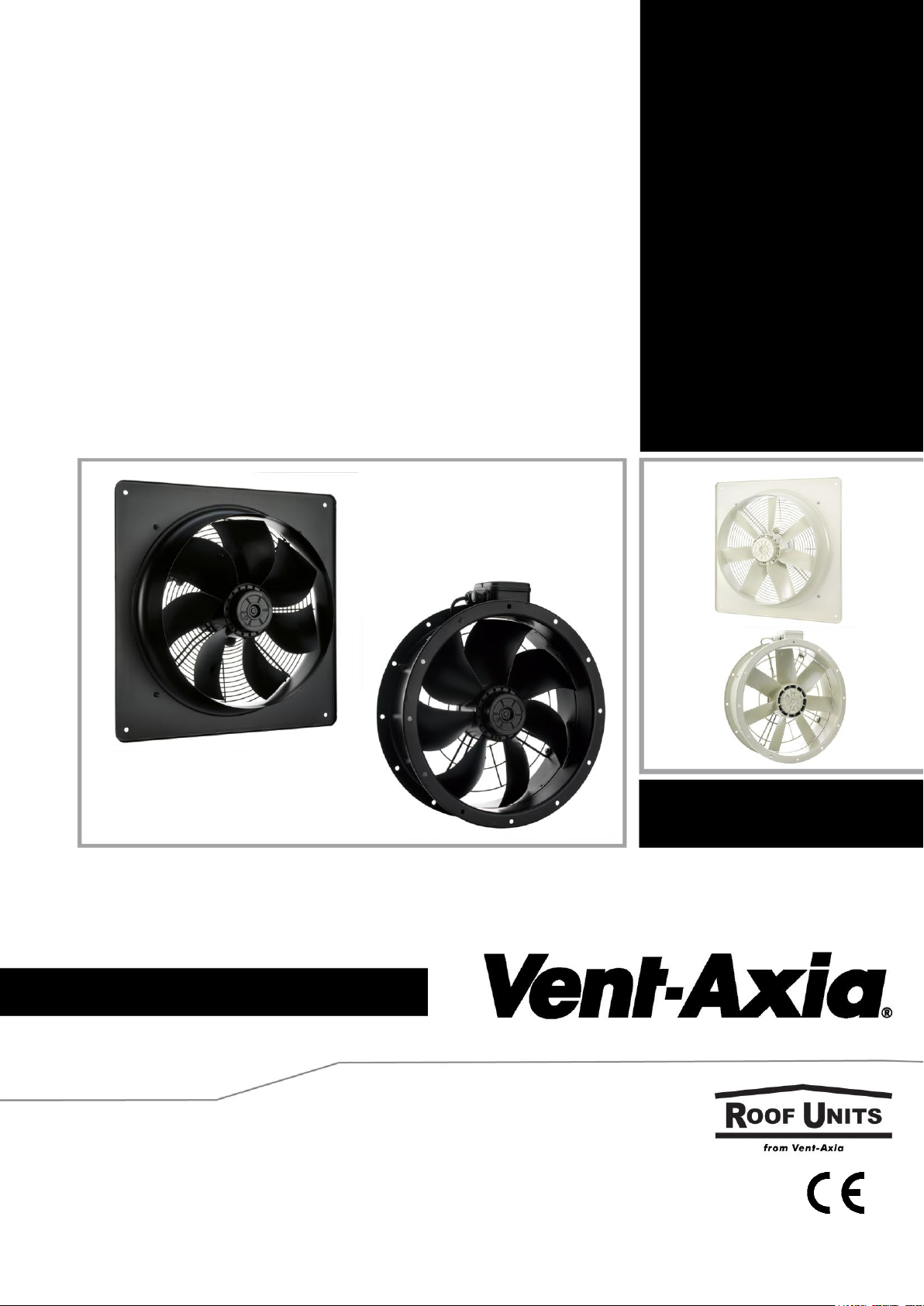
Installation and Wiring Instructions
PLEASE READ ALL INSTRUCTIONS CAREFULLY BEFORE STARTING INSTALLATION.
THESE INSTRUCTIONS SHOULD BE LEFT WITH THE END USER.
Sabre Short Case Sickle Fans (VSC)
Sabre Sickle Plate Fans (VSP)
Euroseries Short Cased Axial Fans (ESC)
Euroseries Axial Plate Fans (ESP)
Page 2

READ AND SAVE THESE INSTRUCTIONS
PLEASE READ ALL INSTRUCTIONS CAREFULLY BEFORE STARTING INSTALLATION. INSTALLATION AND WIRING
INSTRUCTIONS SHOULD BE LEFT WITH END USER.
Compliance with the following instructions is mandatory to ensure the functionality and safety of the product. If the
following instructions given especially but not limited for general safety, transport, storage, mounting, operating
conditions, start-up, maintenance, repair, cleaning and disposal /recycling are not observed, the product may not
operate safely and may cause a hazard to the life and limb of users and third parties.
Deviations from the following requirements may therefore lead both to the loss of the statutory material defect
liability rights and to the liability of the buyer for the product that has become unsafe due to the deviation from the
specifications.
Air moving equipment may present mechanical, electrical or noise hazards. To minimize risks associated with these
potential hazards, it is essential that safety, installation, operation and maintenance instructions are followed.
Implementation of these instructions should always be undertaken by technically competent personnel.
Potential mechanical hazards must be eliminated by guarding against access to the rotating parts whilst the air
moving equipment is operating. A range of guards are available for this purpose from Vent-Axia.
Installation work, both mechanical and electrical, must be undertaken in accordance with the safety and installation
instructions before switching on the unit.
Maintenance work should not be attempted before first switching Off and isolating the fan and its control from the
electrical supply and ensuring that it cannot be accidentally turned back on again. It is essential to ensure that
rotating parts have come completely to rest before maintenance work commences.
Air moving equipment may generate unacceptable noise levels when in operation. It may be necessary to take
appropriate action to reduce sound levels. A range of products are available for this purpose from Vent-Axia.
IMPORTANT
1. All electrical connections should be made by a properly qualified electrician. The fan must be sited and connected
in accordance with current IEE Wiring Regulations, BS7671 (U.K.), or the appropriate standards in your country.
2. DO NOT use this appliance when the following are generated or present: Excessive grease or oil laden air,
corrosive or flammable atmospheres.
3. When the fan is installed in a room containing a fuel burning appliance, the installer must ensure that the air
replacement is adequate for both the fan and the fuel burning appliance.
4. If a fan is used to supply air into a room, the installer must ensure that the fan intake is located at least 600mm
away from any flue outlet.
5. Site away from direct sources of heat, ambient temperature range -40oC to +70oC.
6. When installing unit, take care not to damage electrical or other hidden utilities.
7. Check the details on the rating label for correct voltage, frequency, speed, phase insulation class and IP rating.
8. Select the correct direction of rotation for the fan.
9. It is the responsibility of the installer to ensure that all aspects of system design are taken into consideration.
10. Due to the weight of larger units it is recommended that two people are involved in the installation.
11. Protective measures must be taken against falling parts when mounting with a hanging rotor.
FAN MOUNTING
CASED AXIAL FANS
1. A duct mounted in-line fan. Short duct runs terminating close to the fan (i.e. within 1.5m) require suitable
guards.
2. The fan can be mounted in a variety of ways and at any angle to suit the application.
3. Plan the installation carefully, taking into consideration the safety points noted above, before securely fixing the
fan using appropriate screws, bolts, rubber bushes, etc.
4. A range of accessories are available from Vent-Axia to assist installation including coupling flanges, flexible
connectors, mounting feet, anti-vibration mounts and a wire inlet guard.
Page 3

FORM OF RUNNING
Cased fans have arrows showing the direction of impeller rotation and airflow.
For reverse running the unit can be turned through 180o.
Alternatively, the airflow direction may be reversed by changing over the electrical
connections in the fan, but a drop in performance will result.
PANEL MOUNTED AXIAL
1. The fan is designed to be positioned in a panel or wall aperture.
2. The fan is suitable for mounting at any angle using the corner holes.
3. Ensure the fan impeller rotates freely before and after installation.
4. Plan the installation carefully, taking into consideration the safety points noted above,
before securely fixing the fan using appropriate screws, bolts, rubber bushes, etc.
5. If the fan is mounted less than 2.3m high, an external guard must be fitted. A range of Discharge Guards or
Louvre Shutters are available from the Vent-Axia accessory list.
FORM OF RUNNING
Panel mounted fans (ex-stock) are supplied for extract use (Form ‘A’ running). When used for intake, the fan can be
wired for reverse running, although performance will be reduced.
GENERAL WIRING INSTRUCTIONS
WARNING – THE FAN AND ANY ANCILLARY CONTROL EQUIPMENT MUST BE ISOLATED FROM THE POWER
SUPPLY DURING INSTALLATION AND/OR MAINTENANCE. THE EQUIPMENT MUST BE EARTHED.
1. All electrical connections should be made by a properly qualified electrician.
2. All wiring and connections must be carried out in accordance with current regulations.
3. It is recommended that an all pole isolator switch is fitted adjacent to the fan for safety during
maintenance/servicing.
4. Remove the cover from the terminal box to expose the main terminal block and the thermal protection block
(TB). The thermal protection device fitted is an automatic resetting type which must always be included in the
circuit. For ducted applications a manual reset is required, an ancillary circuit will be required with the TB switch
connected into the circuit.
5. Connect the power supply from the local isolator (via any appropriate controls if fitted) to the terminal box via an
appropriate cable gland. Refer to the wiring diagrams and select the appropriate connections for the fan,
controller or other devices as being installed. If in doubt please ask.
6. Ensure that all earth connections have been made.
7. After making connections inside the terminal box, replace the cover ensuring that the sealing gasket is in place.
Also ensure that all cable gland nuts, grommets etc. have been used correctly to prevent the ingress of water.
NOTES ON RUNNING
Before Connecting the power supply and running the Fan Check…
Are all links and wiring complete as per wiring diagram?
Are all fixings secure?
Are all relevant guards fitted?
Are all Circuit protection devices fitted?
Are all Terminal box covers and sealing glands secure?
Are all Earth connections secured?
Check that no hazard exists for persons in the locality of the fan. Switch on the fan and check that the fan
rotation is correct as per the direction arrows on the fan plate/casing. If not isolate power supply and
check wiring. For three phase fans interchange of any two phase leads on the supply will change rotation.
Check that the current (amps) taken by the fan does not exceed the current shown on the rating plate.
INSTALLER AND ELECTRICAL CONTRACTOR RESPONSIBILITY
Vent-Axia Ltd, as suppliers of the equipment cannot be responsible for the final installation and electrical
connection of the product on site. We have made reasonable effort to offer guidance and assistance but
the installer and electrical contractor on site have a responsibility for ensuring the equipment is safely and
securely installed and electrically/mechanically safe in accordance with statutory requirements.
The fans are supplied as a component to be incorporated into a ventilation system. The final complete
system installation that includes the fans MUST meet the requirements of:Low voltage Directive 2014/35/EU
Machinery Directive 89/392/CE
Electromagnetic Compatibility Directive 2014/30/EU
Page 4

If the fan is installed in an area where there is possible danger to safety or health then guards MUST be
fitted.
Guards suitable for many applications are available from Vent-Axia Ltd.
Please remember that fans need maintenance, cleaning and inspection. Allow for reasonable access for
these operations to be carried out safely.
If in doubt please ask.
ROUTINE INSPECTION/MAINTENANCE
THIS MUST BE UNDERTAKEN BY A COMPETENT PERSON.
ISOLATE UNIT FROM ELECTRICAL SUPPLY AND ENSURE THAT IT CANNOT BE ACCIDENTALLY
TURNED BACK ON.
1. We recommend that after three months the fan should be inspected and cleaned to remove deposits on
the impeller or motor. Thereafter, it should be checked and cleaned periodically as experience dictates,
or at least twice a year.
2. If a build up of dirt/deposits is evident then this should be carefully cleaned off. Please take care not to
damage the fan or affect the balance of the impeller motor assembly (balance weights may be fitted to
the impeller).
3. The fan motors are fitted with ‘sealed for life’ bearings and should not require maintenance under normal
circumstances.
4. The Ball-bearings service life – The according to standard calculation methods determined bearing service life
expectation of the motor integrated ball bearings is mainly determined by the grease service life F10h and
amounts for standard application to approx. 30.000 - 40.000 operating hours. The fan or motor is maintenance free due to the use of ball bearings with "lifetime lubrication". Once the grease operating life F10h has been
reached, it may be necessary to replace the bearing. The bearing service life expectation may change compared
to the specified value, if operating conditions such as increased vibrations or shocks, increased or too low
temperatures, humidity, dirt in the ball bearing or unfavourable control modes are present. A service life
calculation for special applications can be provided on request.
Operation Conditions:
1. Duty type of motor/fan
Continuous operation with occasional starts (S1) according to DIN EN 60034-1:2011-02. Occasional starting
between -40 °C and -25 °C is permissible. Continuous operation below -25 °C only with special bearings for
refrigeration applications on request.
2. Permissible minimal and maximal ambient temperature for operation
Please refer to the technical documentation of the product for the minimum and maximum ambient
temperature valid for the respective fan. Operation below -25 °C as well as partial load operation for
refrigeration applications is only possible with special bearings for refrigeration applications on request. If
special bearings for refrigeration applications are installed in the fan, please observe the permissible maximum
temperatures in the technical documentation of the product.
3. Any use below -10 °C is dependent on not being subjected to unusual, sudden or mechanical loads or stresses
on the material (see minimal permissible ambient temperature).
Page 5
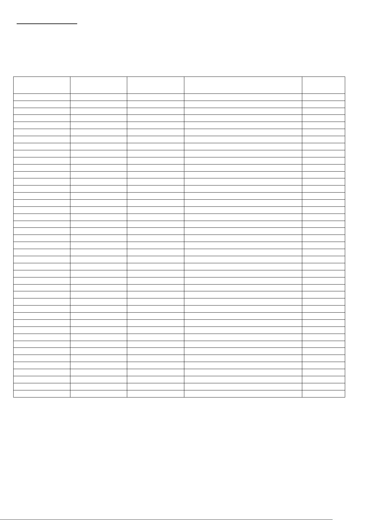
Wiring Diagrams:
VA Part
Number
Wiring
Diagram
Air Flow
Direction
Reversible (note if yes 40%
reduction in airflow
Voltage
ESC25012
177X
A
NO
230
ESP25012
177X
A
NO
230
ESC25014
177X
A
NO
230
ESP25014
177X
A
NO
230
ESP25032
106XB
A
YES
400
ESC31532
106XB
A
YES
400
ESP31532
106XB
A
YES
400
ESC31512
104XB
A
YES
230
ESP31512
104XB
A
YES
230
ESC31534
106XB
A
YES
400
ESP31534
106XB
A
YES
400
ESC31514
104XB
A
YES
230
ESP31514
104XB
A
YES
230
ESP35034
106XB
A
YES
400
ESC35014
104XB
A
YES
230
ESP35014
104XB
A
YES
230
ESP35016
104XB
A
YES
230
ESC40034
106XB
A
YES
400
ESP40034
106XB
A
YES
400
ESC40014
104XB
A
YES
230
ESP40014
104XB
A
YES
230
ESP40016
104XB
A
YES
230
ESC45034
106XB
A
YES
400
ESP45034
106XB
A
YES
400
ESC45014
104XB
A
YES
230
ESP45014
104XB
A
YES
230
ESP45016
104XB
A
YES
230
ESC50034
106XB
A
YES
400
ESP50034
106XB
A
YES
400
ESC50014
104XB
A
YES
230
ESP50014
104XB
A
YES
230
ESC56034
106XB
A
YES
400
ESP56034
106XB
A
YES
400
ESC56014
123XB
A
YES
230
ESP56014
123XB
A
YES
230
ESP56036
106XB
A
YES
400
ESP56016
104XB
A
YES
230
ESC63034
106XB
A
YES
400
ESP63034
106XB
A
YES
400
ESC63014
104XB
A
YES
230
ESP63014
104XB
A
YES
230
ESC63036
106XB
A
YES
400
ESP63036
106XB
A
YES
400
Important Notes:- The electrical circuit must be protected with an all pole isolator having a minimum of 3mm
contact separation with suitable fuses or circuit breaker.
For ducted applications the Thermal Protector (TB) must be connected into a control circuit in order to ensure that the
fan cannot restart before the fault condition is cleared and the circuit manually reset.
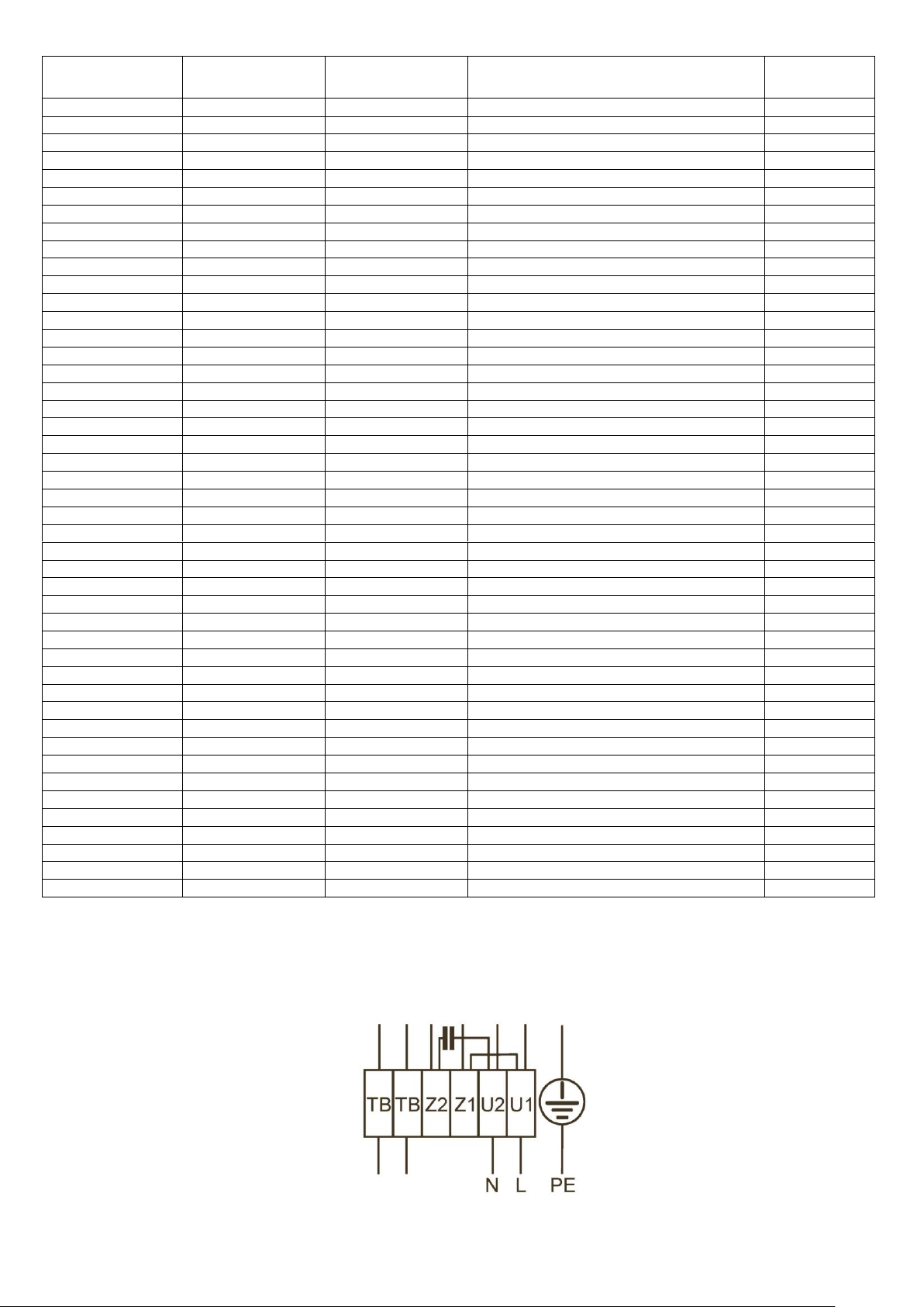
(Refer to table below, for the relative wiring diagram – each fan has a wiring label within terminal box)
Page 6
VA Part
Number
Wiring
Diagram
Air Flow
Direction
Reversible (note if yes 40%
reduction in airflow
Voltage
ESC63016
104XB
A
YES
230
ESP36016
104XB
A
YES
230
ESP63038
106XB
A
YES
400
ESC71034
106XB
A
YES
400
ESP71034
106XB
A
YES
400
ESP71036
106XB
A
YES
400
ESP71016
104XB
A
YES
230
ESP80034
106XB
A
YES
400
ESP80036
106XB
A
YES
400
ESP80038
106XB
A
YES
400
ESC100036
106XA
V
YES
400
ESP100036
106XB
A
YES
400
ESP100038
106XB
A
YES
400
VSP25012
177X
A
NO
230
VSP25014
177X
A
NO
230
VSC31514
177X
V
NO
230
VSP31514
177X
A
NO
230
VSP35514
177X
A
NO
230
VSC35534
108XA
V
NO
400
VSC40014
104XA
V
NO
230
VSP40014
104XB
A
NO
230
VSC40034
108XA
V
NO
400
VSP40034
108XB
A
NO
400
VSC45014
104XA
V
NO
230
VSP45014
104XB
A
NO
230
VSP45016
104XB
A
NO
230
VSC450346
108XA
V
NO
400
VSC50014
104XA
V
NO
230
VSP50014
104XB
A
NO
230
VSP50016
104XB
A
NO
230
VSC500346
108XA
V
NO
400
VSP500346
108XB
A
NO
400
VSC56014
104XB
A
NO
230
VSP56014
104XB
A
NO
230
VSP56016
104XB
A
NO
230
VSP560346
108XB
A
NO
400
VSP63016
104XB
A
NO
230
VSP630346
108XB
A
NO
400
VSC71016
104XA
V
NO
230
VSP71016
104XB
A
NO
230
VSC710368
108XA
V
NO
400
VSP710368
108XB
A
NO
400
VSC35514
177X
V
NO
230
VSP63014
104XB
A
NO
230
VSC63014
104XB
V
NO
230
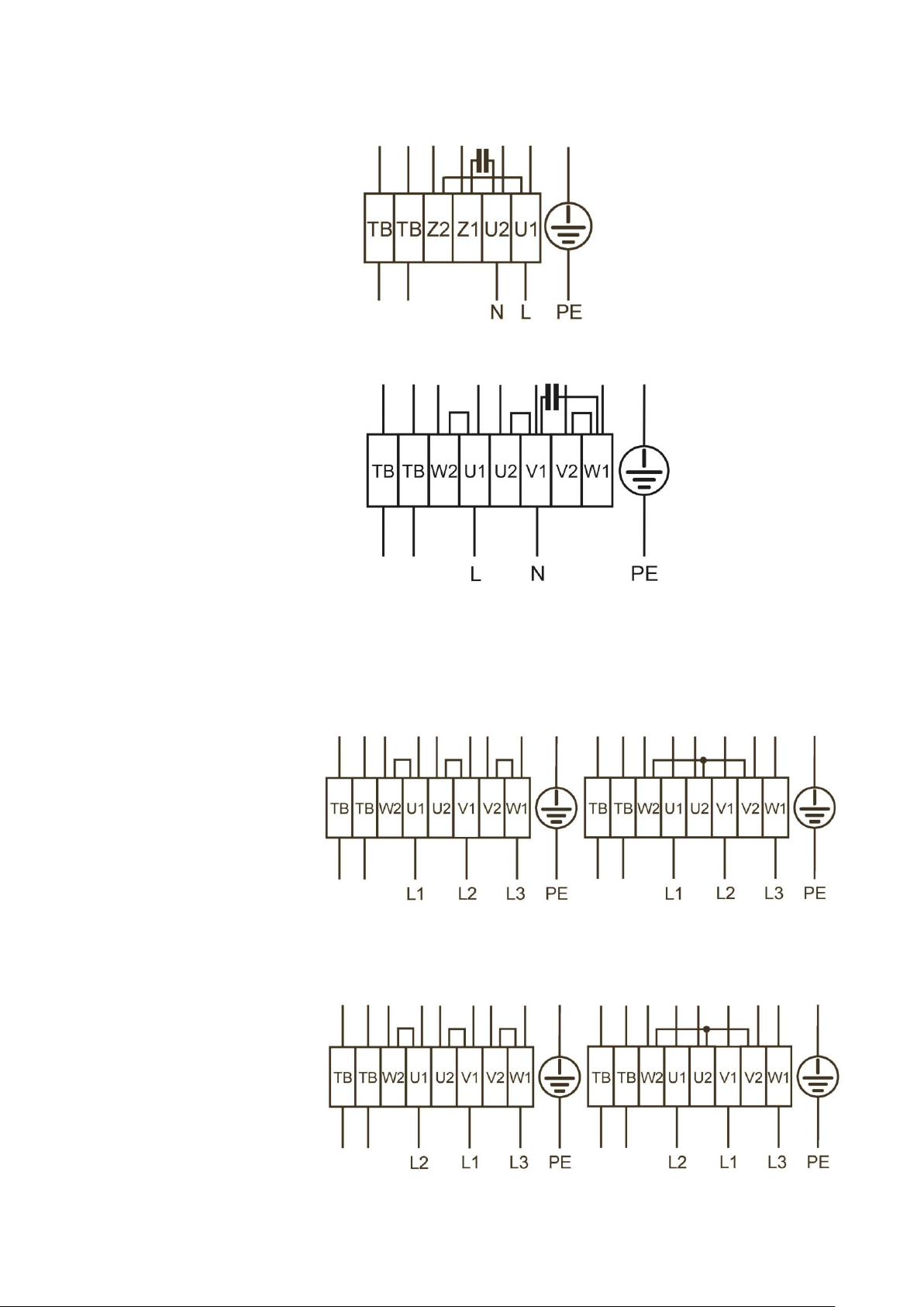
104XA
1 ~ Motor with capacitor and
thermostatic switch (if built in).
Airflow direction: V
Direction of rotation: Clockwise
Cable colours:
U1 Brown
U2 Blue
Z1 Black
Z2 Orange
TB White
Page 7
104XB
1 ~ Motor with capacitor and
thermostatic switch (if built in).
Airflow direction: A
Direction of rotation: Counter clockwise
Cable colours:
U1 Brown
U2 Blue
Z1 Black
Z2 Orange
TB White
123XB
1 ~ Motor with capacitor and
thermostatic switch (if built in).
Airflow direction: A
Direction of rotation: Counter clockwise
Cable colours:
U1 Brown
U2 Red
W1 Black
W2 Orange
V1 Blue
V2 Grey
TB White
106XA
3 ~ Motor with one speed and Δ-connection Y-connection
thermostatic switch (if built in).
Airflow direction: V
Direction of rotation: Clockwise
Cable colours:
U1 Brown
V1 Blue
W1 Black
U2 Red
V2 Grey
W2 Orange
TB White
106XB
3 ~ Motor with one speed and Δ-connection Y-connection
thermostatic switch (if built in).
Airflow direction: A
Direction of rotation: Counter
clockwise
Cable colours:
U1 Brown
V1 Blue
W1 Black
U2 Red
V2 Grey
W2 Orange
TB White
Page 8
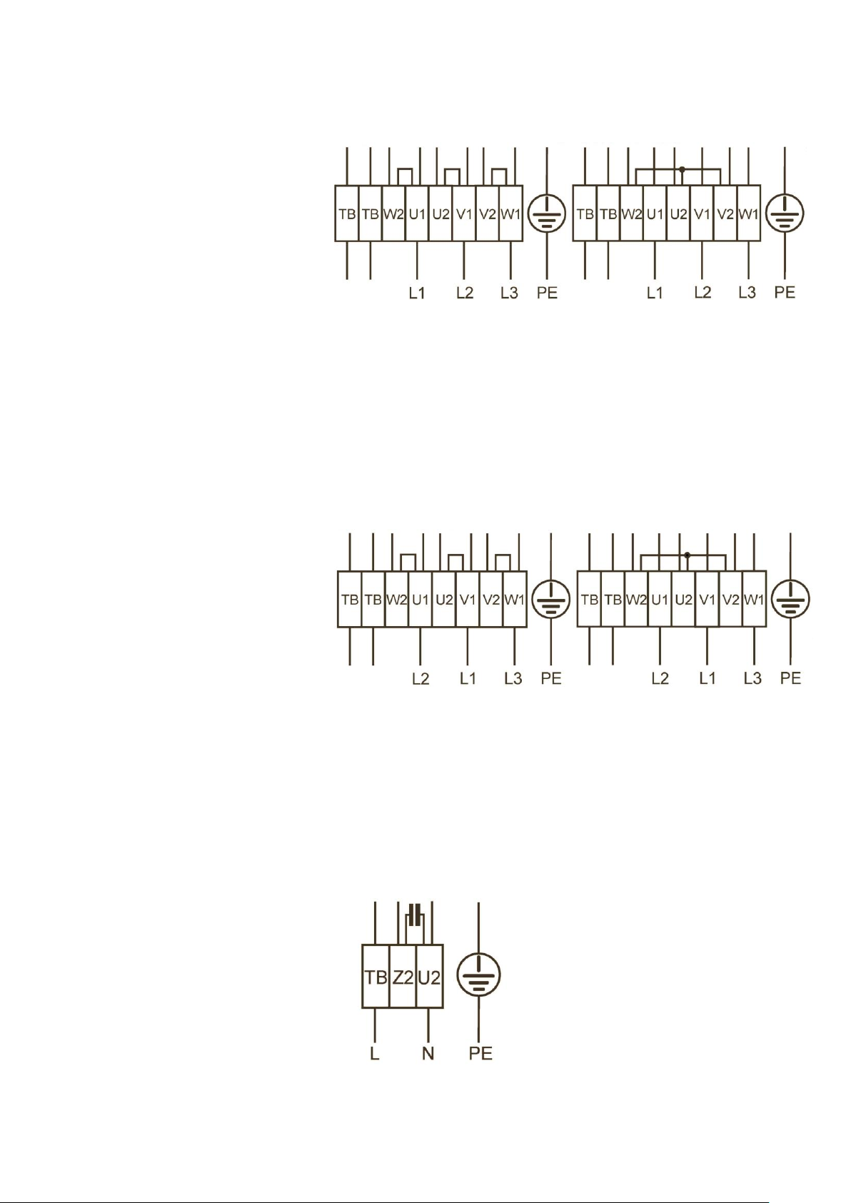
108XA
3 ~ Motor with 2 speeds High speed/Δ-connection Low speed/Y-connection
(Δ-/Y switch over) and
thermostatic switch (if built in).
Without bridge when using
speed change-over switch.
Direction of airflow: V
Direction of rotation: Clockwise
Cable colours:
U1 Brown
V1 Blue
W1 Black
U2 Red
V2 Grey
W2 Orange
TB White
108XB
3 ~ Motor with 2 speeds High speed/Δ-connection Low speed/Y-connection
(Δ-/Y switch over) and
thermostatic switch (if built in).
Without bridge when using
speed change-over switch.
Direction of airflow: A
Direction of rotation: Counter clockwise
Cable colours:
U1 Brown
V1 Blue
W1 Black
U2 Red
V2 Grey
W2 Orange
TB White
177X
1 ~ Motor with capacitor and Other speeds possible with capacitor
thermostatic switch. connected in series.
FN Series
Airflow direction: A
Direction of rotation: Counter-
clockwise rotation (looking at rotor)
FB Series
Airflow direction: A
Direction of rotation: Clockwise
rotation (looking at rotor)
Cable colours:
U2 Blue or Grey
Z2 Black
TB Brown
Page 9

Page 10

Page 11

Page 12
Head Office: Fleming Way, Crawley, West Sussex, RH10 9YX. Tel: 01293 526062 Fax: 01293 551188
UK NATIONAL CALL CENTRE, Newton Road, Crawley, West Sussex, RH10 9JA
SALES ENQUIRIES: Tel: 0844 8560590 Fax: 01293 565169
TECHNICAL SUPPORT: Tel: 0844 8560593 Fax: 01293 539209
For details of the warranty and returns procedure please refer to www.vent-axia.com or write to Vent-Axia Ltd, Fleming Way, Crawley, RH10 9YX
439031 F 0820
 Loading...