

Page 1
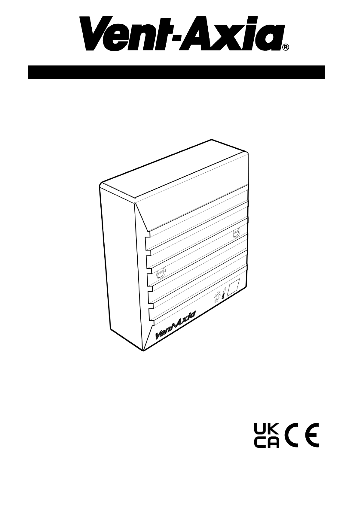
LO-CARBON AMBIENT RESPONSE HUMIDITY SENSOR
Fitting and Wiring Instructions
OPERATING RANGE: +5oC to +40oC, up to 90% RH
INPUT: 11-14V d.c.
MAXIMUM LOAD: 8-14V d.c. 5.6A
REF. No. 563552A
Please leave this document with the end user.
Page 2

PLEASE READ ALL INSTRUCTIONS CAREFULLY BEFORE INSTALLATION
OPERATION
This sensor is designed to respond to the severity
of moisture generating activity as well as the
ambient humidity and then to switch on an extract
fan. The pull cord will override the RH control and
switch the fan on to run continuously. The pull
cord should be pulled again to return the sensor
to the automatic mode i.e. to be activated by the
Humidity sensor. There is no permanent “OFF”
position.
Note to the installer and end user. When power
is first applied to the sensor, it will switch the fan
on for approximately 2 seconds to indicate the
power is connected. If the fan remains switched
on for more than 10 seconds, the pull cord should
be pulled once to check that the sensor is not in
override mode. (LED will go out). The LED ON
indicates that the Humidity sensor is in manual
override mode.
After initial start up the Humidity sensor will take
approximately 1 minute to acclimatise to the local
environment before entering its operational state.
SITING
• This sensor is not suitable for installation in a
shower cubicle or enclosure where water
droplets can cause damage to the sensing
element.
• Site the sensor on a wall away from direct
sources of heat and out of direct sunlight. Do
not site directly above a cooker or in an area
where excessive heat, smoke or grease is
present as this may affect the accurate working
of the Humidity sensor.
• Site the sensor away from the fan, on an inside
wall between the major moisture sources and
the door to the other rooms of the home,
position about 100mm (4”) below the ceiling
and preferably in direct sight of the fan i.e, not
in a dead spot behind or above a cupboard.
FITTING
The Humidity sensor is designed for fitting onto
any British single-gang outlet box, either surface
or recessed; which has a minimum depth of
20mm. A Vent-Axia surface mounting box (stock
ref. no.410020) is available.
WIRING
Warning
• Switch off mains before proceeding with wiring.
• Ensure mains supply is correct and the load
does not exceed sensor rating.
• The sensor (and any appliance) must be
installed in accordance with IEE regulations
(BS7671) in the UK or the appropriate
standards in your country.
• The sensor is a Class III SELV product and
MUST NOT be earthed. It must be connected
to an 11-14V d.c. SELV power supply which
can also provide power for a Vent-Axia LoWatt
fan.
Mains wiring to the transformer should be via a
switched spur fitted with a 3 amp fuse (UK). The
installation MUST be provided with a double pole
switch with contact separation of at least 3mm.
The switch should be located outside the room if
it contains a fixed bath or shower, or in
accordance with mandatory wiring and safety
regulations.
A total SELV cable run of not more than 20m is
recommended. The SELV wiring should be
physically separated and insulated from the mains
supply or other cabling. Cut the outer sheathing
back as little as possible so that the insulating
sheath almost reaches the terminal block. Cable
of cross sectional area not less than 0.75mm2 is
recommended.
Page 3
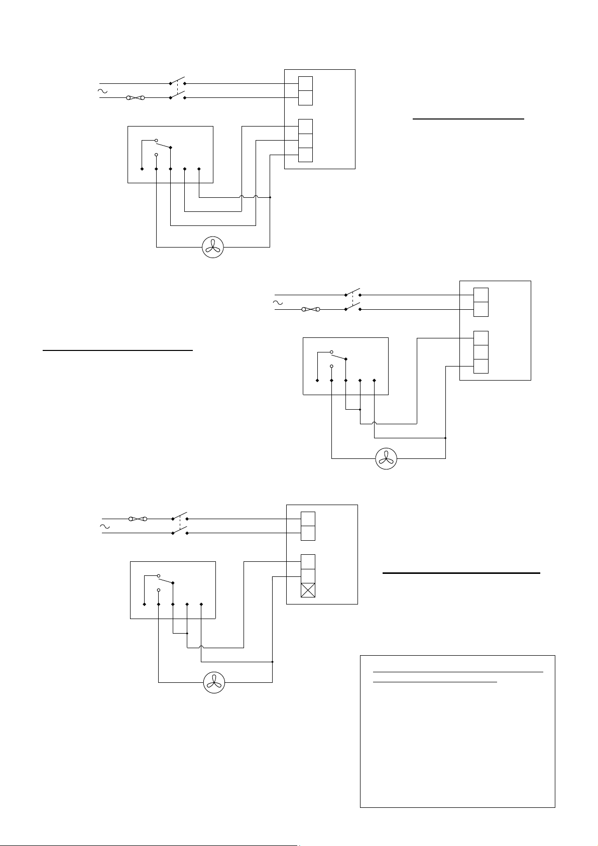
WIRING DIAGRAMS
DETAILS OF LOWATT AMBIENT RESPONSE
HUMIDITY SENSOR TERMINALS
1. d.c. (-ve) SUPPLY
2. 11-14V d.c. (+ve) SUPPLY
3. RELAY COMMON CONTACT
4. RELAY NORMALLY OPEN CONTACT
(CLOSES FOR RH% OR MANUAL OVERRIDE)
5. RELAY NORMALLY CLOSED CONTACT
(OPENS FOR RH% OR MANUAL OVERRIDE)
8
V
ve
-
1 2 3 4 5
11
V
MAINS
SUPPLY
220-
240
V
50
Hz
LOWATT AMBIENT
RESPONSE HUMIDITY
SENSOR
VENT-AXIA LOWATT FAN
+
-
L N L
N
VENT-AXIA LOWATT
TRANSFORMER
LOWATT TOILET FANS
A
3
N
L N L
5 1 2 3 4
V
11 8 V - ve
LOWATT AMBIENT
RESPONSE HUMIDITY
SENSOR
VENT-AXIA LOWATT
TRANSFORMER
+
-
MAINS
SUPPLY
220-
240 V 50
Hz
VENT-AXIA LOWATT FAN
LOWATT BATH / UTILITY FANS
A
3
3 2 1 5 4
MAINS
SUPPLY
220-
240 V 50
Hz
L N L N 3
A
LOWATT AMBIENT
RESPONSE HUMIDITY
SENSOR
VENT-AXIA LOWATT
TRANSFORMER
1
VENT-AXIA LOWATT FAN
2
+
ve
-
ve
LOWATT KITCHEN / SOLO FANS
Page 4
Head Office: Fleming Way, Crawley, West Sussex, RH10 9YX.
EU Authorised Representative: Vent-Axia Bedrijvenweg 17 7442 CX Nijverdal Nederland. [email protected]
UK NATIONAL CALL CENTRE, Newton Road, Crawley, West Sussex, RH10 9JA
SALES ENQUIRIES: Tel: 0344 8560590 Fax: 01293 565169
TECHNICAL SUPPORT: Tel: 0344 8560595 Fax: 01293 539209
For details of the warranty and returns procedure please refer to www.vent-axia.com or write to Vent-Axia , Fleming Way, Crawley, RH10 9YX
450988G 1121
The Guarantee
Applicable only to products installed and used in the United Kingdom. For details of guarantee outside the
United Kingdom contact your local supplier.
Vent-Axia guarantees its products for two years from date of purchase against faulty material or
workmanship. In the event of any part being found to be defective, the product will be repaired, or at the
Company’s option replaced, without charge, provided that the product:-
Has been installed and used in accordance with the instructions given with each unit.
Has not been connected to an unsuitable electricity supply. (The correct electricity supply voltage
is shown on the product rating label attached to the unit).
Has not been subjected to misuse, neglect or damage.
Has not been modified or repaired by any person not authorised by the company.
IF CLAIMING UNDER TERMS OF GUARANTEE
Please return the complete product, carriage paid to your original supplier or nearest Vent-Axia Centre, by
post or personal visit. Please ensure that it is adequately packed and accompanied by a letter clearly
marked “Guarantee Claim” stating the nature of the fault and providing evidence of date and source of
purchase.
The guarantee is offered to you as an extra benefit, and does not affect your legal rights
 Loading...