

Page 1
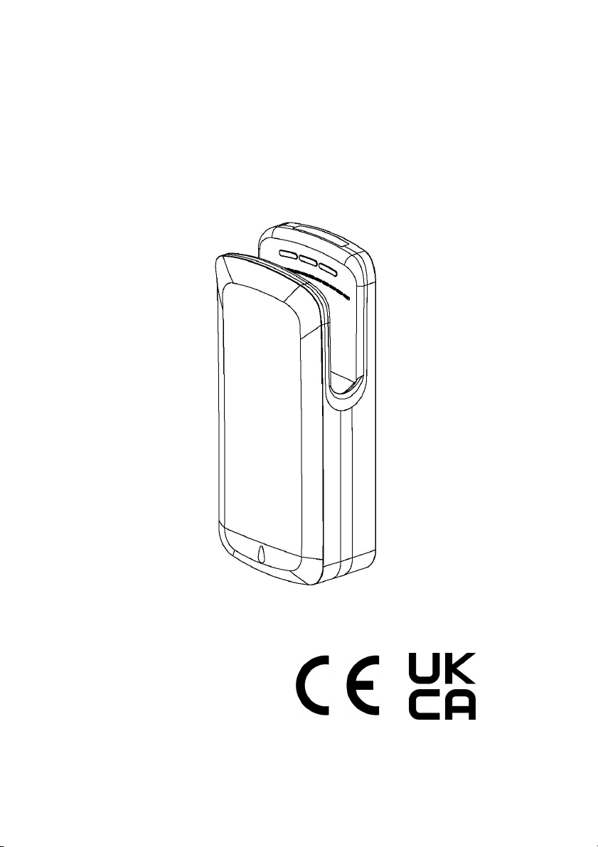
Jet Hand Dryer
Installation & User Manual
Ref:497484
Please read instructions in conjunction with the illustrations.
Please save these instructions.
Page 2

SAFETY WARNINGS
Before installing, be sure to read this installation manual and retain for future reference.
This product must be installed by qualified personnel in accordance with the instructions given
in this manual and installation must comply with all applicable regulations, national security
standards and laws in force in the country where the product is installed.
Tur n off the power at the main switch before installing or servicing the dryer unit
The dryer must not be installed on a flammable surface. Do not damage any parts of
the electrical connections.
Pre-arrange an appropriate power outlet and a system of disconnection in accordance with
current local regulations. Make sure the product is properly connected to ground. If there is
no ground connection, there is a risk of an electrical shock.
Do not install the dryer over a washbasin. If the power cord is damaged, it must be repaired
by qualified personnel to avoid any type of risk.
This dryer can be used by children aged 8 years and above. People with reduced physical,
sensory or mental abilities or lack of experience and knowledge, if they have been given
supervision and appropriate training regarding the use of the dryer in a safe manner, can use
it with no restriction. Children should not play with the apparatus. Cleaning and
maintenance performed by the owner should not be done without the children having
supervision.
During use, temperatures above 158℉ [70℃] may develop in the parts near the hot air nozzle.
Do not touch or cover the dryer during use or when finished using it.
General safety information:
WA R N I N G
WARNING
for installation by a qualified service person.
Use AWG NO .1 2 so li d co nd uc to r fo r wi ri ng .
WA R N I N G
DANGER
unit could result in service electrical shock
and/or death.
This product is intended
Failure to properly ground
--NOTE: Do not install dryer over washbasin --
WA R N I N G
WARNING
service breaker before installing or servicing.
WA R N I N G
WARNING
with a 3-wire service. The ground wire must
be connected to the dryer’s ba ck pl at e.
Disconnect power at the
All units must be suppllied
Page 3
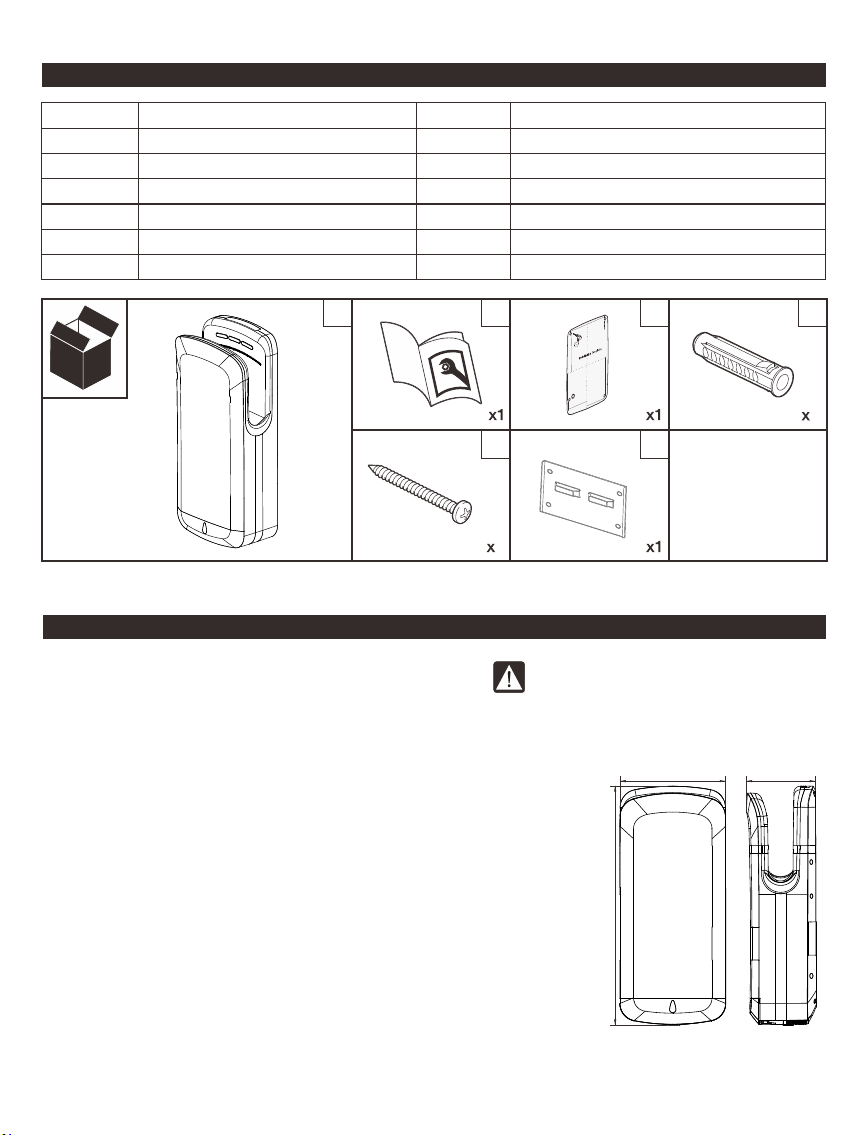
PACKING LIST
ITEM KEY
A
B
C
D
E
F
ITEM DESCRIPTION
Hand Dryer Unit Complete
Owner Manual(OM - this booklet)
Mounting Template(MT)
Wal l Anc ho rs , Ex pa ns io n
Self-threading Phillips PH Screws
Installation Bracket
A
ITEM QTY NOTES
High Impact ABS plastic
1
1
1
Φ6x28 MM [ 15/64" Dia. x 1-7/6 4"], fo r#5
8
M4x20MM [ No.8 AB x 25/32"]
8
Fixed on wall
1
B C
MT
E
8
SPECIFI CATION
Voltage: 220V-240 V 50/60 Hz, 7.17 A,1650 W
110V-120 V 60 Hz, 13.75 A, 1650 W
Stand-by Power: Less than 2.0 W
Air Temperature: 40 ℃[104 °F] (Room Temp.=25 ℃[ 77 °F ])
Air Velocity: 150 M/ S [ 492 FT/S ] / 540 KM/H [ 336MPH ]
Air Flow: 120 M /H [ 70.5 CFM ]
Drying Time: 8-10 Seconds
Timing Protection: Forced Hold-On 25 Seconds auto shut-off
Timing Duration: Auto Shut-Off ≤3 Seconds after last sensor read
Fuse Protection: Main PCB, Φ5x20, 250 V, 12 A[ 230 V ] / 20 A[ 120 V ]
Protection Level: IP23
Electric Isolation: CLASS II
Brush Motor: 30,000 RPM, 1250 W[ 1.7 HP ]
Noise [ at 1M ]: 70 dB
Net Weight: 8.8 KG [ 19.4 lb ]
Gross Weight: 10.6 KG [ 23.4 lb ]
3
ONLY be us ed o n sa me v ol ta ge
}
as product rated label marked.
[11-11/ 16 "]
671MM [26-7/16"]
F
297M M
D
8
195M M
[7-11/16"]
Page 4
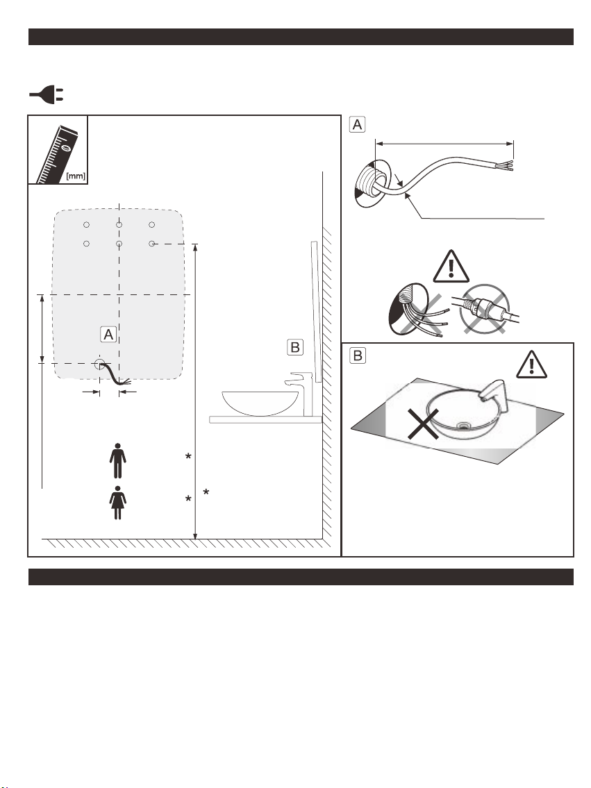
BEFORE IN STALLATION
Installation must be carried out in accordance with the current edition of the local wiring regulations
code having jurisdiction. Installation should be performed only by a qualified electrician.
Please check if hand dryer is supplied with convenient plug in feature.
If hand dryer is to be installed with hardwired
stub provided in advance of install by others.
See MT for complete reference to mounting
heights and power KO locations.
259M M[10 -1 3/ 64 "]
66MM [2-1 9/ 32 "]
860MM
[33-55/64"]
840MM
[33-5/64"]
Recommeded
L Min . = 50 0 MM [1 9- 11/16" ]
220-240V/ 12A
110-120V/ 20A
It is recommended to avoid installation
of dryer near high reflective objects
(mirror, stainless steel washbasins,
etc.) in order to avoid faulty function of
the presence sensor.
INSTALLATION
1. Make sure power supply breaker is switched off. Installation must adhere to the regulations of
the current edition of the local wiring code having jurisdiction. Installation should be performed
only by a qualified electrician.
2. Place Template against wall at desired height (see mounting height recommendations on MT) and
mark locations of eight (8) mounting holes and wire service entry at hard wire entrance.
Note: For two(2) or more dryers units, units should be no closer than 610MM[24"] on centers.
3. Drill the marked hole at Φ8MM / depth 38MM.
4. Insert Wall Anchors, Expansion [ D ] inside hole.
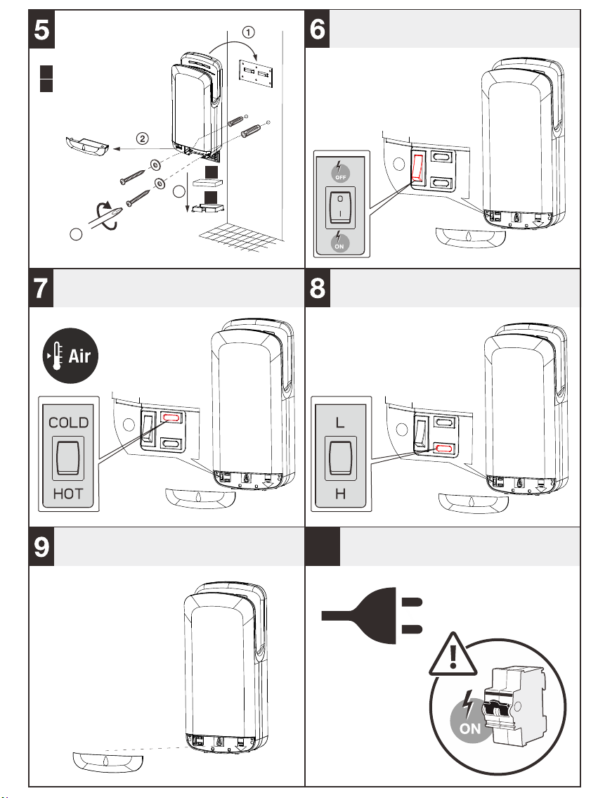
5. Fix Installation Bracket [ G ] on wall.
6. If the ha nd dryer is s upplied in ha rd wire typ e:
Page 5
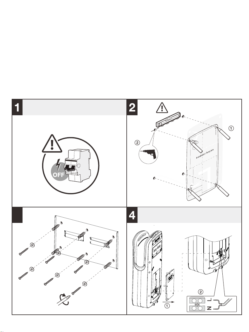
A. Open h and dryer bac k Term inal Block co ver.
B. Con nect live wir e(Colou red Brown, Re d, or Black ) to the termin al block ma rked “L”.
C. Con nect neutra l wire(Co loured Blac k, Blue) to t he terminal b lock mark ed “N”.
D. Rep lace Termi nal Block cov er.
E. Han g hand dryer on Wall Brac ket [ G ]. Slid i t lightly fro m up to down th en it is locked .
7. If ha nd dryer is sup plied wit h cable & plug th en do up acti on “ E ” to hang hand d ryer.
8. Mov e the hand drye r bottom Sw itch Cover. Lo ck hand dry er by two theft proof scr ews.
9. Bef ore replace S witch Cov er:
A. Chec k if the hand dry er power sw itch ON [ Left sw itch ].
B. There is an o ption to ru n the dryer hea t element O n or OFF[ Right u p switch ].
C. There is an o ption to ru n air speed Hig h or Low [ Righ t low switch ].
Ther e switch is cle arly mark ed too.
10. Re place the Swi tch Cover.
CIRCUIT BREAKER [By others]
Dia.Φ8ΜΜ[5/16"]
3
HARD WIRE ONLY
Page 6
Coars e Par icu la te Fi lte r
A
Air I nl et Wi ndo w
B
4
POWER ON/OFF OPTION
A
3
B
HOT AIR ON/OFF OPTION
10
AIRFLOW SPEED HIGH/LOW OPTION
PLUG IN/ TUR N ON CIRCUIT BREAKERREPLACE SWITCH COVER
Page 7
BASIC USE
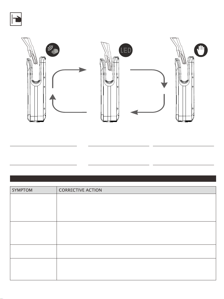
Operation without touching,
place your hands at drying
cavity to activate the device.
DIAGNOS TICS & REMED IES
Hand dryer fails to
start
Hand dryer turns
on/off erratically
or not sensitive
enough
Not hot air
Hand dryer makes
ticking noise
Ensure the breaker supplying the dryer is operational. If it is, disconnect the
power and remove the hand dryer cover.
Check all the wire connection to sure they are well fixed.
Tur n on p ow er a nd v er if y co rr ec t po we r at t er mi na l bl oc k. I f it d oe s no t wo rk
then replace circuit board.
Ensure that there is no obstruction on or in front of the infrared sensor zone.
Clean any dirt off the sensor lens.
Try a dj us ti ng t he s en si ti vi ty p ot en ti om et er o n pr og ra m bo ar d.
If it still does not still not work, replace circuit board and sensor board.
Check if the heat element switch is set for power on.
Check if the heat element is broken. If yes, replace with a new one.
Check the motor brush wear down condition. Replace them if worn out or
install a new motor.
Disconnect power, remove cover, check to make sure no object is stuck in
motor vents.
Externally visible service
blue LED light guides
hands to air flow.
After 3 seconds without
detecting hands, the device
stops automatically.
Page 8
HEPA CLEAN & RE PLACEMEN T
The service life of a HEPA filter depends on the environment in which the dryer is installed and
frequency of use. High traffic washrooms or high usage will require more frequent inspection and
replacement of the HEPA filter. Th e HE PA filter should be inspected at least four times per year in
washrooms with light to moderate traffic and normal environments.
In environments with excessive, dust and debris or in washrooms with high traffic, inspection of the
HEPA filter is recommended on a monthly basis. When visual inspection of the HEPA fil te r sh ow s
excessive buildup of lint, dust and debris, the filter should be replaced.
Examining and changing a HEPA filter regularly keeps hand dryers working effi ci en tl y.
Operating a hand dryer with an excessively dirty or clogged filter can damage your machine.
The HEPA filter cannot be cleaned and re-used. Do not clean the HEPA filter or allow it to come into
contact with water.
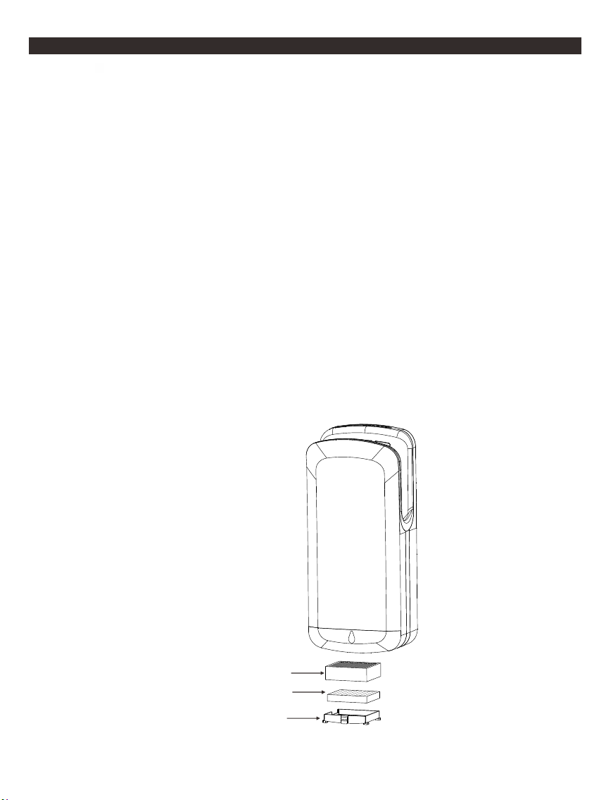
The hand dryer is also workable with Coarse Particulate Filter. The dryer has a coarse particulate air
filter to prevent lint and debris build up that can damage the motor and heating element. Routine
replacement or cleaning of the air filter is needed to maintain the dryer in good operating condition.
With light to moderate wash room traffic, replacing or cleaning the air filter once a year is
recommended.
If the wash room traffic is high, the air filter should be replaced or cleaned every 6 months.
HEPA Filter
Coarse Pariculate Filter
Air Inlet Window
Page 9
EMPTY WATE R TRAY
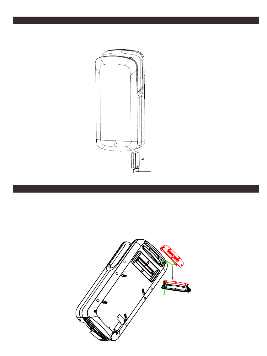
Regular empty water tray is required. The smart water level indicator is flashing when water is full. It
is available to push the water tray bottom piston to release water or move whole water tray unit to
empty it.
Wat er Tr ay
Available to connect a pipe to floor drain
Replace S ensor Dete ctor & LED Lig ht Circuit B oard
1. Move screw on sensor detector&LED light circuit board holder. Use a screwdriver to pull the cover
a little to open it.
2. Take cover out lightly and the circuit board will come together ! Be careful there is wire connected
on the circuit board.
3. Loosen two screws on circuit board and replace a new one.
Sensor Detector
&LED Light
circuit board
Page 10
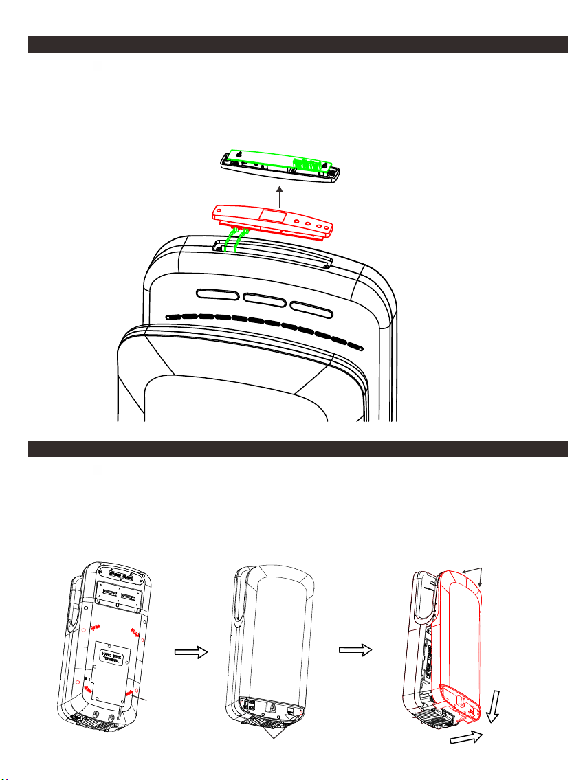
Replace D isplay Cir cuit Board
1. Move the sticker away. Do not damage the hand dryer edge as it will aff ec t th e su rf ac e ap pe ar an ce .
2. Move two screws on timer circuit board holder. Use a screwdriver to pull the holder a little to open it.
3. Take holder out and circuit board will come together. Be careful the connection wire.
4. Move two screws on circuit board and replace a new one.
5. Replacing new circuit board. It is suggested to use a new sticker for best appearance.
Display circuit board
Open Hand D ryer Front C over
1. Loosen 4 front cover screws on hand dryer back base as the arrow marked.
2. Loosen 2 front cover screws on the hand dryer front&bottom.
3. Pull the front cover up then back a little to take it.
4. Pull the cover slowly and slightly because there are plastic locks on the top side.
5. DO NOT damage the top side plastic locks because it is used to fix the front cover on the base.
Plastic locks
4 front
cover screw
2 front cover screw
Page 11
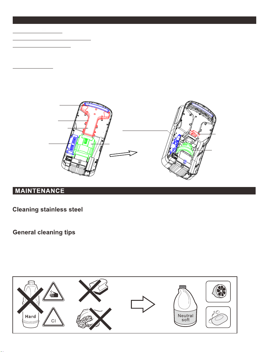
Repla ce M ain C ir cuit Bo ard, Se ns or Re ce iver Bo ar d, Mo to r, Heat El ement
Main Circuit Board: Move marked circuit board house cover and replace a new circuit board.
Sensor Receiver circuit board: .Move marked circuit board screw and replace a new one.
Replace Heat Element:
1. Move marked wind hole cover.Take the heat element out then replace a new one.
2. Replace wind hole cover. Be sure the air seal rubber at right location to avoid wind leakage.
Replace Motor:
1. Move marked wind hole cover and motor cover. Take the motor out and then replace a new motor.
2. Replace motor cover. Be sure the motor protection rubber&foam, air seal rubber at right location.
3. Replace wind hole cover. Be sure the air seal rubber at right location to avoid wind leakage.
Sensor Receiver
Circuit Board
Wind hole cover
Heat element house
Main circuit
board house
Main Circuit Board
Heat element
Motor house
Motor
Periodic cleaning of the unit is recommended. Remove cover and clean dryer dust lint.
Stainle ss steel is highly r esistan t to rust, bu t there are some ver y strict cleaning an d mainten ance rule s
to be fol lowed to prevent damage to it s appeara nce.
Apply neutral de tergents formulate d for these purposes (non-ion ic surfac tants and c itric aci d).
Apply the deterg ent with so ft cloth. Be careful with abr asive clo ths. Th ey may scra tch the surface.
Rinse with water u ntil all the deterge nt has go ne.
Residue from hyg iene prod ucts, liqui d soap, shampoos, bath gel, e tc, can als o damage surfaces.
Rinse the surfac e with plen ty of wat er after us e.
Limesca le stains can be pre vented by d rying the surface with a soft cloth af ter use.
Page 12
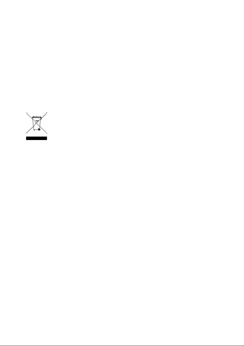
Disposal
This product should not be disposed of with household waste.
Please recycle where facilities exist. Check with your local
authority for recycling advice
.
PO BOX 1285, CRAWLEY, RH10 0LY
EU Authorised Representative: Anda Products Bedrijvenweg 17 7442 CX
Nijverdal Nederland [email protected]
497487A 0721
 Loading...