

Page 1
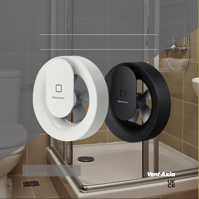
SVARA
Stylish and versatile bathroom fan
Instruction Manual
A product by
6
Page 2

Contents
Important Information 2
Installation and Wiring Instructions 3-11
Accessories 12
Pin Code 12
Important: READ THESE INSTRUCTIONS BEFORE COMMENCING THE INSTALLATION
DO NOT install this product in areas where the following
may be present or occur:
• Excessive oil or a grease laden atmosphere.
• Corrosive or flammable gases, liquids or vapours.
• Ambient temperatures are outside 5- 50°C.
• Possible obstructions which would hinder the access or
removal of the Fan.
SAFETY AND GUIDANCE NOTES
A. All wiring to be in accordance with the current I.E.E.
Regulations, or the appropriate standards of your
country and MUST be installed by a suitably qualified
person.
B. The Fan should be provided with a local isolator switch
capable of disconnecting all poles, having a contact
separation of at least 3mm.
C. Ensure that the mains supply (Voltage,
Frequency, and Phase) complies with the rating label.
D. The Fan should only be used in conjunction with the
appropriate Vent-Axia products.
E. The fan should only be used in conjunction with
fixed wiring.
2
F. When the Fan is used to remove air from a room
containing a fuel-burning appliance, ensure that the
air replacement is adequate for both the fan and the
fuel-burning appliance.
G. The Fan should not be used where it is liable to be
subject to direct water spray for prolonged periods
of time.
H. Where ducted Fans are used to handle moisture- laden
air, a condensation trap should be fitted. Horizontal
ducts should be arranged to slope slightly downwards
away from the Fan.
I. This appliance is not intended for use by young children
or infirm persons without supervision.
J. Young children should be supervised to ensure that they
do not play with the appliance.
K. The exterior grille should be at least 2.3m above the
ground to prevent people from being able to access
moving parts. If the external grille is positioned between
0-2.3m from the ground, please use the Vent -A xia wall
kit to ensure people cannot access the fans impeller
from the outside.
Operating and installation instructions
Page 3
Installer information
Installation
Installation Preparation
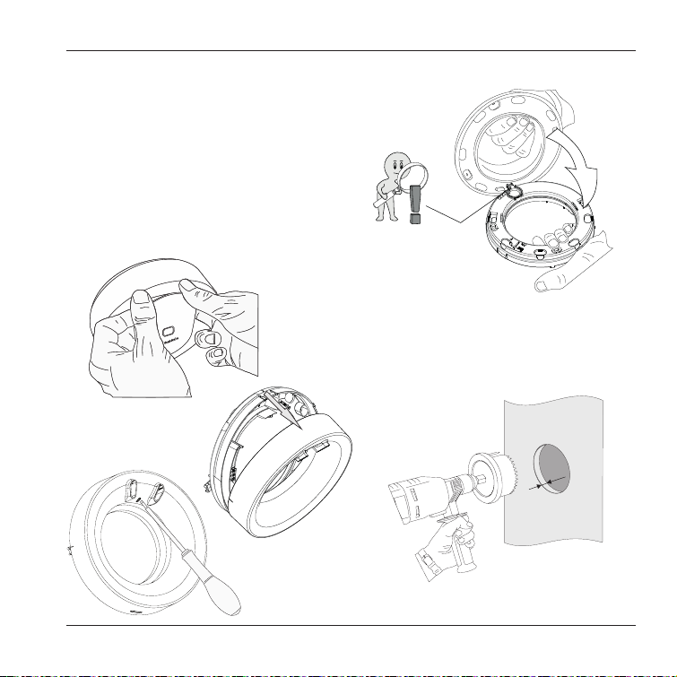
• Loosen the motor unit by grasping it as shown in Figure
(A), prise off the motor unit by leveraging against the cap
with your knuckles. Ensure that you have the motor unit in
a secure grip so you do not drop it when it loosens.
• Then loosen the wall frame by using a screw–
driver pressing the lock button as shown in Figure (B)
then remove the cover from the wall frame according to
figure (C).
A.
C
• Fit the enclosed wall
gasket as shown in
the figure (C_1).
C_1
New Installations
• New installations require holes using a
Ø110 mm hole saw (Figure D).
Ø 110 mm
5 mm
D.
B.
Operating and installation instructions
3
Page 4
Installer information
R75
45°
45°
45°
45°
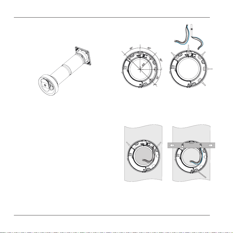
• Vent-Axia wall kits and external grilles are available as
accessories. (Figure E).
E.
The fan’s wall seal has a short spigot which fits inside the Ø100
mm pipe. Make sure when mounting to adapt the length of
the wall pipe so it does not push back the wall seal so the fan
impeller cannot rotate. Always customise a wall pipe, existing
or new, so it ends about 5 mm inside the wall surface where
the fan is to be installed. The wall frame with its seal is prepared
with 5 cable entry points (Figure F) for concealed electrical
connection or surface-mounted cable using the dimension
shown in Figure G.
• Make sure that the gasket is properly installed on the wall
frame, place it in the appropriate place and centre it in the
pipe.
The wall frame can be offset horizontally by placing a spirit
level on its support points
(Figure H and I).
• Use ageing-resistant sealant
to seal around cables that
are laid through the wall seal.
F.
H.
G.
I.
4
Operating and installation instructions
Page 5
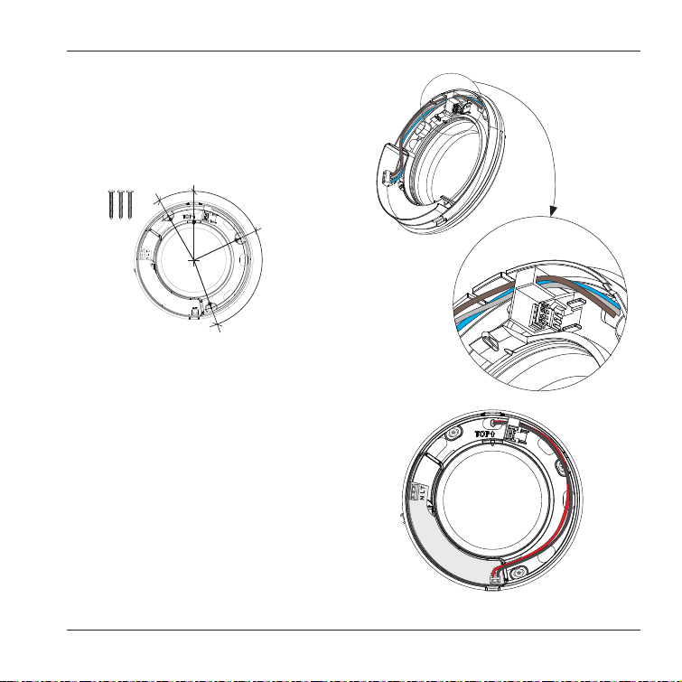
• Mark the three attachment points for the appropriate
screws to the substrate (Figure J).
Tighten the screws so that gasket seals against the wall.
Installer information
30°
65°
R75
95°
J.
Always use a qualified electrician
All electrical connections 100-240V must be performed by a
qualified electrician. Any electrical work on the product must
utilise a voltage break.
Electrical connection can be made according to the wiring
diagram on page 8-9 and the fan is suitable for connection to
either 100-240VAc or 12VDC.
NOTE: The internal cable route must be as indicated as
figures K/K1 (240VAC) and L (12VDC) to prevent the cable
blocking the locator’s for the motor assembly.
Operating and installation instructions
K.
100-240 V AC
connection
L.
12 V DC connection
K1.
5
Page 6
Installer information
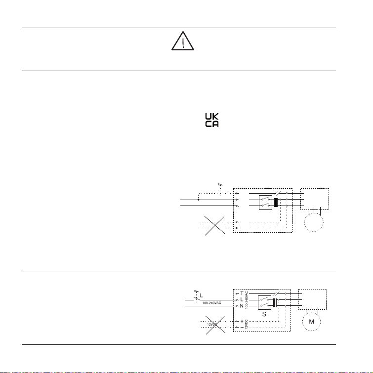
ELECTRICAL CONNECTION 100-240VAC
NOTE! Wiring of 100-240VAC must be
performed by a qualified electrician.
Svara auto:
100-240VAC 50 / 60Hz
Continuous trickle speed ventilation, automatic boost at
elevated humidity levels, and via the integrated light sensor.
Possibility to start / stop via manual switch T. Option of
accelerated air flow rate with 15 minutes’ run-on using
manual switch T.
Svara on/off operation through remote
switch, with overrun:
(Can be combined with backdraught shutter) 100-240VAC
50 / 60Hz Must be selected via Vent-Axia Connect App.
Start / stop via manual switch T. (start = max. RPM, stop =
15 minutes run-on time)
Svara humidity controlled:
(Can be combined with backdraught shutter) 100-240VAC
50 / 60Hz Must be selected via Vent-Axia Connect App.
Trickle setting, automatic start / stop on changes in humidity
levels. Possibility to start / stop via manual switch T. (start =
max. RPM, stop = 15 minutes run-on time)
Svara on/off operation through remote
switch:
(Can be combined with backdraught shutter)
100-240VAC 50 / 60Hz
Must be selected via Vent-Axia Connect App.
Start / stop via manual switch L.
NOTE! The integrated all-pole switch S only
functions at 100-240VAC wiring.
Bluetooth LE: -12dBm EIRP (63μW), nominal 2450MHz.
Radio Equipment Directive (RED)
NOTE: Vent-Axia hereby assure that this type of Bluetooth
radio equipment complies with RED Directive 2014/53 /
EU. The full text of the EU Declaration of Conformity can be
found at the following URL: http://bit.ly/2OyA8vY
6
NOTE: With T switch activated, the fan always
returns to max. speed after contact via app.
Any changes are only activated when the T input
is switched off and the run-on time has elapsed
T
T
100-240VAC
12VDC
L
N
100- 240VAC
S
+
_
12VDC
M
6
Operating and installation instructions
Page 7
Installer information
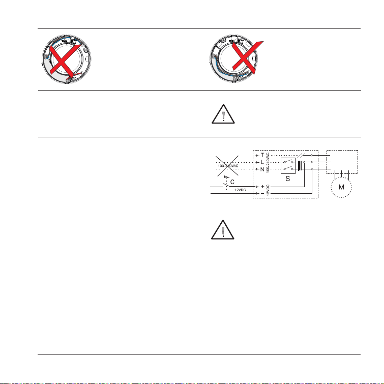
Connection of 100-240VAC
and 12VDC cannot be done
simultaneously (Figure N).
N. O.
ELECTRICAL CONNECTION 12VDC
NOTE. Vent-Axia recommends that electrical connection of
12 VDC be performed by a qualified electrician.
Svara auto:
12VDC (switch C always on)
Continuous trickle ventilation, automatic boost at elevated
humidity levels, and via the integrated light sensor.
Svara on/off operation through remote
switch:
(Can be combined with backdraught shutters)
12VDC
Must be selected via Vent-Axia Connect App.
Start / stop via manual switch C.
Svara humidity controlled:
(Can be combined with backdraught shutters)
12VDC (switch C always on)
Must be selected via Vent-Axia Connect App.
Trickle setting, automatic start / stop
on changes in humidity levels.
No 100-240V wiring may penetrate
the electronics portion (Figure O.)
NOTE! 12VDC voltage must not exceed
between 10 - 13,6VDC.
NOTE! For 12VDC always use switches
intended for direct current, C.
Operating and installation instructions
7
Page 8
Installer information
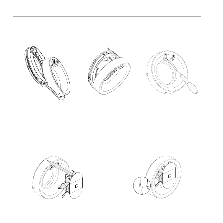
Mounting the cover on the wall frame
• The fan is double insulated and must not be earthed. When the electrical connection is made place the cover back over the
wall frame fitted into the housing hole (Figure P).
P.
Q.
R.
• Next, fold the cover over the wall frame (Figure Q).
• Ensure the catch the screwdriver is pointing to (Figure R) engages properly.
• Make sure that the cover is firmly seated in the hook on the wall frame and latch by pulling a bit of cover.
• Finally put the motor unit in place (Figure S). Be careful when fitting motor unit, the impeller can be damaged if the unit is
forced in at an angle.
• A distinct ’click’ sound confirms that the device is in place, check that the integrated On switch works freely before turning on
according to (Figure T).
0
0
1
1
S.
8
T.
Operating and installation instructions
Page 9
For the user
Vent-Axia Svara
®
Automatic functions and settings via app
Default setting:
Vent- Axia Svara is programmed to cope with the vast
majority of installations.
The fan works continuously at a trickle f low of 10l/s.
When the fan senses somebody in the room it increases
the flow to 16l/s.
If the humidit y rises rapidly, for example when the shower
is on, the fan goes up to maximum flow at 30l/s.
When the fan senses the humidit y level has returned to
normal it reverts to the trickle flow of 10l/s.
If other settings or functions are desired, download the
Vent- Axia Connect App from the App Store and Google
Play.
Requirements for functionality
Versions of the operating systems are updated continuously,
for information go to: www.vent-axia.com/svara.
Fault indication:
Red LED on the fan indicates power failure when the
calendar function has been activated.
Activate the app:
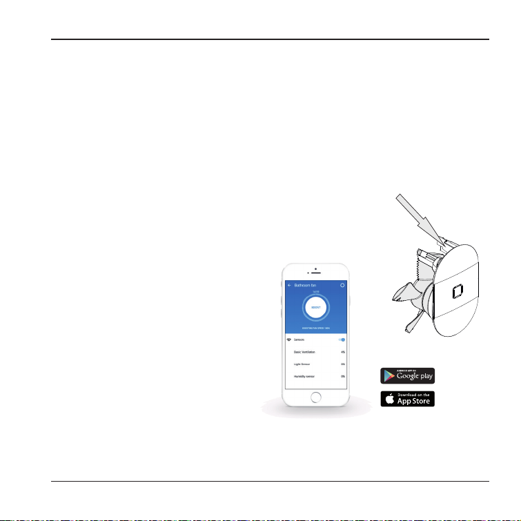
You have to use a code to activate the app, the code is
unique for each fan. Enter the code or scan it through your
phone. Your unique code is on the right leg of the motor unit
(Figure T).
Learn more about all the possibilities with our app
at www.vent-axia.com/svara
T.
Operating and installation instructions
9
Page 10
For the user
Servicing and maintenance
WARNING: THE FAN AND ANCILLARY CONTROL EQUIPMENT MUST BE
ISOLATED FROM THE POWER SUPPLY DURING MAINTENANCE.
Strong solvents should not be used on the fan.
The fan must not be dipped in or sprayed with water. For the
fan to operate correctly it must be cleaned at least twice a
year, more often if
necessary.
– Before cleaning, switch off the power to the fan
(Figure U).
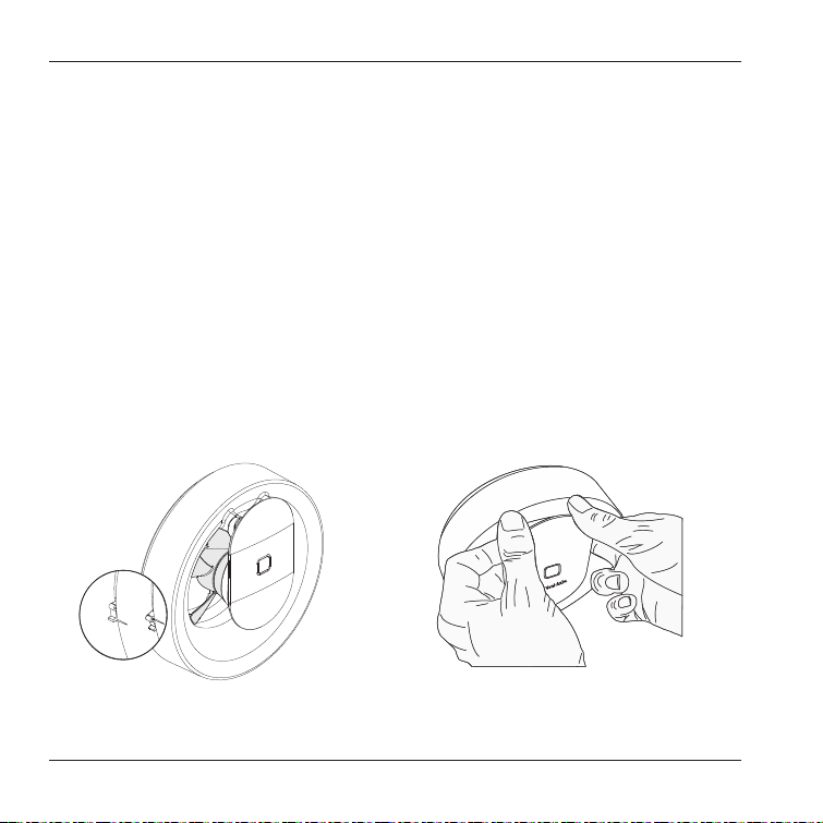
– Loosen the motor unit by grasping it (Figure V), prise off
the motor unit by leveraging the cap with your knuckles.
Ensure that you have the motor unit in a secure grip so
you do not drop it when it loosens.
0
0
1
1
U.
10
– Clean opening, the duct and the motor unit with a damp
cloth (if necessary, use a mild detergent).
– The impeller does not detach and should be wiped clean
in its position on the motor housing
– If the fan has an external backdraught shutter the shutter
should be cleaned gently.
– Replace the motor unit in the frame.
Eco
Discarded fans should be submitted as electronic waste to
the recycling centre.
V.
Operating and installation instructions
Page 11
For the user
The Vent-Axia Guarantee
Applicable only to products installed and used in the
United Kingdom. For details of guarantee outside the
United Kingdom contact your local
supplier.
Vent- Axia guarantees its Lo- Carbon products for five
years from date of purchase against fault y material or
workmanship. In the event of any part being found to
be defective, the product will be repaired, or at the
Company’s option replaced, without charge, provided
that the product:
• Has been installed and used in accordance with the
instructions given with each unit.
• Has not been connected to an unsuitable electricity
supply. (The correct electricity supply voltage is shown
on the product rating label attached to the unit).
• Has not been subjected to misuse, neglect or damage.
• Has not been modified or repaired by any person not
authorised by the company.
IF CLAIMING UNDER TERMS OF GUARANTEE
Please return the complete product to your original
supplier. The guarantee is offered to you as an extra
benefit, and does not af fect your legal rights.
Safe Water Installation
This product conforms to industry regulations for electrical
safety.
Supplier guarantees the functioning of the relevant
regulations and instructions are complied with.
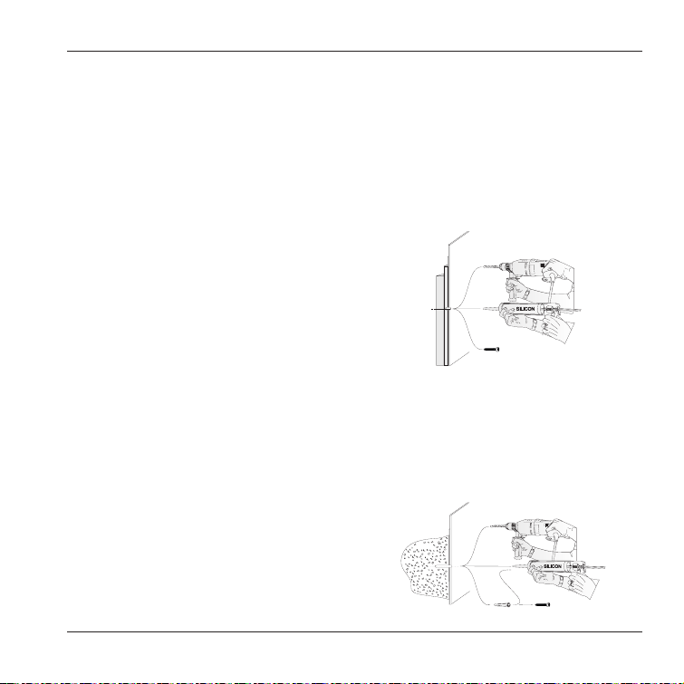
All the holes for the screws to be carried out according to
the figures X and Y.
X.
For Wallcoverings Wooden (Figure Y), drill only through the
coating and waterproofing.
NOTE: Never drill through any plywood.
Fill the entire hole with age-resistant sealing compound.
Use plumbing screws, screw through the plywood into the
regulatory framework.
Y.
Operating and installation instructions
11
Page 12
2.
1.
3.
EU Authorised Representative:
Vent-Axia Bedrijvenweg 17 7442 CX Nijverdal
Nederland
[email protected]
Head Office:
Fleming Way, Crawley, West Sussex, RH10 9YX.
SALES ENQUIRIES:
Tel: 0844 8560590 Fax: 01293 565169
TECHNICAL SUPPORT:
Tel: 0344 8560594 Fax: 01293 532814
Pin Code for app
To access the application:
PIN-code for your fan can you find on the right leg of the
motor unit. See page 9.
Write in the PIN-code into the square to the left to save it.
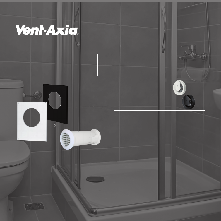
1. Fan Vent- Axia Svara- White
Stock Ref. 409802
2. Fan Vent-A xia Svara- Black
Stock Ref. 496711
Accessories available:
(purchased separately)
1. Cover Plate - White
for duct dimensions bet ween Ø140 -160
Stock Ref. 409820
2. Cover Plate - Black
for duct dimensions bet ween Ø140 -160
Stock Ref. 497117
3. Internal Fit Wall Kit - White
with Backdraught Shut ter
Stock Ref. 474779
009-500011-H 2021-05-04
© Copyright Vent-Axia®
We accept no liability for printing errors and reserve the right to make changes to materials and designs.
40 9821F
 Loading...