

Page 1
Lo-Carbon
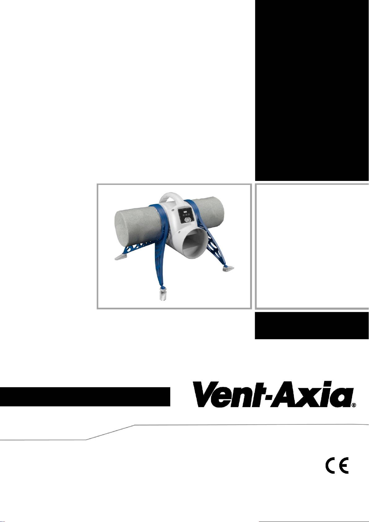
PureAir Home
Positive Input Ventilation
Unit
Stock Ref. N°
479090 – PureAir Home
479091 – PureAir Home with Heater
479092 – PureAir Home FD
Installation and Wiring Instructions
220-240V~50Hz
PLEASE READ INSTRUCTIONS IN CONJUNCTION WITH THE ILLUSTRATIONS.
PLEASE SAVE THESE INSTRUCTIONS
Page 2

2
Installation and Wiring Instructions for the
Lo-Carbon PureAir Home Positive Ventilation Unit.
IMPORTANT:
READ THESE INSTRUCTIONS BEFORE COMMENCING THE INSTALLATION
SAFETY AND GUIDANCE NOTES
1. DO NOT install this product in areas where the following may be present or occur:
1.1. Excessive oil or a grease laden atmosphere.
1.2. Corrosive or flammable gases, liquids or vapours.
1.3. Ambient temperatures higher than 40°C or less than -5°C.
1.4. Possible obstructions which would hinder access or removal of the Fan.
1.5. Relative humidity above 90%
1.6. Sudden ductwork bends or transformations close to the Unit.
2. All wiring to be in accordance with the current I.E.E. Regulations, or the appropriate standards
of your country and MUST be installed by a suitably qualified person.
3. The fan should be provided with a 3A fused, isolator switch capable of disconnecting all poles,
having a contact separation of at least 3mm.
4. Ensure that the mains supply (voltage, frequency, and phase) complies with the fan’s rating
label.
5. The fan should not be used where it is liable to be subjected to direct water spray.
6. This appliance is not intended for use by persons (including children) with reduced physical,
sensory or mental capabilities, or lack of experience and knowledge, unless they have been
given supervision or instruction concerning use of the appliance by a person responsible for
their safety.
7. Children should be supervised to ensure that they do not play with the appliance.
8. Precautions must be taken to avoid the back-flow of gases into the room from the open flue of
gas or other fuel-burning appliances.
A. INTRODUCTORY NOTES
The Vent Axia Lo-Carbon PureAir Home is a positive input ventilation unit, designed to be installed in the loft of a
dwelling to continually supply filtered fresh air into the building.
The system consists of a fan unit, an optional heater unit and a diffuser with a short length of flexible ducting.
The Lo-Carbon PureAir Home has two fully adjustable speed settings; ‘Trickle’ and ‘Energy Recovery’. These
speeds are set during installation; there are 5 pre-set speeds or an option allowing the speeds to be chosen
manually from 10L/s to 60L/s.
The Lo-Carbon PureAir Home uses a sensor to monitor the temperature in the loft, automatically adjusting the air
volume when necessary.
‘Trickle’ speed is automatically selected when the ambient loft temperature is less than 18°C.
‘Energy Recovery’ is automatically selected when the ambient loft temperature is between 18 and 27°C.
If the ambient loft temperature exceeds 27°C, the Lo-Carbon PureAir Home will automatically switch to standby (no
airflow).
For the model supplied with a heater units (479091 & 479092), the element is activated by default when the loft air
temperature is below 10°C; the system will then work to maintain an input air temperature of 10°C. This temperature
threshold can be adjusted between 5°C and 20°C during commissioning.
The heater unit can be installed either to the fan unit or directly to the diffuser spigot.
Page 3
3
B. INSTALLATION
Fig.1.
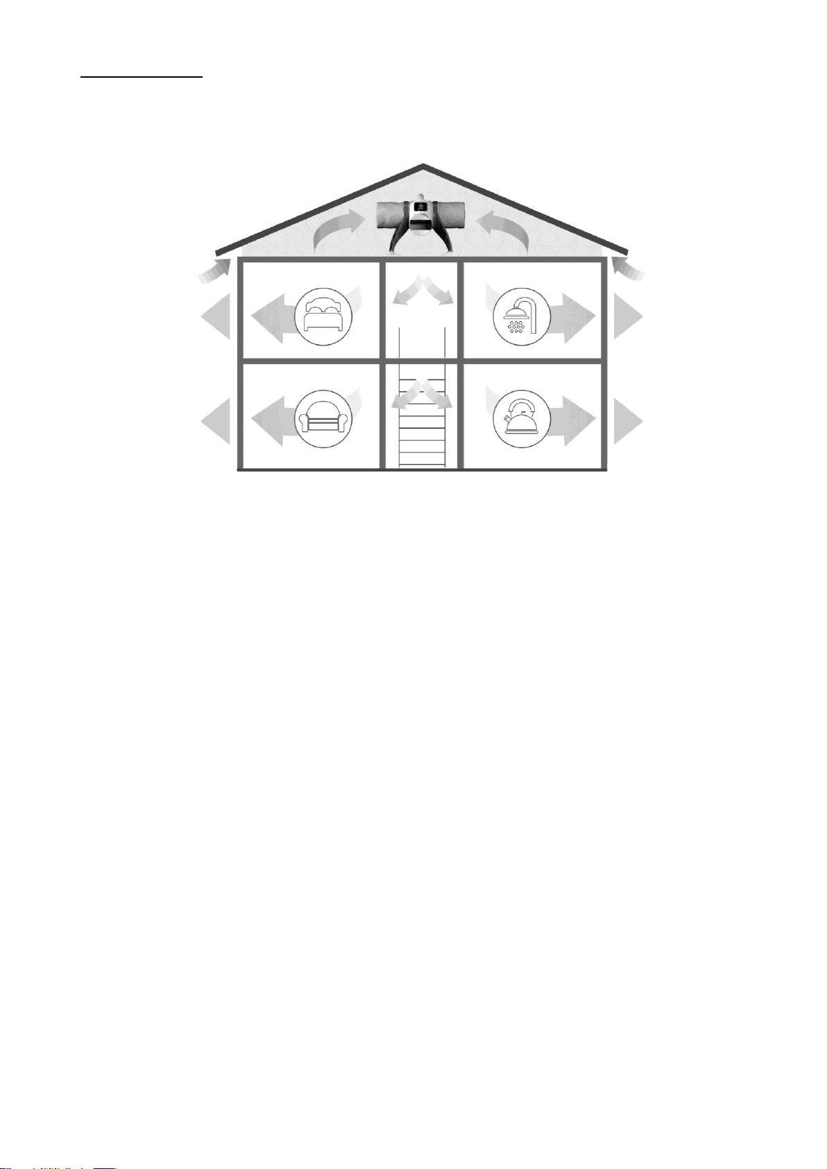
TYPICAL INSTALLATION
Lo-Carbon PureAir Home UNIT:
Prior to installation ensure that the loft is adequately ventilated. The following tips can be used as a basis for this.
However this is not an exhaustive list.
Ensure that any ridge vents, tile vents and continuous air gaps are not blocked. These may not be present in older
properties; however there should be enough ‘leakage’ to accommodate the requirements of the Lo-Carbon PureAir
Home unit.
One method of checking this is by entering the loft, closing the loft hatch, switching off the lights and looking for any
daylight penetration. If daylight is visible it is reasonable to assume that there is adequate ventilation within the loft.
There may well be occasions where a loft is so well sealed that additional ventilation may need to be provided by the
owner/occupier. This will not only assist the operation of the Lo-Carbon PureAir Home, but may also help to prevent
future expensive structural damage caused by inadequate air movement. It should be noted that there can never be
too much ventilation in a loft.
Ensure that all water tanks are covered and sealed.
Check that all water pipes are lagged.
Ensure that any extract fans are discharging to the outside and not into the loft.
Check that the loft hatch is tightly sealed.
Ensure that all holes in the ceilings are sealed, i.e. ceiling light fittings etc.
A visual inspection of any flues or chimneys for leakage in the loft should be carried out by the installer.
If any leakage points are found, or if there is any doubt at all, the installer should advise the house owner/provider as
soon as possible and seek instruction from them before proceeding with the installation.
Flexible ducting is supplied as standard. Ensure that this is pulled out and does not allow any moisture to collect; it
should be a smooth single curve to the grille. If the application requires a fixed 90 degree bend, straight ducting may
be used. See Spares and Accessories on page 11.
Page 4
4
Hanging method:
Fig. 4.
Fig. 3.
Fig.2.
Filters
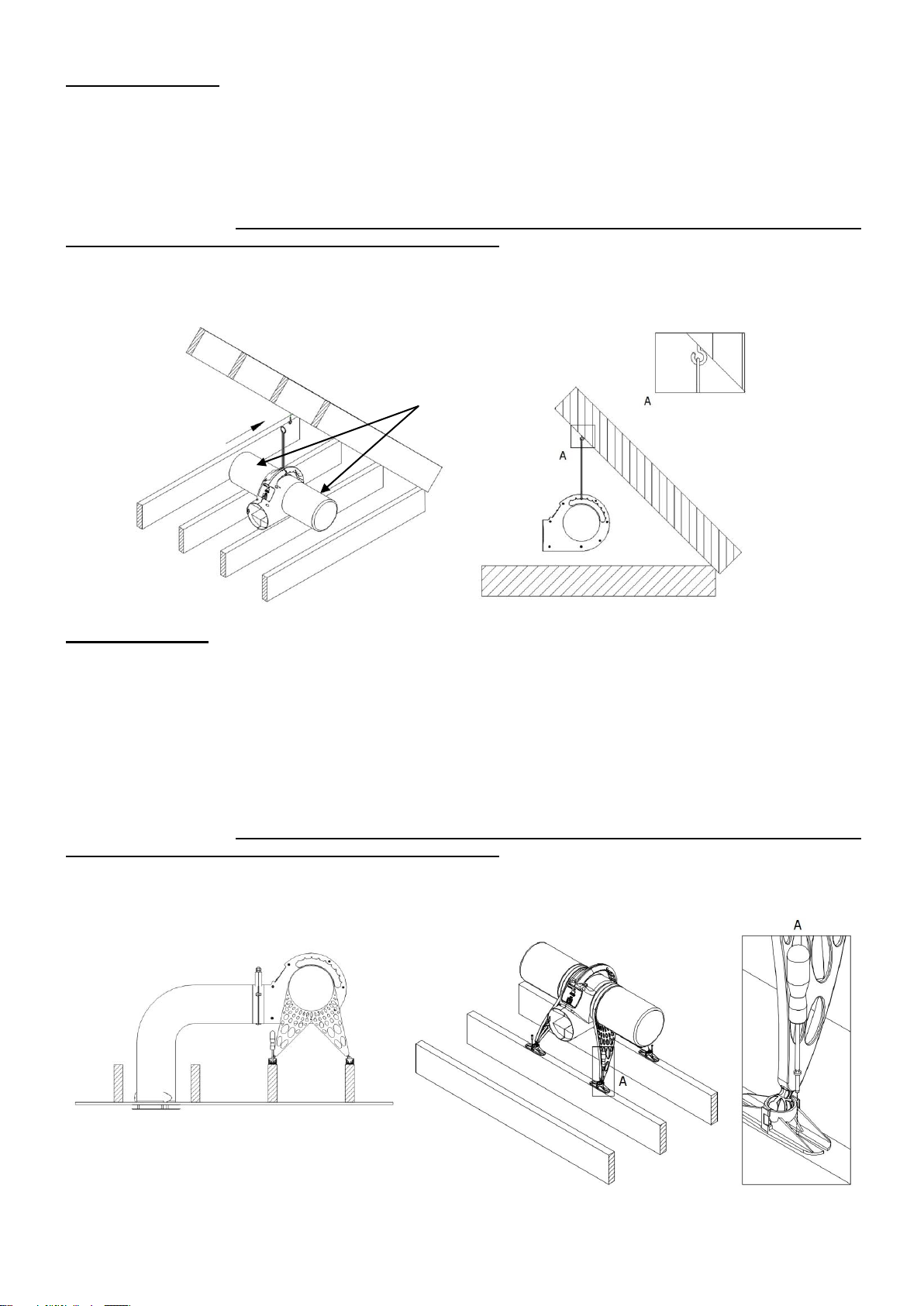
The Lo-Carbon PureAir Home can be hung from a roof beam (Fig. 2). Fix the screw eye to a convenient roof beam.
Use the cord provided to loop through the eye and around the handle on the unit, there are various notches for the
cord to run through, tie the two ends together using a suitable knot such as an over hand or fisherman’s knot.
Ensure that the route for the flexible ducting has gentle bends and that the duct cannot be crushed.
Fit the filters to the unit. Please make sure that the filters are fitted correctly. This will ensure that all the fresh
air entering the dwelling has passed through the filter first.
Ensure that the screw eye is attached to the beam strongly enough and that the beam is in sufficient
condition to withstand the load. The unit weight is approximately 4 kg.
Floor mounting:
Attach the mounting legs to the unit, two per side.
Find a suitable location to fix the unit near to where the diffuser is to be located. Ensure that the route for the flexible
ducting has gentle bends and that the duct cannot be crushed Fig.3.
The legs and feet can be adjusted to suit ceiling joists of varying spans. Adjust the legs and feet so that the unit
spans over two joists. Secure the feet to the joists with screws, Fig.4. In the unlikely event that the legs cannot span
the ceiling joists affix the unit to a wooden board or two lengths of timber which can then be screwed to the joists.
Fit the filters to the unit. Please make sure that the filters are fitted correctly. This will ensure that all the fresh
air entering the dwelling has passed through the filter first.
Page 5
5
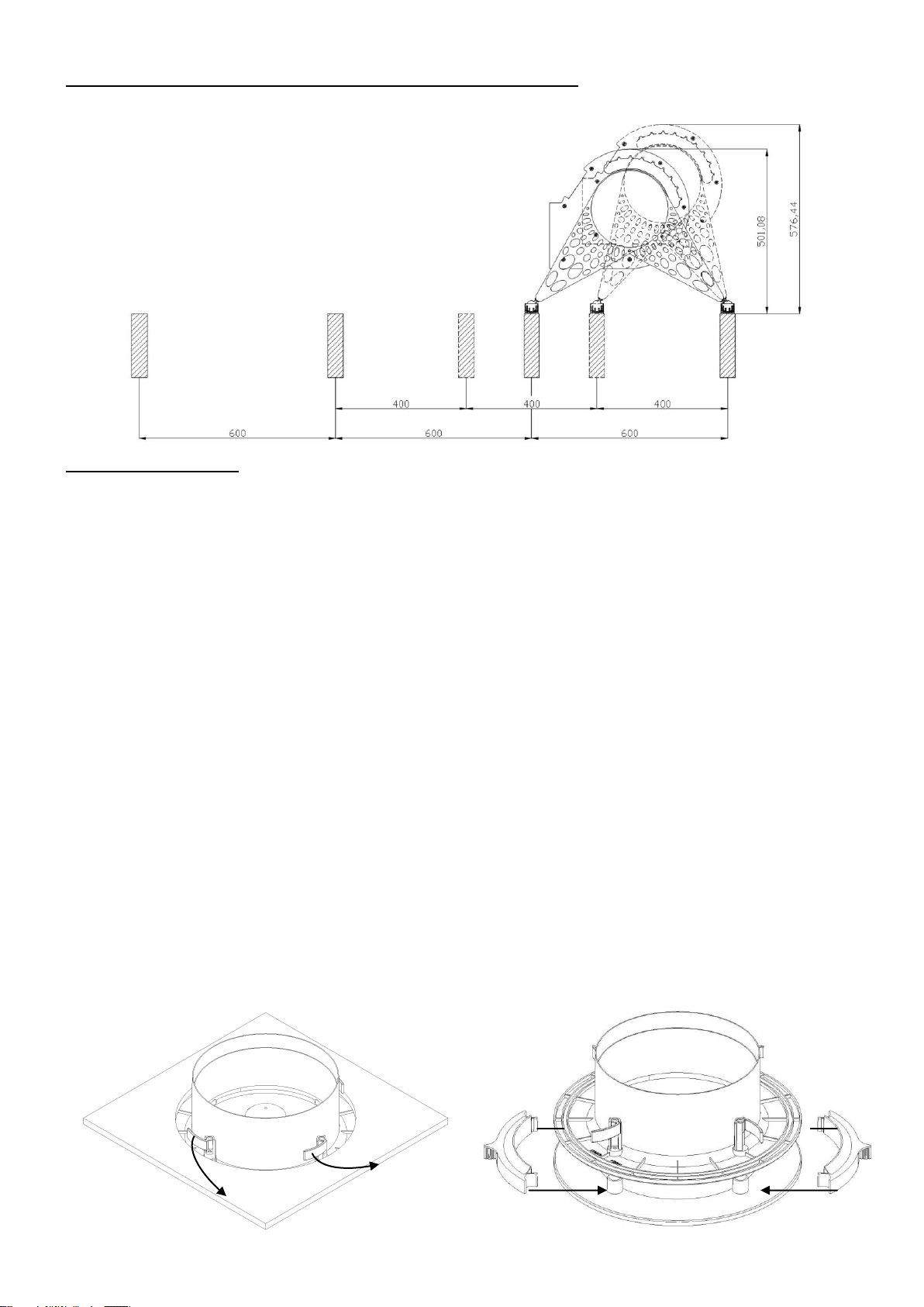
400-600mm Joist Dimensions with Unit Clearance Heights
Fig. 5.
Fig. 6.
DIFFUSER GRILLE:
IMPORTANT: PureAir Home FD models are provided with a different diffuser. Please follow instructions
provided with the diffuser for this model
The diffuser must be carefully sited to ensure the maximum effectiveness of the system. It should be fitted in the
ceiling of a common area, ideally above the landing so that the incoming air can reach all the rooms.
Cut the flexible ducting to a suitable length, where possible stretch the ducting to its maximum extent and ensure that
there is one continuous smooth bend to the diffuser. The ducting must remain a minimum of 1m in length.
Remove the loft insulation from the location of the diffuser and cut a 240-260mm dia hole in the ceiling.
Ensure the four locking tabs are folded in and then push the spigot in to the hole. Holding the diffuser in place; screw
the four screws until the locking tabs are holding the diffuser tight against the ceiling (Fig.5). It is important not to
over tighten these screws as this may warp the diffuser.
Fit the free end of the flexible ducting to the diffuser spigot using the worm drive clip supplied.
The diffuser should not be situated within 1m of a smoke detector, however if this is not possible the LoCarbon PureAir Home has provisions to blank off the airflow for up to two quadrants of the diffuser. Two
blanking plates are provided; these should be pushed on to the support struts inside the diffuser as
required. This should be done before the diffuser is installed in the ceiling as when the screws are tightened
down the plates can no longer be removed. See Fig.6, showing blocking off opposing quadrants, note any 1
or pair of quadrants can be blocked off as necessary for the install. These block off plates can also be used
to ensure the supply air is spread across a room rather than directed at close by walls.
Blanking off one side reduces the flow by about 6%, but blanking off two sides reduces the flow by about 20% and so
if two sides are blanked off then you should consider increasing the fan speed to maintain the appropriate airflow.
Page 6
6
PURE AIR
HOME UNIT
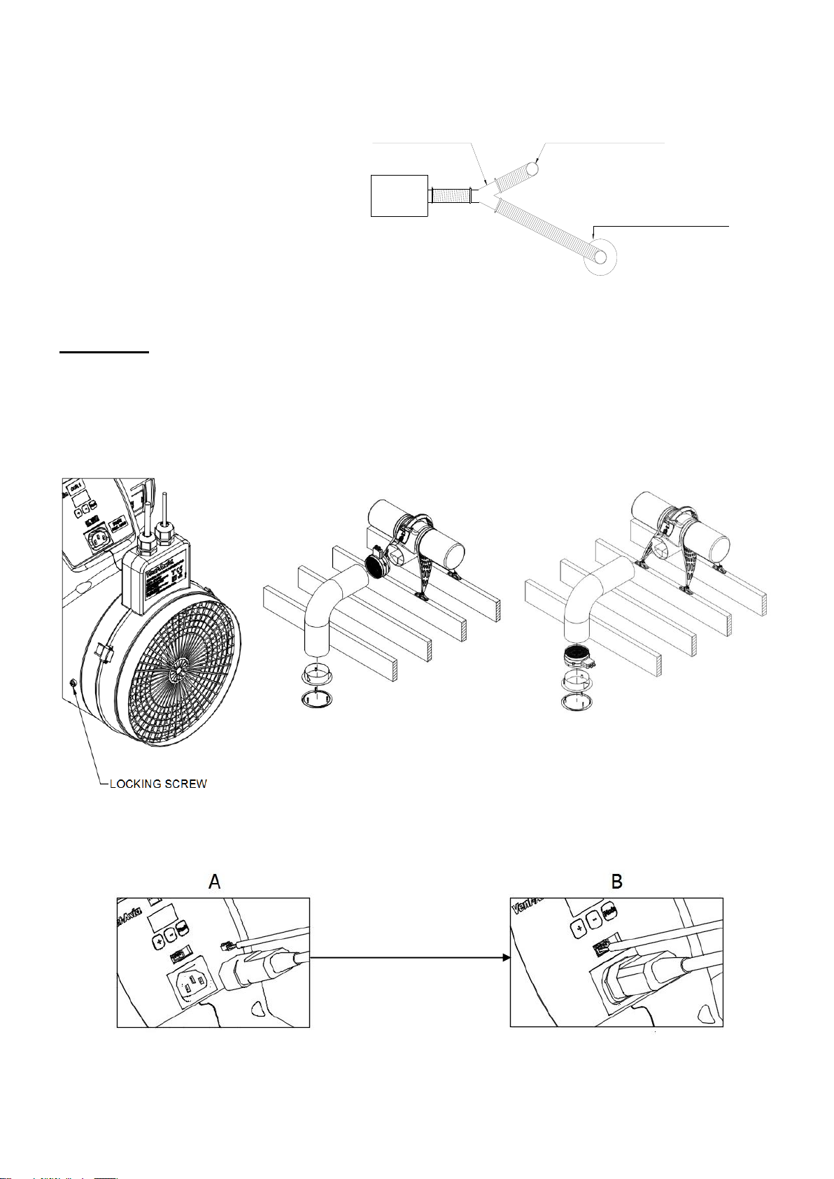
Y- PIECE SUPPLIED WITH
PIV TWIN SPIGOT KIT 449071
ROUND DIFFUSER SUPPLIED WITH
PIV TWIN SPIGOT KIT 449071.
(INSTALL NEAR UNIT)
ROUND DIFFUSER AS ABOVE
(SUPPLIED WITH PURE AIR HOME UNIT)
Fig. 8.
Fig. 7.
Unit Mounted
Diffuser Mounted
IMPORTANT
(Read only if installing with PIV
twin spigot kit Ref:- 449071)
Ensure that the adjustable diffuser
supplied with the kit is installed nearer
to the PureAir Home unit than the
round diffuser supplied with the unit.
This allows both flows to be balanced.
Not to be used with FD models
unless the diffuser supplied with
the kit is replaced with diffuser part 475664
Heater Unit
The heater unit can be mounted either to the unit or to the diffuser spigot see Fig. 7, where fitted to the unit there are
locating pins that fix the heater to the unit using a bayonet fitting and the locking screw. The power and sensor
cables must be plugged in to the front of the fan unit, see Fig 8.
Page 7
7
C. WIRING
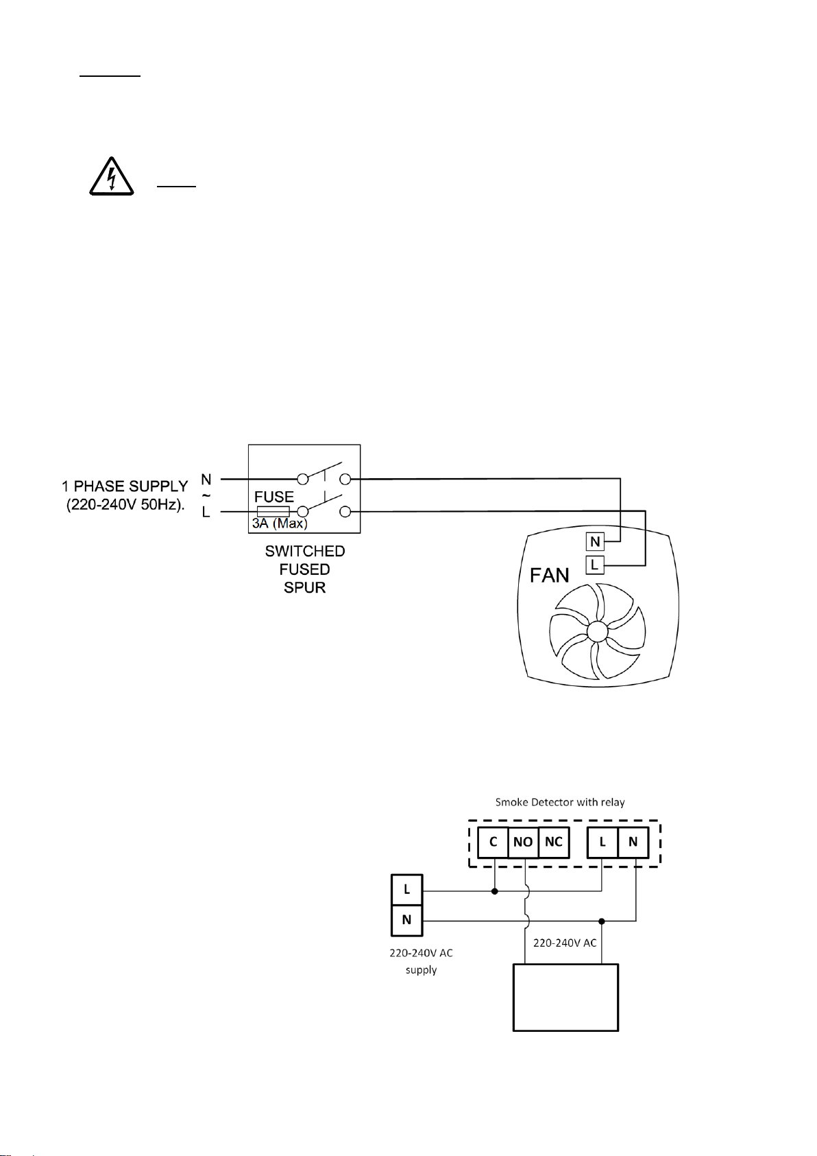
Fig.9
IMPORTANT:
PureAir Home FD models must be
installed with a smoke alarm with a relay
to ensure compliance with building
regulations.
In order to have the product switch off in the
event of a fire it must be wired using a smoke
alarm with a relay system.
Use Fig.9 as a reference and refer to the
instructions provided by the manufacturer
of the smoke alarm and relay in order to
wire the unit correctly. Ensure the relay
works correctly by testing the fire alarm;
the unit should switch off when the alarm
is sounding.
FOR REFERENCE ONLY
PureAir
Home Unit
A means for disconnection must be incorporated, in the fixed wiring in accordance with the wiring
regulations.
WARNING: THE POSITIVE VENTILATION UNIT AND ANCILLARY CONTROL EQUIPMENT
MUST BE ISOLATED FROM THE POWER SUPPLY DURING THE INSTALLATION / OR
MAINTENANCE.
Mains supply voltages (220-240V ac) are present in this equipment which may cause death or serious injury by
electric shock. Only a qualified electrician or installer should connect the power supply to this unit.
The Lo-Carbon PureAir Home is designed for operation from a single-phase alternating current source (220240V AC).
A 2 m integral mains flying lead is connected to the unit for connection to a 3A switched fused spur. It should be
capable of disconnecting all poles, having a contact separation of at least 3mm.
PureAir Home & PureAir Home with Heater unit:
Ensure the local AC power supply is isolated.
The product has a pre-wired flying lead. Connect the brown core to Live and the blue core to Neutral.
Use cable clamps and clips to secure the cable, as appropriate.
Page 8

8
D. START UP SEQUENCE
MODE
When the unit is switched on it will first run through a period of system checks. During this time the display will show
various system parameters before the fan motor starts. After 10 seconds the product will be ready for
commissioning.
E. COMMISSIONING
Accessing the Commissioning Menu
If the fan is powered and the display is not lit then press any button to access the menu. After 30 seconds without
menu activity the display will switch off, any changes to the settings will then be applied.
There are three buttons on the front of the unit:
The + button is used to increase the value of a setting, the – button is used to reduce the value of a setting and the
Mode button moves to the next menu item.
Lock feature
If the lock feature is enabled; when a button is pressed the display will show, – – –. At this point enter the
three digit code by first pressing + or – until the first digit is correct then press MODE to move to the next
digit. Repeat until the code is entered and press MODE to enter the commissioning menu. If the code is
entered incorrectly, wait until the screen switches off then press any button to begin again.
Page 9
9
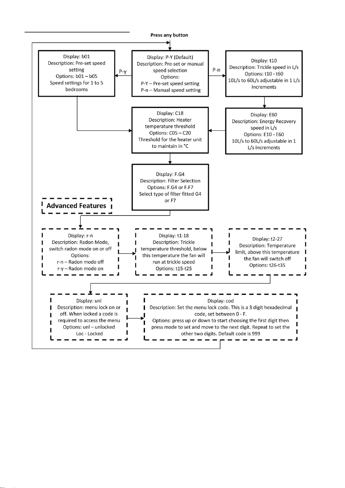
Commissioning Menu Structure
For most installs the standard features allow for ample adjustability, however in some install situations the advanced
features will improve the unit’s performance or acceptability.
Radon mode keeps the fan running even at high temperatures to prevent the build-up of dangerous radon gas in the
property. If this is not required it is recommended not to use this setting.
By reducing the trickle speed threshold the fan will run at higher speed more often, this would be helpful in a
property with persistent damp problems.
Increasing the temperature limit will mean the fan will continue to run at higher temperatures, note radon mode
being on means the unit will ignore this setting.
Page 10
10
The menu lock feature will prevent the unit from being adjusted after commissioning as a pass code is required to
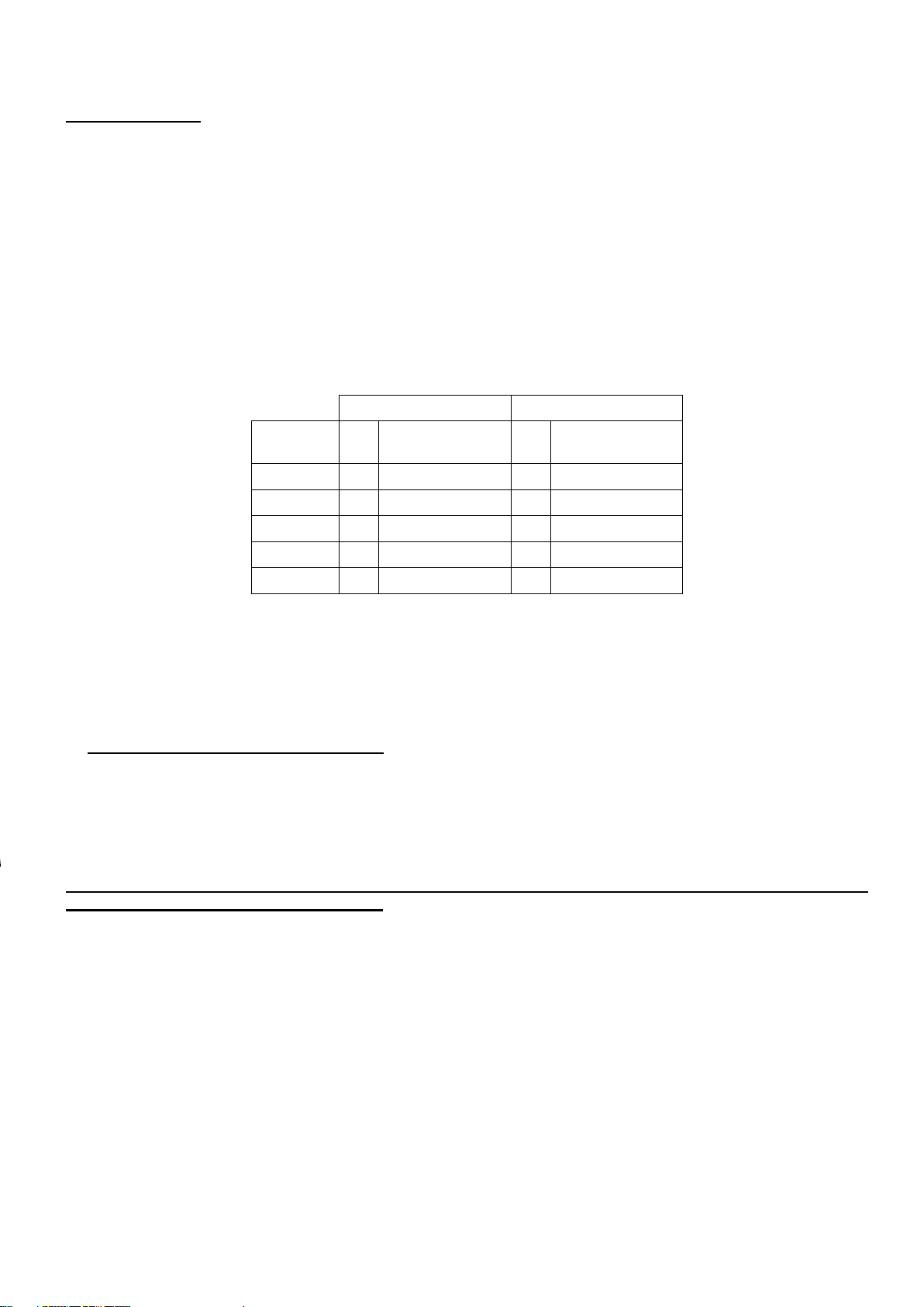
Fig.10
Trickle
Energy Recovery
No.
Bedrooms
L/s
Power (W)
L/s
Power (W)
1
13
2.2
25
3.6
2
17
2.6
31
4.8
3
21
3.2
38
5.5
4
25
3.6
44
7.5
5
29
4.3
50
11.5
access the menu. This can be set in the menu to any 3 digit hexadecimal combination.
Speed Settings
The Lo-Carbon PureAir Home has two speed settings, ‘Trickle’ and ‘Energy Recovery’.
‘Trickle’ speed is automatically selected when the ambient loft temperature is below 18°C.
‘Energy Recovery’ is automatically selected when the ambient loft temperature is between 18°C and 27°C.
If the ambient loft temperature exceeds 27°C, the Lo-Carbon PureAir Home automatically switches to standby (no
airflow).
The speed settings on the Lo-Carbon PureAir Home are fully adjustable between 10L/s and 60L/s via the manual
speed setting option. Alternatively there are 5 Pre-set speeds, the speed settings relate to the number of bedrooms
with, for example, setting b03 being for a three bedroom dwelling. For the approximate flow rates at each setting see
Fig.10. The PureAir Home must be set to provide adequate ventilation according to Part F of the building regulations.
The table shows a set up representative of a good low resistance install. When F7 filters and/or a long duct
run are used it may be necessary to use the manual speed selection to meet the required flow rate.
It is the responsibility of the installer to ensure that appropriate speeds are selected.
F. SERVICING AND MAINTENANCE.
The fan motor uses sealed ball bearings, and does not require further lubrication.
Apart from filter change the Lo-Carbon PureAir Home contains no user serviceable parts.
Under normal conditions; i.e. away from main roads and industrial areas it is recommended that the filter is checked
annually and cleaned or replaced as necessary. Otherwise change as required.
The filter may be gently cleaned with a vacuum cleaner or washed in a soapy water solution and allowed to air dry
before re-fitting. Do not dry the filter in a tumble dryer.
When re-fitting make sure that the filter is fitted correctly. This will ensure that all the fresh air entering the
dwelling has passed through the filter first.
Page 11

11
Below is a list of spares and accessories available for the PureAir Home:
Spares and Accessories
Part Number
F7 FILTER PACK
476401
HEATER UNIT
477626
1X REPLACEMENT MOUTNING LEG & FOOT
477627
HANGING KIT
477628
REPLACEMENT G4 FILTER PACK
477629
PIV TWIN SPIGOT KIT
449071
200mm DIAMETER 2m FLEXIBLE DUCTING
477748
REPLACEMENT DIFFUSER
477889
REPLACEMENT DIFFUSER FOR FD MODEL
475664
REPLACEMENT MOUNTING FOOT
478000
DIFFUSER ASSEMBY
478228
REPLACEMENT FOOT PACK
478000
Name:
Vent-Axia
Vent-Axia
Vent-Axia
Model ID (Stock Ref.) :
Lo-Carbon PureAir
Home - 479090
Lo-Carbon PureAir
Home - 479091
Lo-Carbon PureAir
Home- 479092
SEC Class B B
B
SEC Value ('Average')
28.30
28.30
28.30
SEC Value ('Warm')
12.80
12.80
12.80
SEC Value ('Cold')
55.36
55.36
55.36
Label Required? (Yes/No=Out of scope)
No
No
No
Declared as: RVU or NRVU/UVU or BVU
RVU-UVU
RVU-UVU
RVU-UVU
Speed Drive
Variable Speed
Variable Speed
Variable Speed
Type HRS (Recuperative, Regenerative, None)
None
None
None
Thermal Eff: [ (%), NA(if none)]
N/A
N/A
N/A
Max. Flow Rate (m3/h)
198.00
198.00
198.00
Max. Power Input (W): (@Max.Flow Rate)
14.00
14.00
14.00
LWA: Sound Power Level (dB)
35.53
35.53
35.53
Ref. Flow Rate (m3/s)
0.04
0.04
0.04
Ref. Pressure Diff. (Pa)
N/A
N/A
N/A
SPI [W/(m3/h)]
0.09
0.09
0.09
Control Factor & Control Typology: (CTRL/ Typology)
Control Factor; CTRL
0.65
0.65
0.65
Control Typology
Local Demand Control
Local Demand Control
Local Demand Control
Declared: -Max Internal & External Leakage Rates(%) for BVUs or
carry over (for regenerative heat exchangers only),
-&Ext. Leakage Rates (%) for Ducted UVUs;
N/A
N/A
N/A
Mixing Rate of Non-Ducted BVUs not intended to be equipped with
one duct connection on either supply or extract air side;
N/A
N/A
N/A
Position and description of visual filter warning for RVUs intended
for use with filters, including text pointing out the importance of
regular filter changes for performance and energy efficiency of the
unit
N/A
N/A
N/A
For UVUs (Instructions Install Regulated Supply/Extract Grilles
Façade)
In F&W
In F&W
In F&W
Internet Address (for Disassembly Instructions)
www.vent-axia.com
www.vent-axia.com
www.vent-axia.com
Sensitivity p. Variation@+20/-20 Pa: (for Non-Ducted Vus)
N/A
N/A
N/A
Air Tightness-ID/OD-(m3/h) (for Non-Ducted Vus)
N/A
N/A
N/A
Annual Electricity Consumption: AEC (kWh/a)
0.46
0.46
0.46
Annual Heating Saved: AHS (kWh/a)
AHS: Average
28.30
28.30
28.30
AHS: Warm
12.80
12.80
12.80
AHS: Cold
55.36
55.36
55.36
PRODUCT FICHE
For Residential Ventilation Units (Complying Commission Delegated Regulation (EU) No 1254/2014)
Page 12
12
Head Office: Fleming Way, Crawley, West Sussex, RH10 9YX.
UK NATIONAL CALL CENTRE, Newton Road, Crawley, West Sussex, RH10 9JA
SALES ENQUIRIES: Tel: 0344 8560590 Fax: 01293 565169
TECHNICAL SUPPORT: Tel: 0344 8560594 Fax: 01293 532814
For details of the warranty and returns procedure please refer to www.vent-axia.com or write to Vent-Axia, Fleming
Way, Crawley, RH10 9YX
479369 B 0319
The Guarantee
Applicable only to products installed and used in the United Kingdom. For details of guarantee outside the United Kingdom contact your local
supplier.
Vent-Axia guarantees its products for five years from date of purchase against faulty material or workmanship. In the event of any part being
found to be defective, the product will be repaired, or at the Company’s option replaced, without charge, provided that the product:-
Has been installed and used in accordance with the instructions given with each unit.
Has not been connected to an unsuitable electricity supply. (The correct electricity supply voltage is shown on the product rating
label attached to the unit).
Has not been subjected to misuse, neglect or damage.
Has not been modified or repaired by any person not authorised by the company.
IF CLAIMING UNDER TERMS OF GUARANTEE
Please return the complete product, carriage paid to your original supplier or nearest Vent-Axia Centre, by post or personal visit. Please ensure
that it is adequately packed and accompanied by a letter clearly marked “Guarantee Claim” stating the nature of the fault and providing
evidence of date and source of purchase.
Disposal
This product should not be disposed of with household waste. Please recycle where facilities exist. Check
with your local authority for recycling advice.
 Loading...