

Page 1
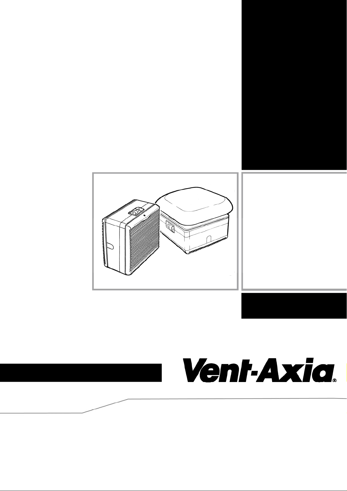
Lo-Carbon
T-series
Window & Roof Models
Installation & User Instructions
WIRED
456165A (9” WW)
456168A (9” RF)
456173A (12” WW)
456176A (12” RF)
WIRELESS
456169A (9”WW)
456172A (9” RF)
456177A (12” WW)
456180A (12” RF)
READ INSTRUCTIONS IN CONJUNCTION WITH THE ILLUSTRATIONS
Page 2
IMPORTANT
1. THE FAN MUST BE SITED AND CONNECTED IN ACCORDANCE WITH CURRENT IEE REGULATIONS (UK) OR
THE APPROPRIATE STANDARDS IN YOUR COUNTRY.
2. THIS APPLIANCE IS NOT SUITABLE FOR INSTALLATION IN A SHOWER CUBICLE OR ENCLOSURE AND MUST
BE SITED AWAY FROM ANY SOURCE OF WATER SPRAY, AND MUST BE OUT OF REACH OF A PERSON
USING A FIXED BATH OR SHOWER.
3. SITE AWAY FROM DIRECT SOURCES OF HEAT IN EXCESS OF 50ºC OR LESS THAN –10ºC.
4. WHEN THE FAN IS USED TO REMOVE AIR FROM A ROOM CONTAINING A FUEL-BURNING APPLIANCE,
PRECAUTIONS MUST BE TAKEN TO AVOID BACK-FLOW OF GASES INTO THE ROOM FROM THE OPEN FLUE
OF GAS OR OTHER APPLIANCE. ENSURE THAT THE AIR REPLACEMENT IS ADEQUATE FOR BOTH THE FAN
AND THE FUEL-BURNING APPLIANCE.
5. IT IS RECOMMENDED THAT THE CONNECTION TO THE CONNECTOR SOCKET IS MADE WITH FLEXIBLE
CABLE FOR EASY MAINTENANCE.
6. WIRING SHOULD BE VIA A SWITCHED SPUR WITH A 3 AMP FUSE (UK ONLY).
7. DOUBLE POLE SWITCH WITH A MINIMUM CONTACT SEPARATION OF 3MM OR PLUG AND SOCKET SHOULD
BE LOCATED OUTSIDE OF A ROOM CONTAINING A FIXED BATH OR SHOWER.
8. THIS APPLIANCE MUST BE EARTHED.
9. READ THESE INSTRUCTIONS FULLY BEFORE COMMENCING INSTALLATION.
10. THE APPLIANCE IS NOT INTENDED FOR USE BY PERSONS (INCLUDING CHILDREN) WITH REDUCED
PHYSICAL, SENSORY OR MENTAL CAPABILITIES, OR LACK OF EXPERIENCE AND KNOWLEDGE, UNLESS
THEY HAVE BEEN GIVEN SUPERVISION OR INSTRUCTION CONCERNING USE OF THE APPLIANCE BY A
PERSON RESPONSIBLE FOR THEIR SAFETY.
11. YOUNG CHILDREN SHOULD BE SUPERVISED TO ENSURE THAT THEY DO NOT PLAY WITH THE APPLIANCE.
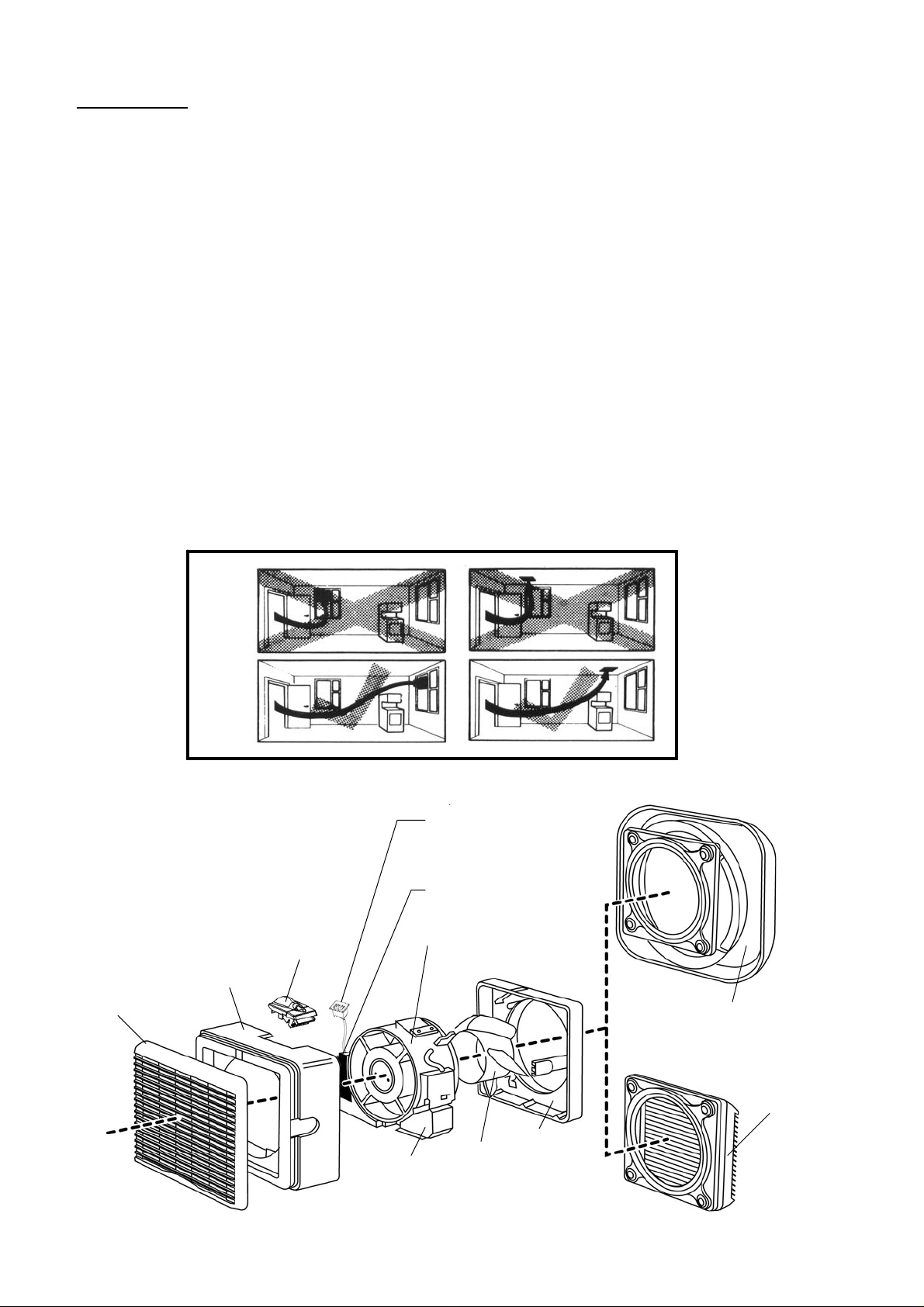
12. A SHORT CIRCUIT OF THE AIR FLOW SHOULD ALWAYS BE AVOIDED BY SITING THE FAN AS FAR AWAY AS
POSSIBLE FROM AND OPPOSITE TO THE MAIN SOURCE OF AIR REPLACEMENT. B1/ 2
Fig. 1
INDOOR GRILLE
B1/ 2
HOUSING
CONNECTOR
SOCKET
SPEED CONTROLLER
CONNECTION SOCKET
(WIRED VERSION ONLY)
POWER SUPPLY/
RECEIVER UNIT
MOTOR BODY HOUSING
ROOF COWL
OUTER GRILLE
SECTION
BASE
IMPELLER
SHUTTER
ACTUATOR
2
Page 3
FAN DIMENSIONS
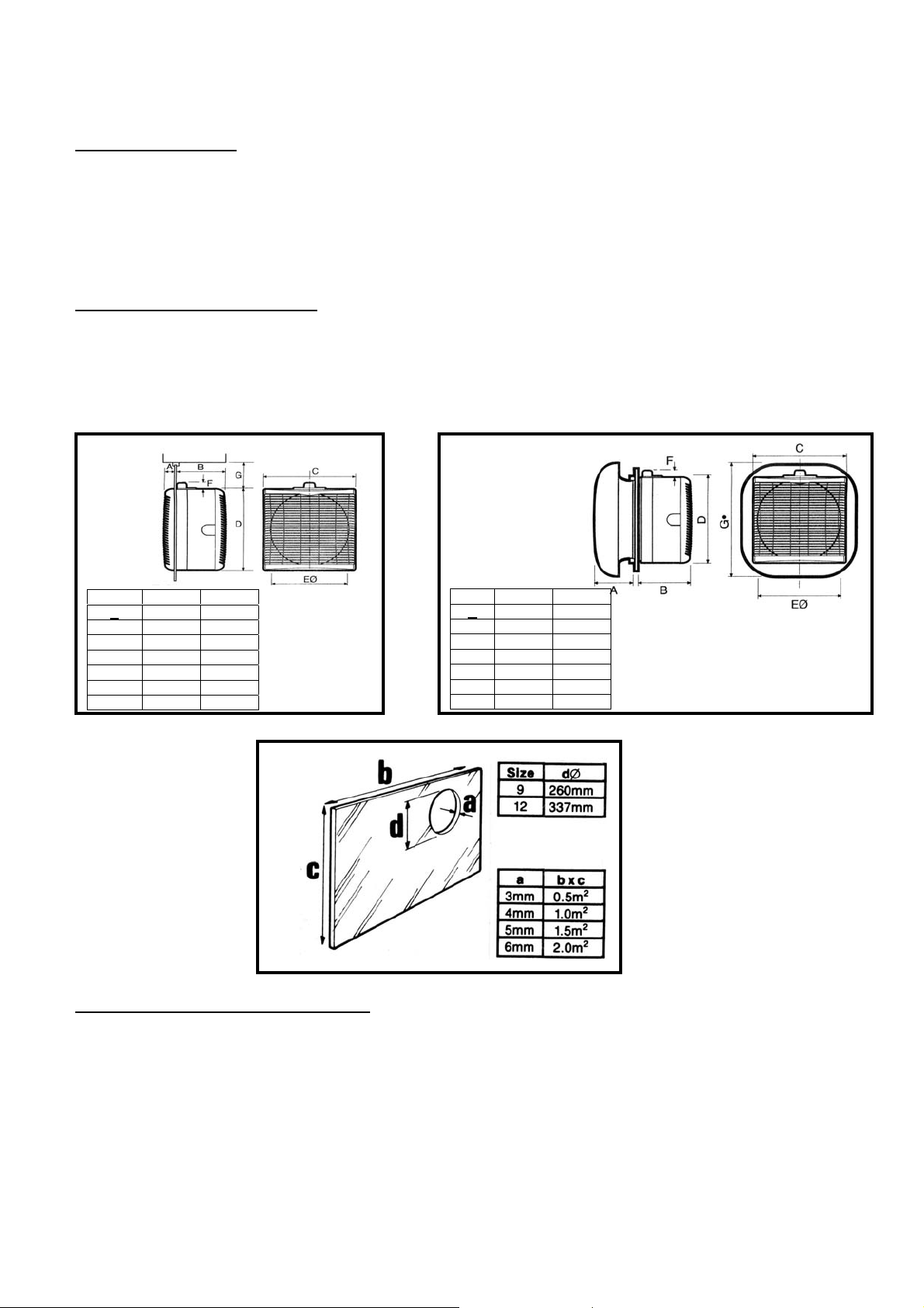
Before commencing work, study the tables shown in figures C1/ C2 to ensure fan will fit in position
proposed. NB: Allow a minimum of 54mm above fan casing for withdrawal of connector socket.
• Please note that for all Roof Fan installations a suitable sealing compound must be used to
seal the exterior roof cowl assembly to the glass/or roof plate, to ensure a weatherproof seal.
D1 THICKNESS OF GLASS
Fans can be fitted in most types of glass and fixing thickness up to 32mm, with the screws provided.
When fixing thickness exceeds 32mm, the unit should be secured with Extended Fixing Rods. If the
unit is to be installed in a location exposed to severe wind turbulence or in non-vertical panes, thicker
glass will be required – consult your nearest Vent-Axia Sales, Service and Distribution Centre.
C1 C2
SIZE 9 12
A 39mm 41mm
B 150mm 177mm
C 304mm 381mm
D 302mm 378mm
EØ 260mm 337mm
F 20mm 20mm
G 54mm 54mm
PREPARATION FOR INSTALLATION
E1 Place fan unit, impeller downwards, on a flat surface. Unscrew the grille-securing screw located
at the top of the grille.
E2 Remove grille. Partially unscrew the two safety catch screws on the face of the housing
E3 Depress the side catches.
E4 Lift off the housing.
E5 Release the Power Supply/Receiver Unit catch, located at the bottom left of the motor body
housing assembly.
E5a Lift the Power Supply/ Receiver Unit until the second catch engages. Slide the speed controller
connection socket from the housing (wired version only).
D1
SIZE 9 12
A 136mm 171mm
B 150mm 177mm
C 304mm 381mm
D 302mm 378mm
EØ 260mm 337mm
F 20mm 20mm
G 400mm 500mm
3
Page 4
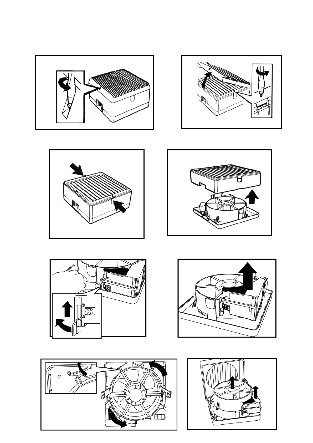
E6 Ease back the motor support safety catch, located to the left of the connector socket opening.
Rotate motor body housing anti-clockwise until the bayonet catch disengages.
E7 Withdraw motor body housing and place with the impeller downwards.
E1
E2
E3
E4
E5
E5a
E6
4
E7
Page 5
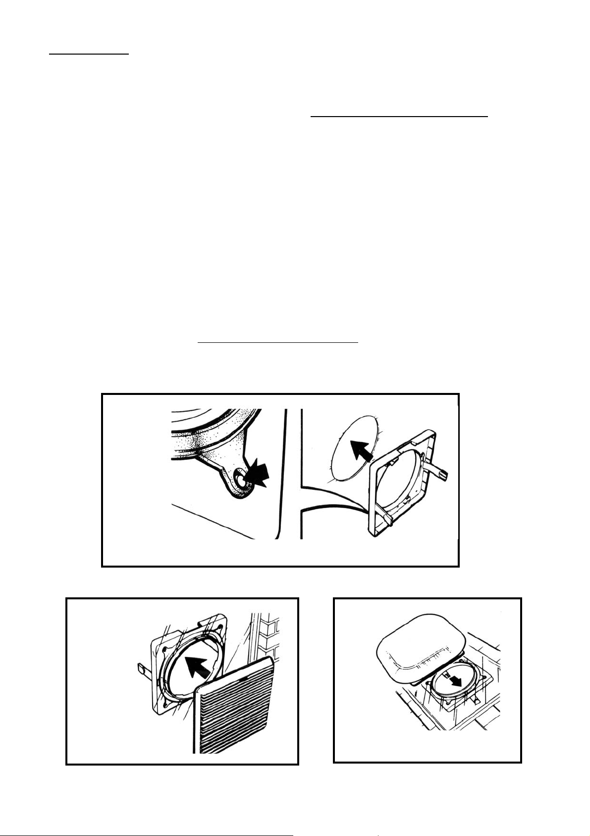
INSTALLATION
F1 From the inside: Fit the spigot through the fixing hole, with the connector socket cut out at the
top. Ensure that the rubber seal is correctly located over the four lugs on the spigot.
F2i WINDOW
From outside: Place the outdoor grille assembly with the louvres slanting downwards,
Vent-Axia logo at the top of the grille, over the projecting spigot.
F2ii ROOF
From outside: Place the exterior roof cowl over the projecting spigot. Use a suitable sealing
compound between the cowl and the glass/or roof plate.
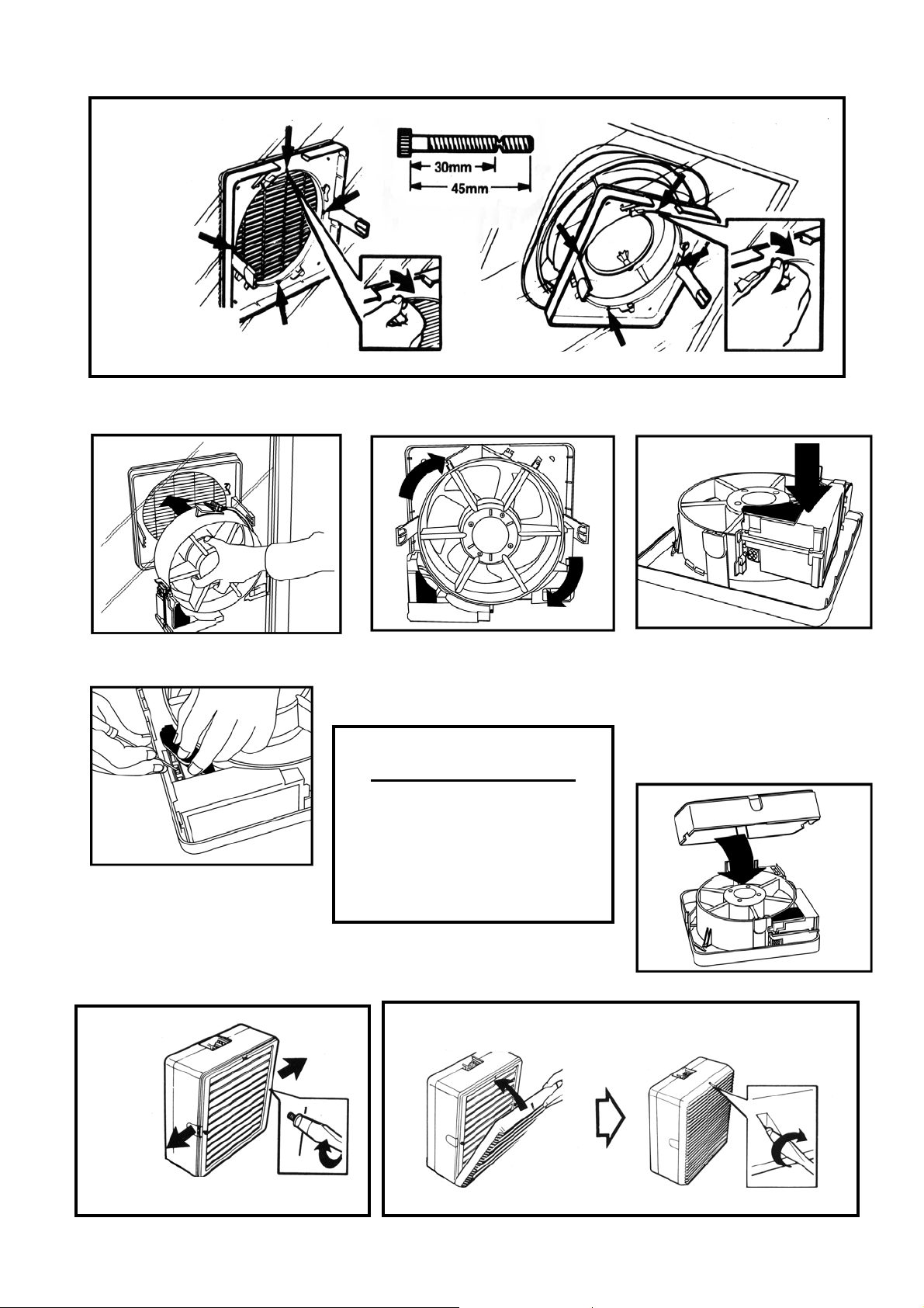
F3i/ ii Secure the outdoor grille or roof cowl, using the fixing screws supplied. Then tighten the
screws in turn to give an even pressure around the hole.
F4a/ b Refit the motor body housing assembly and turn clockwise until the locking catch is engaged.
Take care not to trap the mains supply cable or the speed controller socket cable (wired version
only).
F5 Release the Power Supply/Receiver Unit locking catch and lower until the catch engages in the
lower position, fix the controller socket into position (wired version only).
F6 Lift the black rubber gasket on the Power Supply/Receiver Unit and switch the three-position
switch to the required running option, then replace the gasket seal.
F7 If a speed controller is being used refer to the relevant Speed Controller Fitting and Wiring
instructions.
F8 Refit the housing ensuring that no internal wires are trapped between the housing and base.
F9 Engage the two side catches. Tighten the two side catch screws.
F10 Replace the indoor grille with the louvres slanting upwards
bottom of the grille, and secure with the retaining screw.
F2i
F1
, with the Vent-Axia logo at the
F2ii
and the
5
Page 6
F3i/ ii
F4a
F6
F5
F4b
F7
FOR SPEED CONTROL
REFER TO THE RELEVANT
FITTING AND WIRING
INSTRUCTIONS SUPPLIED WITH
THE WIRED/ WIRELESS
CONTROL.
F8
F9 F10
6
Page 7
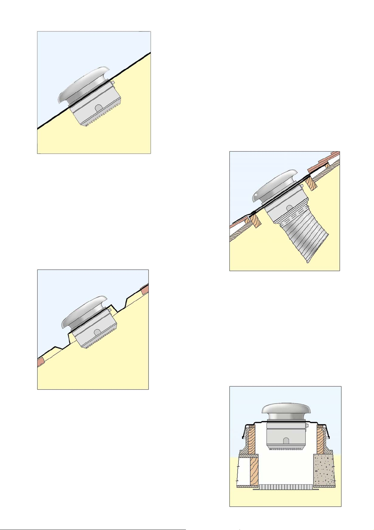
TYPICAL ROOF INSTALLATIONS USING VENT-AXIA ACCESSORIES
A
(A) ROOF LIGHT
All T-Series roof models are designed to fit directly
into horizontal and sloping glass including wired cast
and sealed double glazing up to 32mm thick. For
materials of greater thicknesses extended fixing rod
sets are available, allowing the unit to be fixed
through a spacing of up to 370mm.
Rod thread: 3.5mm
Maximum fixing thickness: 370mm
(B) PITCHED ROOF
All T-Series roof models may be installed in fixing
plates with zinc or lead weathering apron (provided by
others), fitted directly to a tiled or slated roof to
provide a water-tight installation. A suitable sealing
compound should be used between the
weathering apron and the exterior unit seal
The illustration shows a T-Series roof model fitted with
a direct mount spigot and flexible ducting.
C
(C) CORRUGATED ROOF
All T-Series roof models are suitable for fixing through
corrugated sloped and vertical cladding using a
suitable soaker flange. The soaker flange consists of
a replacement sheet with a flat section to carry the
unit.
A suitable sealing compound should be used between
the plate and the exterior unit seal.
(D) FLAT ROOF
All T-Series roof models may be installed through
solid roofs using a roof plate assembly and, if
required, an eggcrate grille or louvred grille in the
ceiling below. Alternatively, if ventilation is from a
suspended ceiling, single spigots and flexible ducting
may be used to connect the unit and extract grille.
Roof plate assemblies are manufactured in high
impact thermoplastic. A suitable sealing compound
should be used between the plate and exterior unit
seal.
B
D
7
Page 8
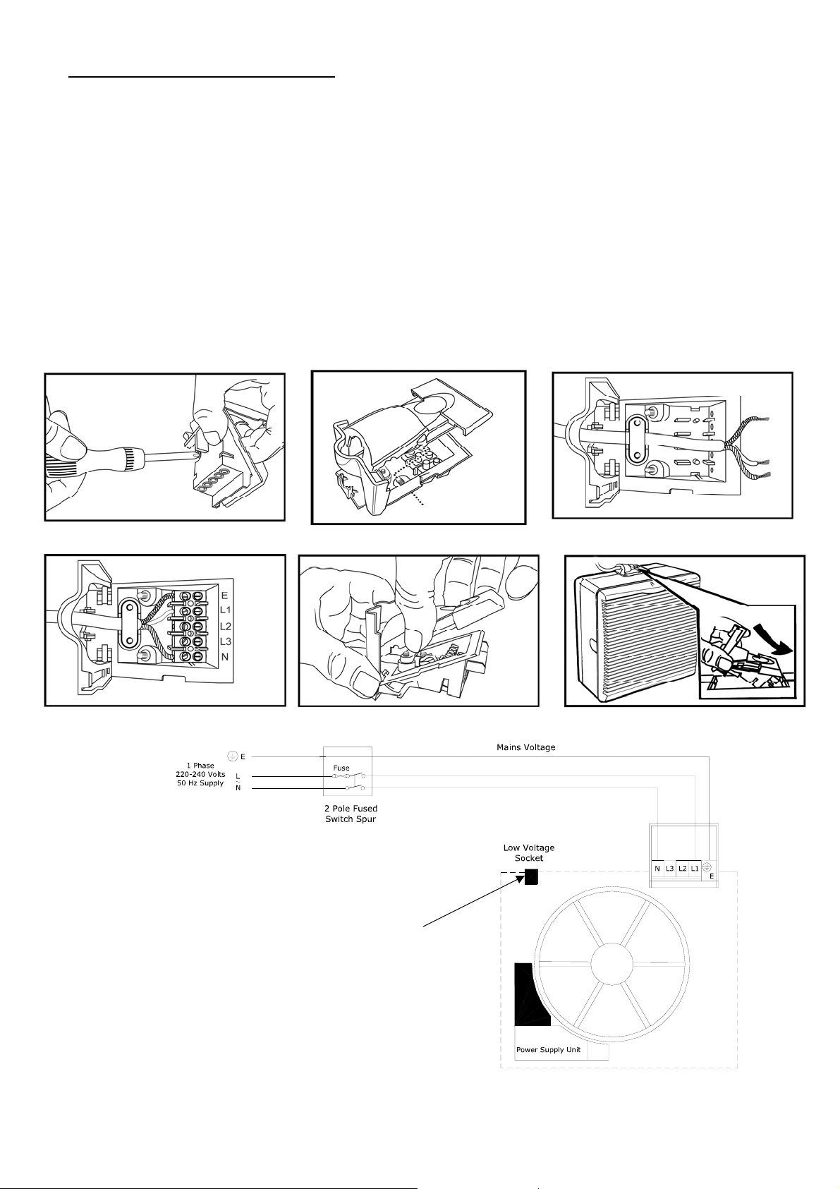
WIRING THE CONNECTOR SOCKET
• Ensure that the supply (Voltage, Frequency and Phase) complies with the rating label.
• This appliance must be earthed.
F11 Remove the top cover from the connector socket by undoing the 2 retaining screws.
F12 Lift up lever and slide out top cover.
F13 Loosen cable clamp screws and pass the cable through the clamp. (It may be necessary when
using some 3-core cables to reverse the cable clamp to ensure that the cable is securely
retained. For ease of wiring, the terminal block may be removed from the connector housing.
F14 Tighten cable clamp screws evenly, ensuring a secure grip on the outer sheath of the cable.
F15 Slide the top cover back on and secure with the 2 retaining screws.
F16 Fit connector socket and push down on the lever to lock it in position.
Fig 2 Using an On/Off switch: Connect the mains supply to the fan connector socket.
Fig 3 Auxiliary sensor switching: Connect the mains supply to the fan connector socket.
F11
F12
F14
F15
Fig. 2
T-Series Lo-carbon
Connection socket
(Wired version only)
Please refer also to the speed controller
fitting and wiring instructions.
F13
F16
8
Page 9
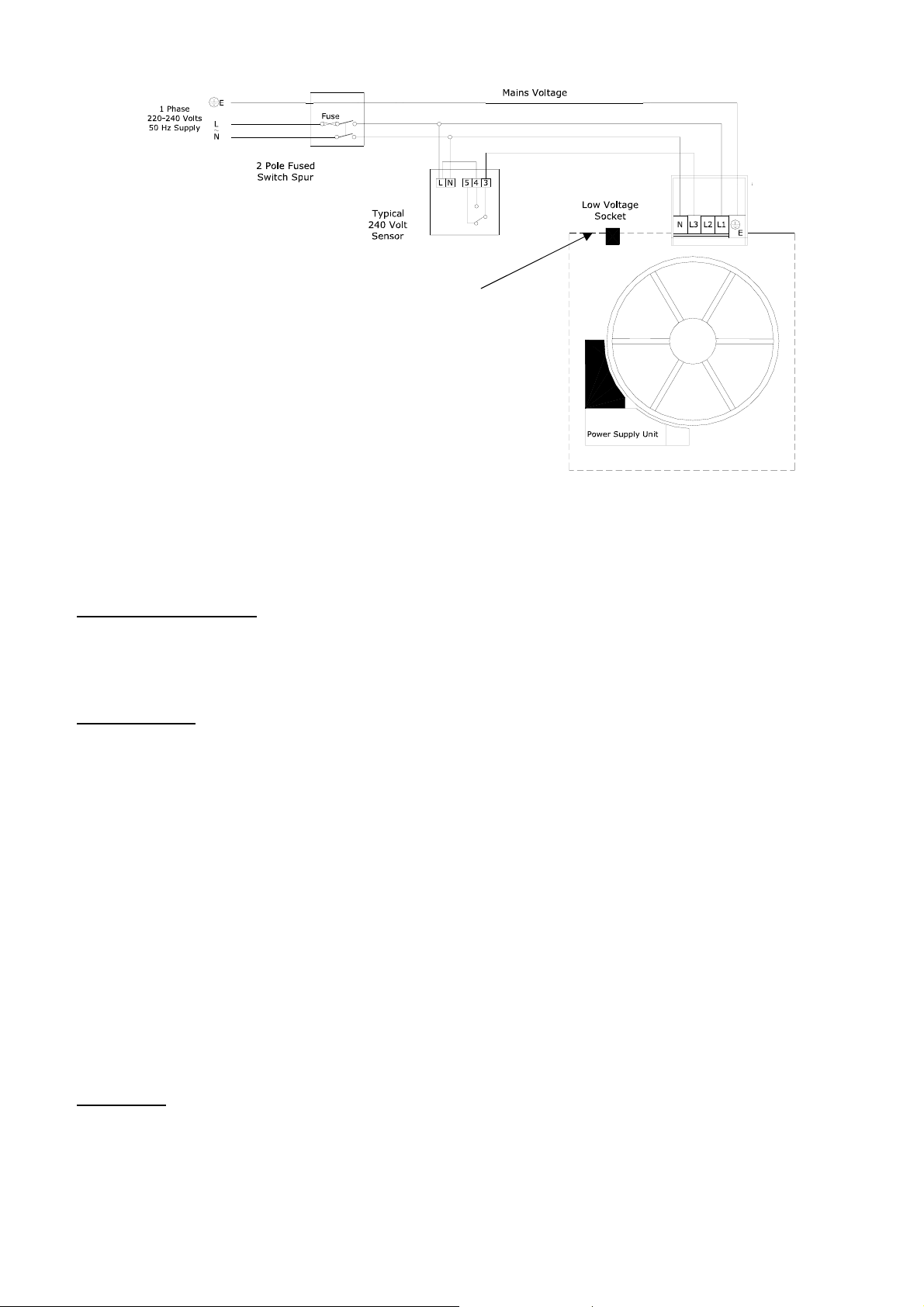
Fig. 3
(Wired version only)
Please refer also to the speed controller
fitting and wiring instructions.
T-Series Lo-carbon
Connection socket
ISOLATE FROM THE POWER SUPPLY PRIOR TO ANY MAINTENANCE AND CLEANING
USER INSTRUCTIONS
• At intervals appropriate to the installation, inspect and clean the fan to ensure there is no build up
of grease or dirt on the impeller or the motor.
• The motor is fitted with sealed for life bearings and does not require lubrication.
DISMANTLING
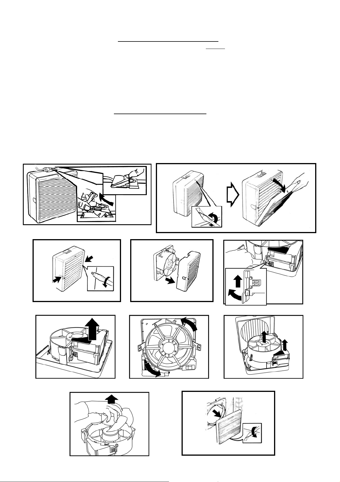
G1 From the inside, remove the connector socket by lifting up the lever gently with a finger, unplug
the controller cable (wired version only).
G2 Unscrew the indoor grille retaining screw and remove the grille.
G3 Partially unscrew the two side catch screws on the housing and depress the two side catches.
G4 Remove the housing.
G5a Release the Power Supply/Receiver Unit catch, located at the bottom left of the motor body
housing assembly.
G5b Lift the Power Supply/Receiver Unit until the second catch engages. Slide the controller socket
from the housing (wired version only).
G6 Release the motor body housing assembly locking catch located to the left of the connection
socket opening and rotate the motor body housing assembly anti-clockwise until the bayonet
catches disengage.
G7 Withdraw the motor body housing assembly and put to one side, with the impeller facing
upwards.
G8 Remove the impeller with a sharp pull away from the motor.
G9 Unscrew the outdoor grille retaining screw and remove the grille.
CLEANING
IMPORTANT: Keep all electrical components away from water.
G10 Wipe the motor, housing assembly and roof cowl (if fitted) with a damp cloth.
G11 Wash all non-electrical components in warm water and detergent.
9
Page 10
REASSEMBLY - ALLOW THE COMPONENTS TO DRY BEFORE REASSEMBLY
G12 Replace the outdoor grille with the louvres slanting downwards
top of the grille. Tighten the retaining screw located at the bottom
, and the Vent-Axia logo at the
of the grille.
G13 Align the impeller with the locating pins on the motor shaft and refit the impeller with a sharp
push.
G14a/b Refit the motor body housing assembly and turn clockwise until the locking catch is engaged.
Take care not to trap the speed controller socket cable (wired version only).
G15 Release the Power Supply/Receiver Unit locking catch and lower until the catch engages in the
lower position, fix the controller socket into position (wired version only).
G16 Refit the housing ensuring that no internal wires are trapped between the housing and base.
G17 Engage the two side catches. Tighten the two side catch screws.
G18 Replace the indoor grille with the louvres slanting upwards
and the Vent-Axia logo at the bottom
of the grille, then secure with the retaining screw.
G19 Replace the connector socket, push firmly into position and press the black locking peg down
flush with the top of the connector socket. Plug the controller cable connector into the socket
(wired version only).
RECONNECT THE MAINS SUPPLY AND SWITCH THE UNIT ON.
G3 G4
G1
G5b
G8
G2
G6
G5a
G7
G9
10
Page 11
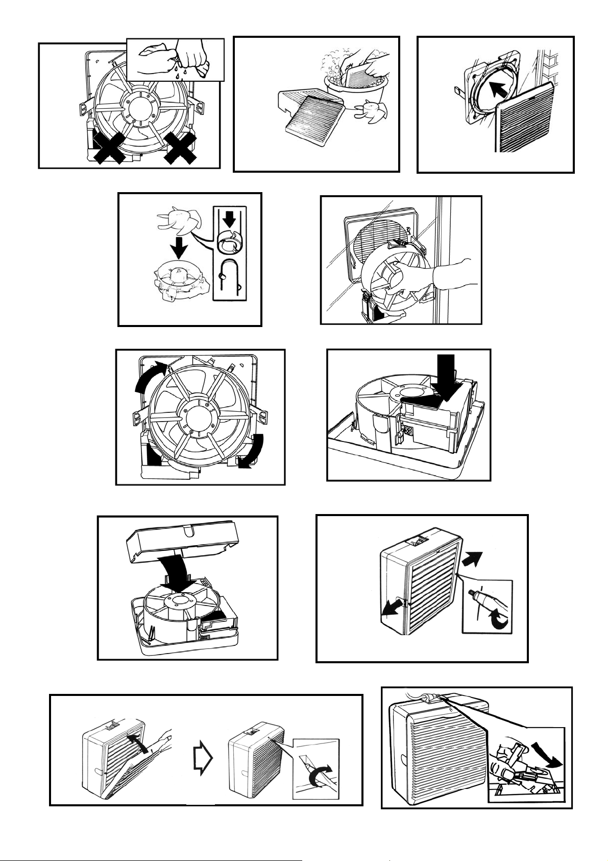
G10
G18
G11
G13
G14b
G16
G14a
G15
G17
G12
G19
11
Page 12
The abc Guarantee
Applicable only to products installed and used in the United Kingdom. For details of guarantee outside the United Kingdom contact your local
Vent-Axia guarantees its products for two years from date of purchase against faulty material or workmanship. In the event of any part being found
to be defective, the product will be repaired, or at the Company’s option replaced, without charge, provided that the product:-
• Has been installed and used in accordance with the instructions given with each unit.
• Has not been connected to an unsuitable electricity supply. (The correct electricity supply voltage is shown on the product rating label
attached to the unit).
• Has not been subjected to misuse, neglect or damage.
• Has not been modified or repaired by any person not authorised by the company.
IF CLAIMING UNDER TERMS OF GUARANTEE
Please return the complete product, carriage paid to your original supplier or nearest Vent-Axia Centre, by post or personal visit. Please ensure
that it is adequately packed and accompanied by a letter clearly marked “Guarantee Claim” stating the nature of the fault and providing evidence of
date and source of purchase.
The guarantee is offered to you as an extra benefit, and does not effect your legal rights
supplier.
Head Office: Fleming Way, Crawley, West Sussex, RH10 9YX. Tel: 01293 526062 Fax: 01293 551188
UK NATIONAL CALL CENTRE, Newton Road, Crawley, West Sussex, RH1 0 9JA
SALES ENQUIRIES: Tel: 0844 8560590 Fax: 01293 565169
TECHNICAL SUPPORT: Tel: 0844 8560594 Fax: 01293 539209
For details of the warranty and returns procedure please refer to www.vent-ax ia.com or write to Vent-Axia Ltd, Fleming Way, Crawley, RH10 9YX
428208E 1210
12
 Loading...