

Page 1
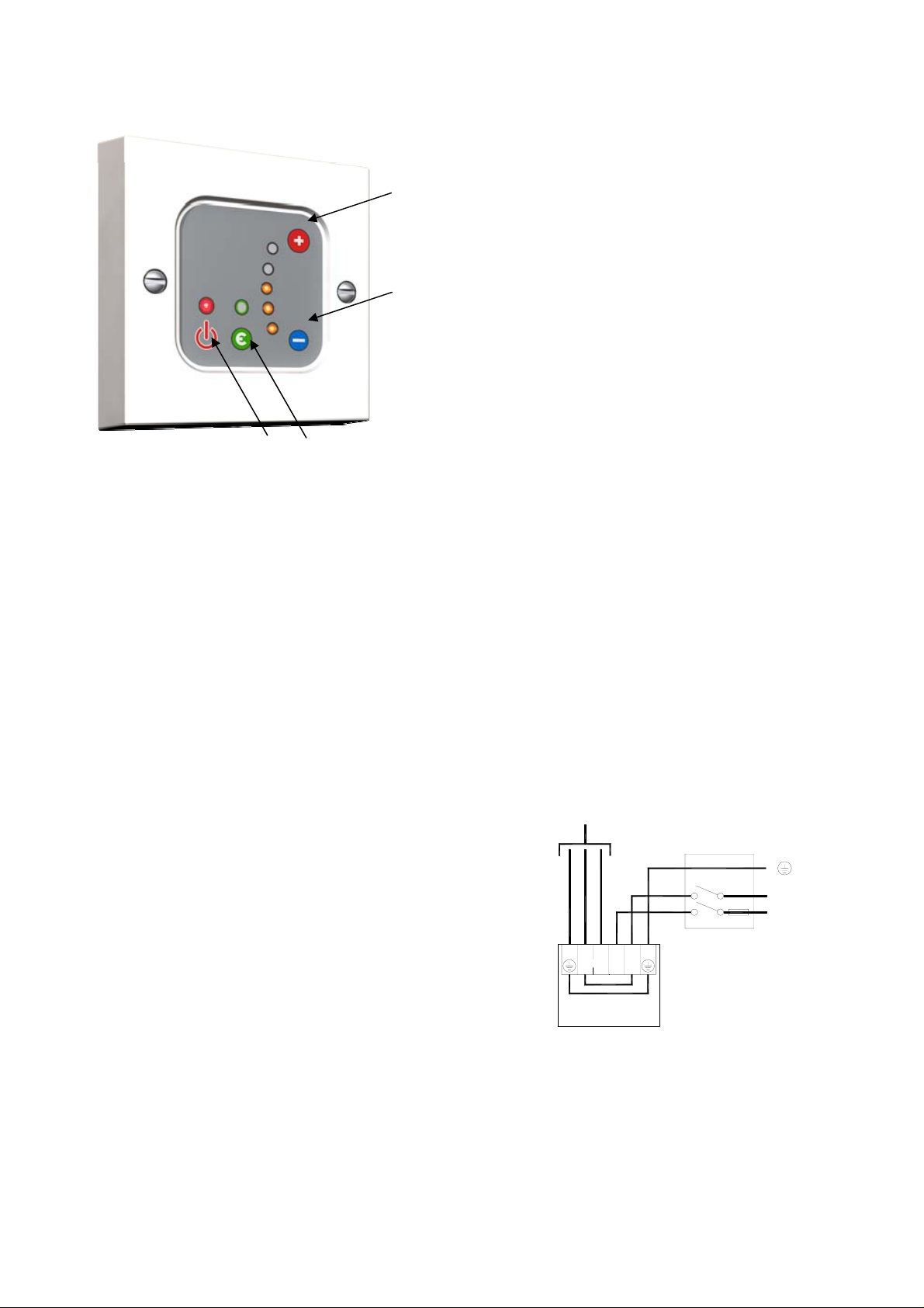
Electrical Element Wall
Controller Instructions
On/off
button
Eco boost
button
Electrical Element Wall
Controller
Please read the instructions thoroughly before
attempting to fit the product or attach it to your electrical
system.
If you are replacing the element please ensure that you
choose a suitably sized one for your towel rail. The
controller will only work with standard construction towel
rails and not PTC type elements.
Safety Precautions: This product should be fitted by a
competent person who can ensure compliance with IEE,
Part P and local authority regulations. Ensure the mains
electrical circuit and the fused spur unit are both isolated
before fitting. This controller should also be fitted within
the correct zone in the room.
Wiring the towel rail element
A fused spur is required in the supply circuit to the
controller, fitted with the correct size fuse. The 2 x E & 2
x N terminals are linked on the printed circuit board.
Electrical Element Wires
The element wires should be connected as follows;
Blue Neutral to one of the ‘N’ terminals
Brown Live to the ‘L’ LOAD terminal (NOT the terminal
marked ‘L’)
Green/Yellow Earth to one of the ‘E’ terminals
VERY IMPORTANT - This unit must be earthed
Mains Cable Wires
The mains wires should be connected as follows;
Blue Neutral to one of the ‘N’ terminals
Brown Live to the terminal marked ‘L’ (NOT ‘LOAD’)
Green/Yellow Earth to one of the ‘E’ terminals
VERY IMPORTANT - This unit must be earthed
Carefully fit the control plate into the back box ensuring
that no wires are trapped during the sitting process. Use
the two fixing screws to secure to the back box.
If using the side cable entry position, please ensure the
Cable clamp and screws are used.
447900A SUPPLIED BY APL 0911
Temperature
Increase
button
Temperature
Decrease
button
Operating instructions
There are four buttons on the control plate. The ‘on/off’
button, the temperature ‘increase/decrease’ buttons and
the ‘Eco’ boost button.
Basic operation
The unit in standby mode displays the main LED in
BLUE. To turn the unit on in normal mode, press the
‘on/off’ button and release it. The LED will turn RED, the
ORANGE LED bank will light between one to five LED’s.
To increase or decrease the temperature press the
‘increase/decrease’ buttons to attain the desired setting.
Each one of the ORANGE LED’s represents the
following power output from the element:
Power settings as below:
5 LEDs = 100% power
4 LEDs = 85% power
3 LEDs = 70% power
2 LEDs = 55% power
1 LED = 40% power
To turn the unit off, press the ‘on/off’ button and release
it. NB The control plate contains a memory and
whatever the temperature that was set when the unit
was turned off, will be the temperature (number of Led’s
lit) that the element will resume at when the unit is
turned on the next time.
ECO function
Press the ECO button from either power on or from
standard control, the power LED will turn GREEN. The
ECO function allows you to go to a higher power setting
for 30 minutes (To heat the towel warmer) this power
level can be set in the first 30 minutes. After 30 minutes
the power is reduced to the pre-set lower level for 90
minutes. The power output can be set using the
increase/ decrease buttons to set your preferred rail
temperature. After 2 Hours the controller will turn off.
Both the 30 minute and the 90 minutes settings are
saved in the controller.
FROM ELEMENT
1 Phase Supply
(220-240V 50Hz).
E
FUSE
N
~
L
E LNL NE
LOAD
LINKED ON PCB
LINKED ON PCB
CONTROLLER
Technical Data.
IP rating: IPX4
Voltage: 220-240 V AC
Maximum power output: 800w
Dimensions: 85 x 85 x 20mm
Approvals: CE,
tested to
EN55014-1:2006
 Loading...