

Page 1
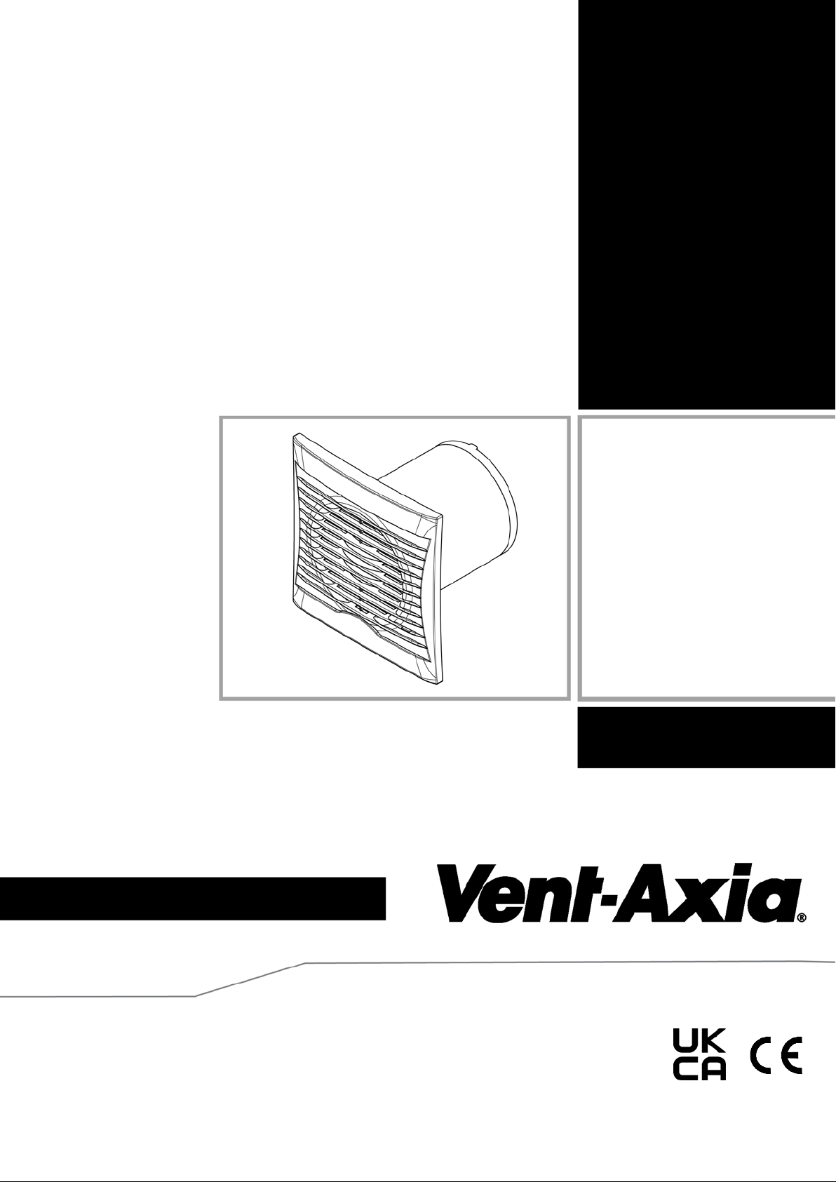
125mm AXIAL EXTRACT FAN
Installation and Wiring Instruct i ons
Stock Ref. N°
44 64 83
44 64 84
44 64 85
PLEASE READ INSTRUCTIONS IN CONJUNCTION WITH
ILLUSTRATIONS. PLEASE SAVE THESE INS
Silhouette
Lo
220-240V~50Hz
IPX4
-Carbon RANGE
TRUCTIONS.
- 125B
- 125T
- 125HT
Page 2

Installation and Wiring Instructions for t he Lo-Carbon Silhouette Ran ge of
Extractor Fans.
IMPORTANT:
READ THESE INSTRUCTIONS
BEFORE COMMENCING THE
INSTALLATION
DO NOT install this product in areas where the following may be present or occur:
• Excessive oil or a grease laden atmosphere.
• Corrosive or flammable gases, liquids or vapour s.
• Ambient temperatures higher than 40°C or less than –5°C.
• Possible obstructions which would hinder the access or removal of the Fan.
SAFETY AND GUIDANCE NOTES
A. All wiring to be in accordance with the current I.E.E.
Regulations, or the appropriate standards of your country
and MUST be installed by a suitably qualified person.
B. The Fan should be provided with a local isolator switch
capable of disconnecting all poles, having a contact
separation of at least 3mm.
C. Ensure that the mains supply (Voltage, Frequency, and
Phase) complies with the rating label.
D. The Fan should only be used in conjunction with the
appropriate Vent-Axia products.
E. The fan should only be used in conjunction with fixed wiring.
F. When the Fan is used to remove air from a room containing
a fuel-burning appliance, ensure that the air replacement is
adequate for both the fan and the fuel-burning appliance.
G. The Fan should not be used where it is liable to be subject
to direct water spray for prolonged periods of time.
H. Where ducted Fans are used to handle moisture-laden air, a
condensation trap should be fitted. Horizontal ducts shoul d
be arranged to slope slightly downwards away from the Fan.
I. This appliance is not intended for use by persons (including
children) with reduced physical, sensory or mental
capabilities, or lack of experience and knowledge, unless
they have been given supervision or instruction concerning
use of the appliance by a person responsible for their safety.
J. Children should be supervised to ensure that they do not
play with the appliance.
Page 3

K. Stationary appliances not fitted with means for disconnection
Stock Reference
Wall Kit
White
125
455226
from the supply mains having a contact separation in all
poles that provide full disconnection under over voltage
category III, the instructions state that means for
disconnection must be incorporated in the fixed wiring in
accordance with the wiring rules.
L. The exterior grille should be at least 2.3m above the ground
to prevent people from being able to access moving parts. If
the external grille is positioned between 0-2.3m from t he
ground, Please use the Vent-Axia wall kit as detailed below
to ensure people cannot access the fans impeller from the
outside.
DESCRIPTION
The Lo-Carbon Silhouette 125mm fan is an axial extraction fan suitable for domestic
bathrooms, W.C’s, kitchens and utility rooms. They are available as wall or panel
mounted models with shutter timer and humidity combinations.
Long life ball bearing DC motor with anti-vibration mounts provides low noise
transmission into plasterboard/panels.
High and low speed options available on all models to sui te the installation.
The fan can be wall or panel/ceiling mounted.
ACCESSORIES (not supplied)
WALL KIT
A 125mm wall kit is available for installing into most walls
using the liners supplied.
A. INSTALLATION
IMPORTANT: The fan should onl y be used in co nj un cti on wi t h fixed wi r ing.
PANEL/CEILING MOUNTING
1. For panel/ceiling mounting the fan should be installed into a closed duct system of
at least 1.2m long (max 3m) or protected by an exterior air grille that must comply
with the standard requir ements of your countr y to prevent access to th e fans
impeller.
2. Cut a130mm hole for 125mm fans.
3. Loosen the screw at the bottom of the grille and remove the front grille. Mark the
screw centres through t he holes in the fan back plate. Drill, plug and scre w into
position.
4. Attach ducting as required for the installation.
Page 4
5. Wire the fan as described in Section B-Wiring. Adjust any settings as required
(see Section C-Setup).
6. Replace the grille and tighten the retaining screw.
7. After installation, ensure impeller rotates freely and the shutters can open.
WALL MOUNTING
1. For wall mounting cut a 140 mm diameter hole for 12 5mm fans, through the wall
and insert the wall sleeve. Slope the sleeve slightly downwards away fr om the fan.
Cut to length and cement both ends into position flush with the wall faces.
2. Loosen the screw in the bottom of the grille and rem ove the front grille. Mark the
screw centres through t he holes in the fan back plate. Drill, plug and screw into
position. Fix exterior gr ille into position with the louvres positioned downwards.
(Note:- The grille must comply with the standard requirements of your country to
prevent access to the fans impeller. The wall kit u sed in this installation should
provide a minimum ducting lengt h of 100mm from the fans back plate to the inside
of the external grille).
3. Wire the fan as described in Section B-Wiring. Adjust any settings as required
(see Section C-Setup).
4. Replace the grille and tighten the retaining screw.
5. After installation, ensure impeller rotates f reely and the shutters can open.
B. WIRING.
WARNING: THE FAN AND ANCILLARY CONTROL EQUIPMENT MUST BE
ISOLATED FROM THE POWER SUPPLY DURING THE INSTALLATION /
OR MAINTENANCE.
IMPORTANT
• The fan should only be used in conjunction with fixed wiring.
• The cross - sectional area of supply cord used should be ranged from 1 -1.5mm2.
• Cable entry can only be made from the rear of the fan.
• The extraction fan is suitable for connection to 220-240V 50Hz supply.
• The fan is a class ll double insulated product and MUST NOT be earthed.
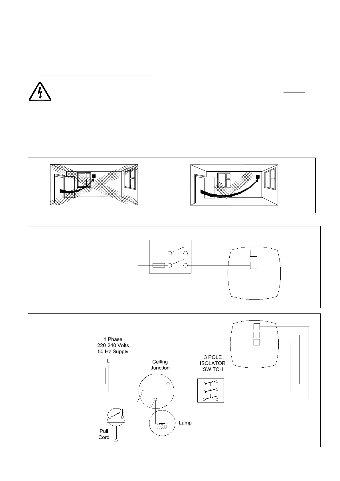
1. Select and follow the appropriate wiring diagram. ( Fig. 2 or 3)
2. Chec k all connections have b een made correctly and ensure all terminal
connections and cable cl amps are securely fastened.
3. Ensure the impeller rotates and is free from obstructions.
Page 5
C. SETUP
1
2
O
N
High speed (T/HT)
1
2
O
N
Low speed (T/HT)
WARNING: THE FAN AND ANCILLARY CONTROL EQUIPMENT MUST BE
ISOLATED FROM THE POWER SUPPLY DURING THE INSTALLATION /
OR MAINTENANCE.
ACCESSING THE CONTROL SETTIN GS – (Fig. 4)
1. Loosen the screw in the bottom of the grille and remove the front grille.
2. Carefully pull the inner cap from the centre of the fan away from the chassis.
3. Adjust the settings as outlined below.
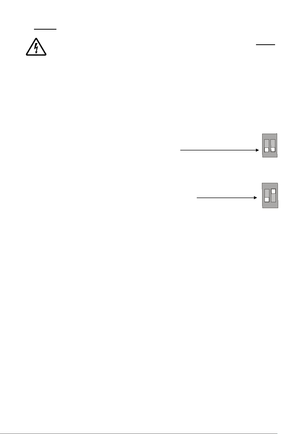
SPEED SETTING:
The fan has two speed settings for different installation requi rements:
1) High speed:
• T and HT models: Dip switch 2 in the ‘OFF’
position. (
• 125B models: Remove jumper (
Fig.5 – and right)
Fig.5)
2) Low speed (Factory set):
• T and HT models: Dip switch 2 should be in the
‘ON’ position. (
• 125B models: Replace jum per. (
Fig.5 – and right)
Fig.5)
Dip switch 1 should be in the ‘OFF’ posit ion (T and HT models only).
TIMER ADJUSTMENT (T AND HT MODELS)
BEFORE ADJUSTING THE TIMER, SWITCH OFF THE MAINS SUPPLY. TIMER
SHOULD ONLY BE ADJUSTED BEFORE OR DURING INSTALLATION.
1. Remove the fan grille. The controller is factory s et at 15 minutes approx.
The overrun time period can be adjusted from 1-30 minutes by altering the
adjuster on the control PCB.
2. To REDUCE the operating time, use a small screwdriver to turn the adjuster
Fig.5. CLOCKWISE.
3. To INCREASE the operating time, use a small screwdriver to turn the
adjuster Fig.5. ANTI-CLOCKWISE.
4. Replace the fan grille.
HUMIDITY SET-POINT ADJUSTMENT (HT MODELS ONLY)
BEFORE ADJUSTING THE CONTROLLER, SWITCH OFF THE MAINS SUPPLY.
HUMIDISTAT SHOULD ONLY BE ADJ USTED BEFORE OR DURING INSTAL LATION.
1. Remove the fan grille. The controller is factory s et to switch on at about
70% RH. The humidity set point can be adjusted from 65-95%RH by
altering the adjuster on the control PCB.
Page 6
2. To LOWER the set-point use a small screwdriver to turn the adjuster Fig.5.
Fig.3 Models: 125T, 125HT
~ N
N
L
S
L
Fan
FUSE
Fig.2 Models: 125B, 125HT (Timer not used)
~
N
L
1 PHASE SUPPLY
(220-240V 50Hz).
FUSE
SWITCHED
FUSED
SPUR
L
N
Fan
Fig.1.
ANTI-CLOCKWISE. This makes the controller MORE sensitive.
3. To RAISE the set-point use a small screwdriver to turn the adjuster Fig.5.
CLOCKWISE. This makes the controller LESS sensitive.
4. Replace the fan grille.
D. SERVICING AND MAINTENANCE.
WARNING: THE FAN AND ANCILLARY CONTROL EQUIPMENT MUST BE
ISOLATED FROM THE POWER SUPPLY DURING MAINTENANCE.
1. At intervals appropriate to the installation, the fan should be inspected an d cleaned to
ensure there is no build up of dirt or other deposits.
2. Wipe the inlets and front f ace with a damp cloth until clean.
The fan has sealed for li fe bearings, which do not require lubrication.
Page 7
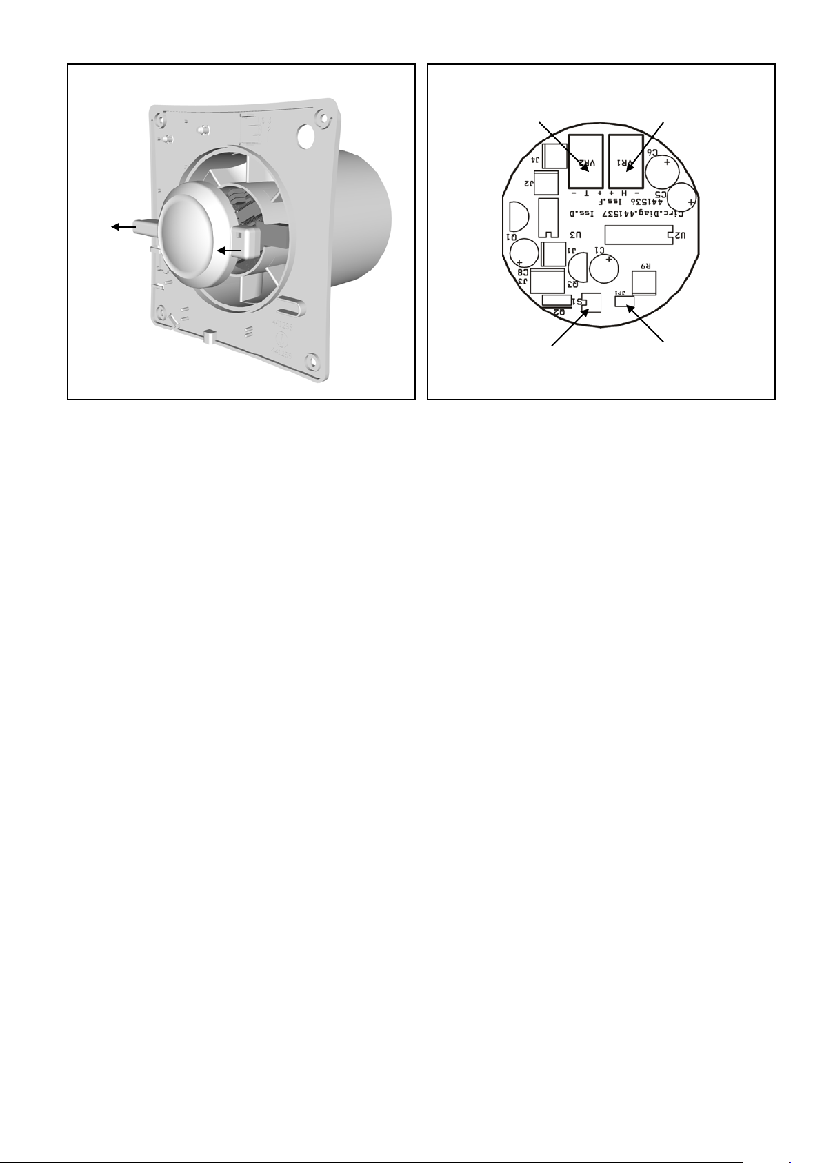
Fig.4. Accessing the control settings
Fig.5.
Timer
Humidistat
Speed adjustment
Jumper for
adjustment
adjustment
125B models
Page 8

446496B 0821
Head Office: Fleming Way, Crawley, West Sussex, RH10 9YX. Tel: 01293 526062 Fax: 01293 551188
EU Authorised Representative: Vent-Axia Bedrijv enweg 17 7442 CX Nijverdal Nederland. [email protected]
UK NATIONAL CALL CENTRE, Newton Road, Craw ley, West Sussex, RH10 9JA
SALES ENQUIRIES: Tel: 0344 8560590 Fax: 01293 565169
TECHNICAL SUPPORT: Tel: 0344 8560594 Fax: 01293 532814
For details of the warranty and returns procedure please refer to www.vent-axia.com or write to Vent-Axia Ltd, Fleming Way, Crawley, RH10 9YX
 Loading...