

Page 1
220
-
240V~50Hz
Lo-Carbon
PoziDry
Compact
Positive Pressure
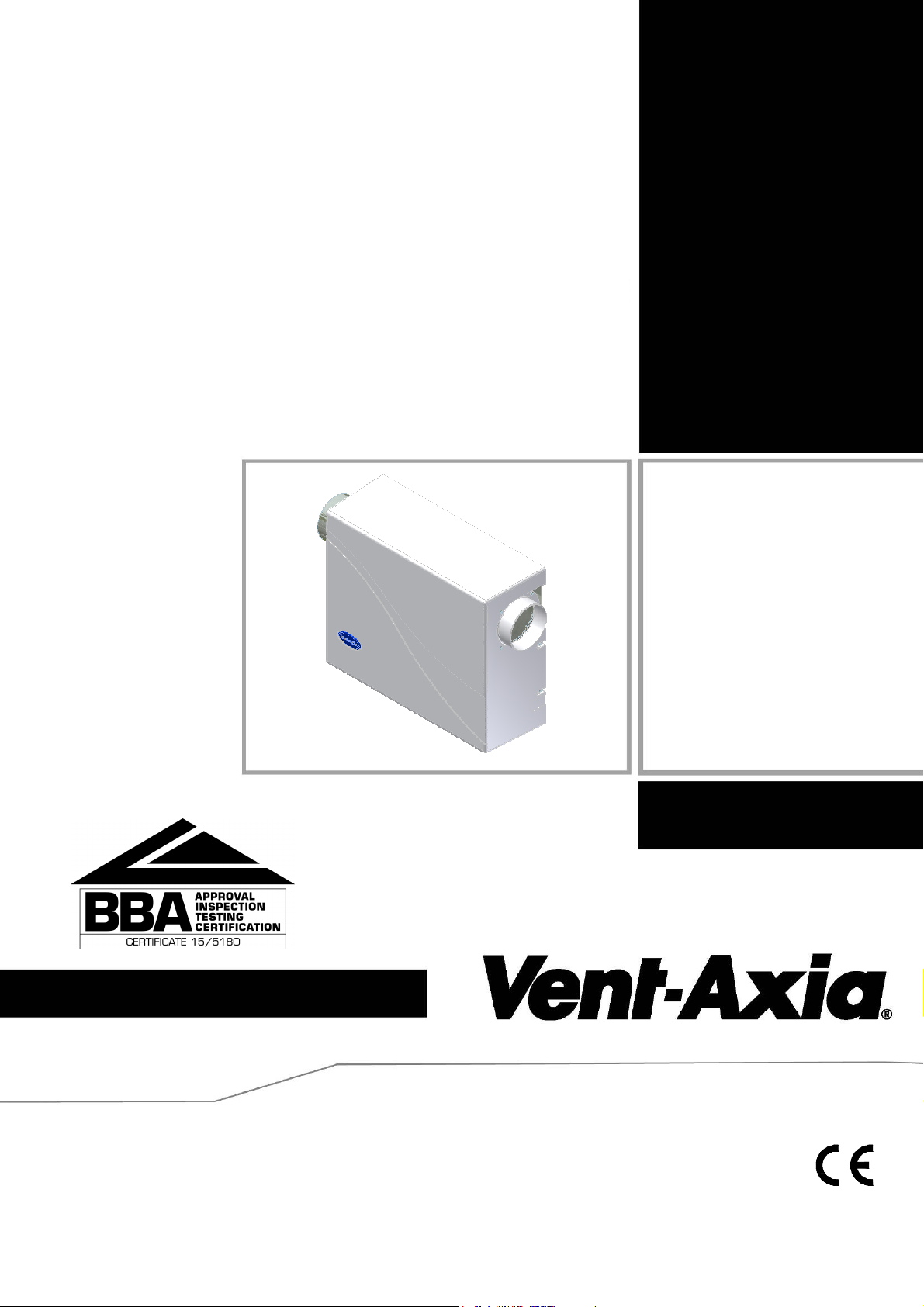
Ventilation Unit
Installation and Wiring Instructions
Stock Ref. N°
Pozidry Compact
444767 – With integral heater
444076 – Without heater
PLEASE READ INSTRUCTIONS IN CONJUNCTION WITH THE ILLUSTRATIONS.
PLEASE SAVE THESE INSTRUCTIONS
IP22
Page 2

Installation and Wiring Instructions for the
Lo-Carbon PoziDry Compact Positive Ventilation Unit.
IMPORTANT:
READ THESE INSTRUCTIONS BEFORE COMMENCING THE INSTALLATION
SAFETY AND GUIDANCE NOTES
1. DO NOT install this product in areas where the following may be present or occur:
1.1. Excessive oil or a grease laden atmosphere.
1.2. Corrosive or flammable gases, liquids or vapours.
1.3. Ambient temperatures higher than 40°C or less than -5°C.
1.4. Possible obstructions which would hinder access or removal of the Fan.
1.5 Relative humidity above 90%
1.6 Sudden ductwork bends or transformations close to the Unit.
2. All wiring to be in accordance with the current I.E.E. Regulations, or the appropriate standards of your country and
MUST be installed by a suitably qualified person.
3. The fan should be provided with a 3A fused, isolator switch capable of disconnecting all poles, having a contact
separation of at least 3mm.
4. Ensure that the mains supply (voltage, frequency, and phase) complies with the fan’s rating label.
5. The fan should not be used where it is liable to be subjected to direct water spray.
6. This appliance is not intended for use by persons (including children) with reduced physical, sensory or mental
capabilities, or lack of experience and knowledge, unless they have been given supervision or instruction concerning
use of the appliance by a person responsible for their safety.
7. Children should be supervised to ensure that they do not play with the appliance.
A. INTRODUCTORY NOTES
The Vent-Axia Lo-CARBON POZIDRY COMPACT is a positive input ventilation unit, designed to be installed in
apartments taking fresh air from outside and supplying the air, filtered, into the building.
The Lo-Carbon PoziDry Compact has two fully adjustable speed settings; ‘Trickle’ and ‘Normal’. These speeds are
set on installation, but to aid commissioning there are pre-marked settings to suit the characteristics of the house
The unit uses a sensor to monitor the incoming air temperature, automatically adjusting the air volume when
necessary.
‘Trickle’ speed is automatically selected when the ambient incoming temperature is less than 18°C.
‘Normal’ is automatically selected when the ambient incoming temperature is between 18°C and 27°C.
If the ambient incoming air temperature exceeds 27°C, the unit will automatically switch to standby (no airflow, LED
displaying one segment). The standby power consumption is 2W.
In the case of the integral heater version, the heater element is automatically activated when necessary and tempers
the supply air to between 10°C and 20°. This temperature can be set using the adjuster located between the Trickle
and Normal speed adjusters.
By wiring in a switch on installation it is possible to switch off the heater if its use is not necessary. See wiring
section.
The Vent Axia Lo-Carbon PoziDry has the capability to run on Purge setting (maximum speed); this is particularly
useful for installations where condensation has been a severe problem in order to help dry the property out. Mould
will turn to a dry grey powder when dried out and should be vacuumed up.
To enable ‘Purge’ speed, connect a switched live connection to the LS core on the integral mains flying lead. See
WIRING on pages 5 and 6 and the notes on page 7.
The unit also incorporates a non-resettable elapsed hours counter.
2
Page 3
B. INSTALLATION
The Lo-CARBON POZIDRY COMPACT can be wall-mounted using the bracket and fixings supplied. A paper
template is also supplied.
The wall should have sufficient strength to support the unit.
Take into consideration the routing of the cable and the ducting that must be fitted to both the inlet and discharge
spigots.
The unit must always be mounted on a vertical wall with the spigots nearest the top of the unit, with a horizontal
airflow.
PLEASE LOCATE THE SEPARATELY BAGGED FILTER!
Wall-mounting
Take off the white plastic cover by removing the 4 screws at the sides.
Take off the metal front cover by removing the 4 screws.
Carefully remove the round to rectangular duct adaptor, packed loosely in the filter plenum (internal, near to the
white plastic spigot). The filter is bagged separately to the unit.
Handing
The Lo-CARBON POZIDRY COMPACT is supplied with the airflow direction horizontally from right to left. If the
opposing airflow is required (left to right), the following should be carried out:
Re-position the cable gland by first loosening off the gland to allow the cable to be pulled through back into the unit.
Swap the cable gland and the blanking plug over to each others’ positions.
Re-secure the cable through the cable gland.
Take off the rear metal cover by removing the 4 screws, and re-fix to the other side of the unit in place of the metal
front cover.
Carefully cut out the skinned area on the white plastic cover where the cable gland will now lie.
Rear-entry inlet
If rear-entry inlet duct connection is required, the appropriate blanking plate (closest to the white plastic inlet spigot),
should be changed over with the white plastic inlet spigot/seal.
The paper template supplied indicates rear entry spigot centres in relation to the fixing hole centres.
Either handing:-
Use the paper template to mark the required fixing-hole positions for the bracket and unit on the wall.
Drill the wall and fit suitable wall plugs to all four positions.
Using 2 suitable size screws fit the mounting bracket to the wall.
Offer the unit up to the wall and allow the mating part on the unit to sit inside the mounting bracket, and then secure
the unit to the wall with suitable size screws through the 2 key-way holes on the back-plate of the unit.
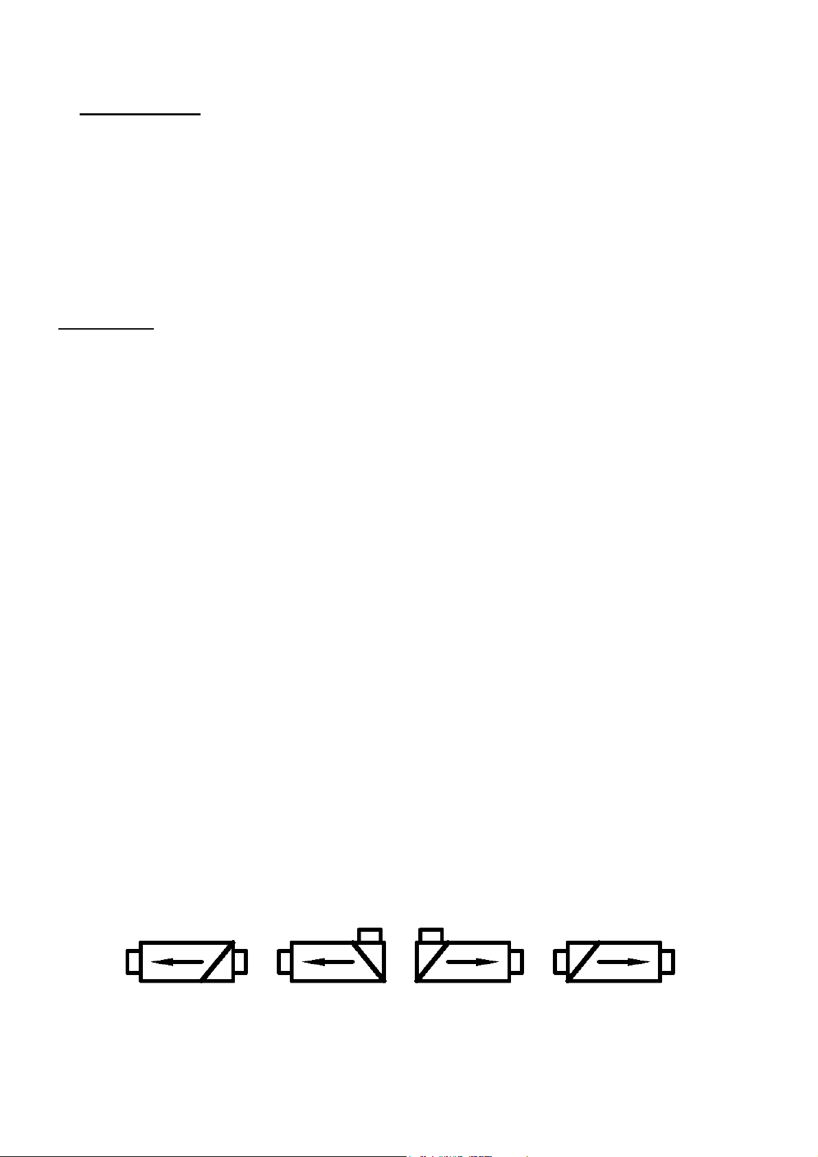
Fit the separately bagged filter using the diagram below to ensure that it is fitted to suit the relevant handing/inlet
spigot position. There are guides in the filter plenum to allow fitting of the filter in two directions. The diagram below
shows the four possible airflow/inlet spigot arrangement options. The arrow shows the airflow direction. The diagonal
line behind the tail of the arrow shows which direction to slide the filter in.
VIEW FROM THE TOP OF THE UNIT
Re-fix the metal front cover.
Following commissioning, re-fix the white plastic cover.
3
Page 4
C. WIRING
WARNING: THE POSITIVE VENTILATION UNIT AND ANY ANCILLARY CONTROL EQUIPMENT
MUST BE ISOLATED FROM THE POWER SUPPLY DURING THE INSTALLATION OR
MAINTENANCE.
THE Lo-Carbon PoziDry Compact (POSITIVE VENTILATION UNIT) MUST BE EARTHED.
Mains supply voltages (220-240V ac) are present in this equipment which may cause death or serious injury by
electric shock. Only a qualified electrician or installer should connect the power supply to this unit.
The Lo-Carbon PoziDry is designed for operation from a single-phase alternating current source (220-240V AC).
An integral mains flying lead is connected to the unit for connection to a 3A switched fused spur. It should be
capable of disconnecting all poles, having a contact separation of at least 3mm.
If a heater switch is required in order to turn the heating element on and off during Trickle ventilation operation, a
single pole, one-way switch can be wired in to the Lo-Carbon PoziDry heater version terminal block by removing the
link between H & L and replacing with the heater switch wires; thus making and breaking the live supply to the
heater. There is a 16mm hole provided with a plug stopper fitted in the front panel of the Lo-Carbon PoziDry. This
should be removed and replaced with a suitable cable gland. The heater switch cable can be fed through the cable
gland and into the terminal strip. The heater switch cable should be located under the cut-out in the terminal cover
together with the fan and thermistor cables when the terminal cover is replaced. The switch, cable and cable gland
which are not supplied should be rated at 3 amps.
TO CONNECT A POWER SUPPLY:
• Ensure the local AC power supply is isolated.
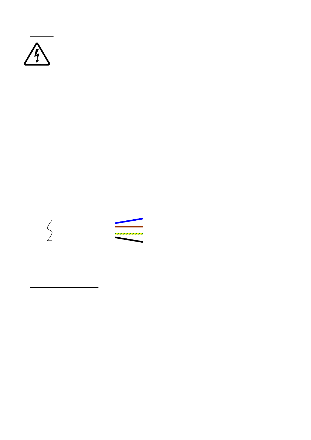
• The product has a pre-wired flying lead. Connect the brown core to Live, blue core to Neutral, green/yellow to
Earth, and black to LS (for 100% PURGE if required).
• Use cable clamps and clips to secure the cable, as appropriate.
• Maximum heater power 300W and motor power 15W
Blue – Neutral
Brown – Live
Green/yellow – Earth
Black – Switched Live (LS)
D. START UP SEQUENCE
The Lo-Carbon Pozidry Compact will perform a start up test procedure on every power up.
During this sequence, the following will occur:
1) Motor goes to full speed.
2) LED segments light up one at a time until all 7 are lit.
3) Potentiometers and Thermistor are measured and the motor pulses counted. If any of these sources shows an
error, then it is displayed. A list of error codes is shown below.
4) Motor goes to lowest (Normal) speed; if the motor stalls then an ‘error’ is displayed. Otherwise the display shows
'n' indicating Normal speed.
5) After 10 seconds the heater is turned on, the display now shows 'h.' for heat.
6) After 20 seconds (to allow the element to warm up) the heater is turned off, the motor goes to maximum Normal
speed to cool the heater and the display shows 'b' indicating Normal speed.
7) After 10 seconds the display shows the elapsed hours. Six digits are displayed sequentially immediately
after the ‘b’. For example, 000048 would indicate 2 complete days has elapsed.
8) The unit exits the test mode and runs at the appropriate rate whilst displaying a rotating segment display. The rate
will depend upon ambient temperature.
4
Page 5
The Lo-Carbon PoziDry Compact has built in fault detection software to ensure continual safe functioning.
If any of these faults are displayed on the LCD display please contact Technical Support on 0844 8560594.
F1 = open circuit thermistor i.e. not connected.
F2 = short circuit thermistor i.e. wires, PCB or thermistor shorted.
The above codes are mutually exclusive so cannot occur at the same time.
F3 = Motor Tachometer signal failure or fan not rotating.
F4 = Motor AND open circuit thermistor failures.
F5 = Motor AND short circuit thermistor failures.
CAUTION:
As the heater element is activated during this sequence, the ducting must be attached.
Please take extreme caution after the self test as the unit may become hot.
E. COMMISSIONING
The Lo-Carbon PoziDry Compact has two speed settings, ‘Trickle’ and ‘Normal’.
‘Trickle’ speed is automatically selected when the ambient incoming temperature is below 18°C.
‘Normal’ is automatically selected when the ambient incoming temperature is between 18°C and 27°C.
If the ambient incoming air temperature exceeds 27°C, the Lo-Carbon PoziDry Compact automatically switches to
standby (no airflow).
The speed settings on the Lo-Carbon PoziDry Compact are fully adjustable via the potentiometers located on the
front of the unit.
As marked on the unit, the left hand potentiometer controls the ‘Trickle’ speed setting.
The right hand potentiometer controls the ‘Normal’ speed setting.
The central potentiometer (if available) controls the heat setting for integral heater version (444767).
WARNING: THE BLUE POTENTIOMETER DRIVER SUPPLIED WITH THE UNIT MUST BE USED
TO ADJUST THE POTENTIOMETERS.
Turning the potentiometers clockwise will increase the speed/temperature value.
Once speed/temperature is set, apply the clear label over the marked area containing the potentiometers to ensure
the potentiometers are inaccessible and so that the unit returns to an IP X2 rated status.
The fan speeds must be selected to suit the condensation level of the house.
The condensation level of a house is affected by a combination of factors and not just house size, but research by
the Building Research Establishment and other bodies has shown that a ventilation rate equal to half the volume of
the house per hour will provide adequate background ventilation, therefore for ease of installation the Lo-Carbon
Pozidry Compact can be commissioned based on house size.
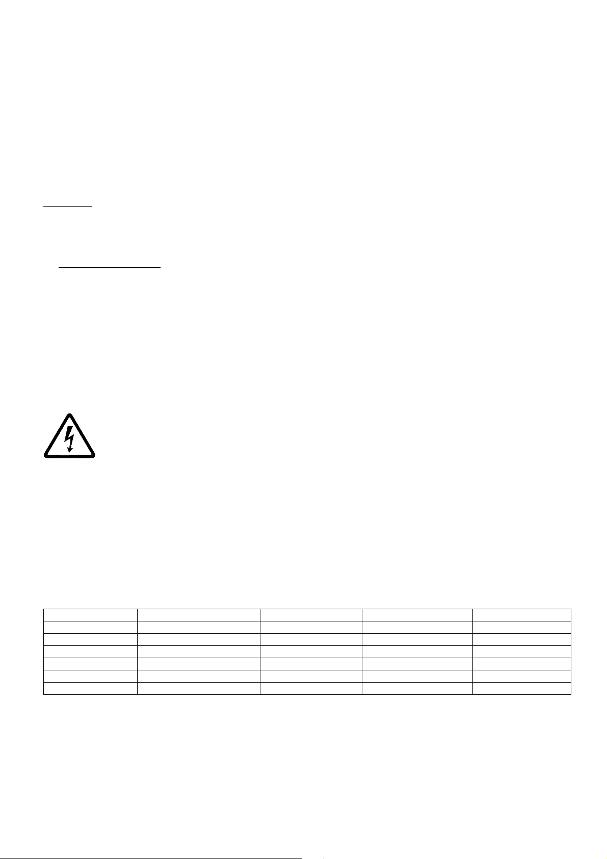
Based on this air change rate the following speeds are recommended:
Setting Airflow, l/s (m3/h) Floor area, m2 Power, W SFP, W/l/s
1 13 (47) 39 4.6 0.35
2 16 (57) 48 5.3 0.33
3 21 (74) 62 7.4 0.35
4 24 (85) 71 9.1 0.38
5 27 (96) 80 11.8 0.44
6 29 (104) (boost only) 13.6 0.47
This performance is achieved with the optional installation pack 453546 as described below, with two quick fit grilles.
As a guideline the ‘Normal’ speed setting should be the ‘Trickle’ speed setting plus two, however as houses vary in
size, this is not always the case, in some houses the ‘Normal’ speed may need to be less than this guideline speed.
Note: Figures based on a 2.4 m ceiling height.
The factory setting is ‘Trickle’ Setting 1 and ‘Normal’ setting 3.
5
Page 6
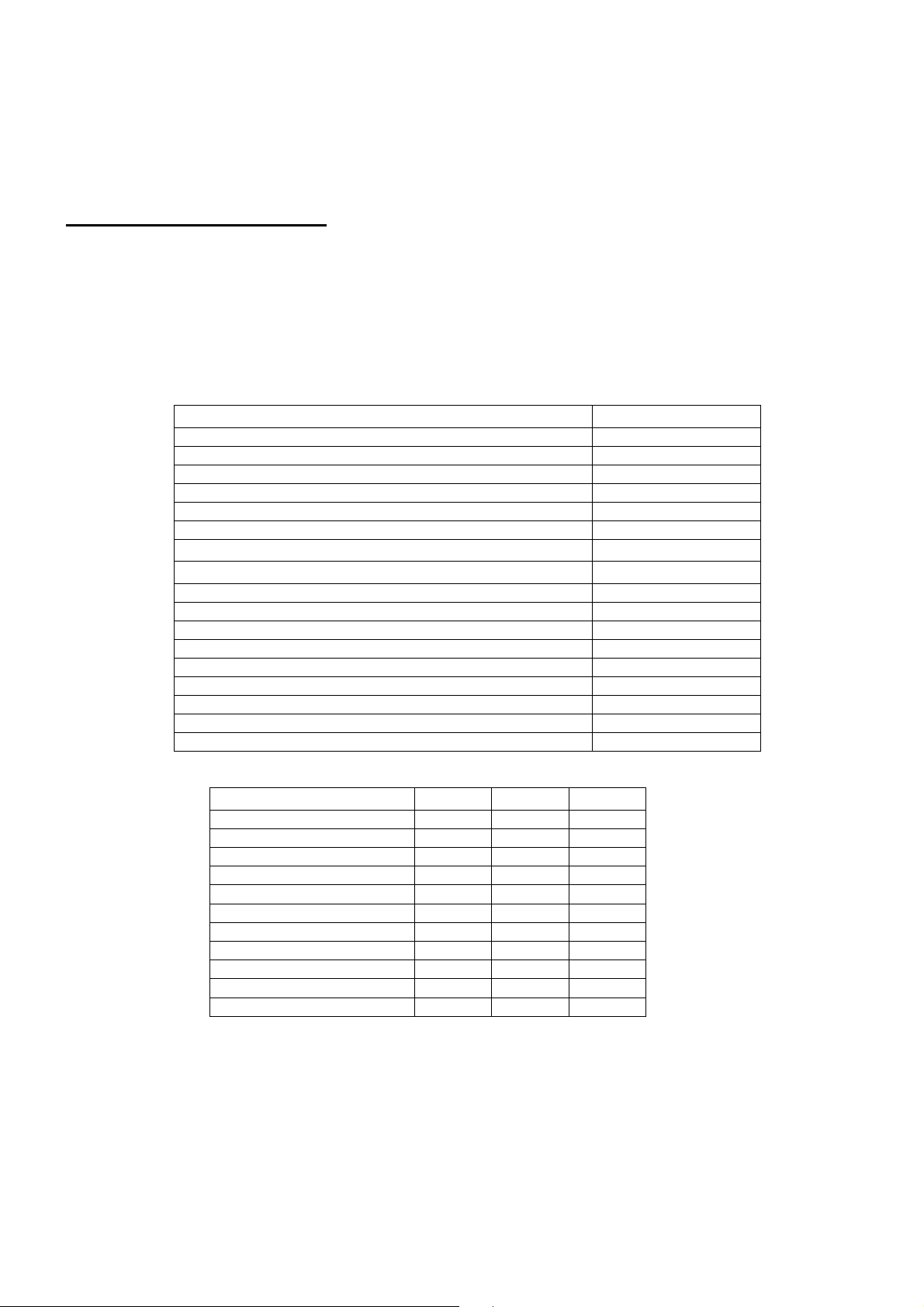
In many installations where condensation is a severe problem; it is recommended to run the fan at purge
Spares
Accessories
Installation Packs
Stock Reference
: - 453546
453547
453548
speed for a couple of weeks to ventilate the house thoroughly. This can be achieved by utilizing the LS
input option, whereby the unit will run on Purge setting until the LS signal is terminated. To achieve this,
connect the LS core of the integral mains flying lead to an LS input.
It is the responsibility of the installer to ensure that appropriate speeds are selected.
F. SERVICING AND MAINTENANCE
The fan motor uses sealed ball bearings, and does not require further lubrication.
Apart from filter change the Lo-Carbon Pozidry Compact contains no user serviceable parts.
Under normal conditions; i.e. away from main roads and industrial areas it is recommended that the filter is checked
annually and cleaned or replaced as necessary. Otherwise change as required.
The filter may be gently cleaned with a vacuum cleaner or washed in a soapy water solution and allowed to air dry
before re-fitting. Do not dry the filter in a tumble dryer.
Spare filters are available from Vent-Axia Sales Centres.
Stock Reference
Filter 447381
Front cover 447383
Control PCB 447385
PSU PCB 447386
Motor/impeller 447384
Heating element (integral heater version 444767 only) 447391
Elbow - 90 degree bend, (100 dia.) 400752
Duct - 2.0 m length, (100 dia.) 5108250
Wall fitting kit - white 254102
Wall fitting kit - brown 254100
Quick Fit 100mm wall grille - white 563521
Quick Fit 100mm wall grille - brown 563541
Quick Fit 100mm termination 563535A
Air replacement set (door grille) - ivory 561401
Air replacement set (door grille) - brown 561400
Quick-fit grill, white 1 1 1
Wall fitting kit, brown 1 1 1
HR 70WH Rnd-Rect Ad 1 3 3
HR 060WH Vert 90° bend
Ind 040WH Elbow/Spgt 1 1 1
HR 010WH 1m Flat Chnl 1 2 2
HR 015WH 1.5m Flat Chnl 1 2 2
HR 020WH Connector 1 4 4
HR 050WH Horiz 90° bend
HR 122-H Chnl Clip 4 6 2
2 2 2
- - 2
6
Page 7

G. FAULT FINDING.
Local Demand
Local Dema
nd
carry over (for regenerative heat exchangers only),
The Lo-Carbon PoziDry has built in fault detection software to ensure continual safe functioning.
If one of the following faults appears on the LCD display please contact Technical Support on 0844 8560594.
F1 = Open circuit thermistor i.e. not connected.
F2 = Short circuit thermistor i.e. wires, PCB or thermistor shorted.
The above codes are mutually exclusive so cannot occur at the same time.
F3 = Motor Tachometer signal failure or fan not rotating.
F4 = Motor AND open circuit thermistor failures.
F5 = Motor AND short circuit thermistor failures.
PRODUCT FICHE
For Residential Ventilation Units (Complying Commission Delegated Regulation (EU) No 1254/2014)
Name: Vent-Axia Vent-Axia
Model ID (Stock Ref.) :
SEC Class E E
SEC Value ('Average') 28.30 28.30
SEC Value ('Warm') 12.80 12.80
SEC Value ('Cold') 55.36 55.36
Label Required? (Yes/No=Out of scope) Yes Yes
Declared as: RVU or NRVU/UVU or BVU RVU-UVU RVU-UVU
Speed Drive Multi-Speed Multi-Speed
Type HRS (Recuperative, Regenerative, None) None None
Thermal Eff: [ (%), NA(if none)] N/A N/A
Max. Flow Rate (m3/h) 122.40 122.40
Max. Power Input (W): (@Max.Flow Rate) 49.80 49.80
LWA: Sound Power Level (dB) N/A - (Ducted) N/A - (Ducted)
Ref. Flow Rate (m3/s) 0.02 0.02
Ref. Pressure Diff. (Pa) TBC TBC
SPI [W/(m3/h)] 0.58 0.58
Control Factor & Control Typology: (CTRL/ Typology)
Control Factor; CTRL 0.65 0.65
Control Typology
Declared: -Max Internal & External Leakage Rates(%) for BVUs or
-&Ext. Leakage Rates (%) for Ducted UVUs;
Mixing Rate of Non-Ducted BVUs not intended to be equipped
with one duct connection on either supply or extract air side;
Filter Warning (RVU) No No
For UVUs (Instructions Install Regulated Supply/Extract Grilles
Façade)
Internet Address (for Disassembly Instructions) www.vent-axia.com www.vent-axia.com
Sensitivity p. Variation@+20/-20 Pa: (for Non-Ducted Vus) TBC TBC
Air Tightness-ID/OD-(m3/h) (for Non-Ducted Vus) TBC TBC
Annual Electricity Consumption: AEC (kWh/a) 9.54 9.54
Annual Heating Saved: AHS (kWh/a)
AHS: Average 28.30 28.30
AHS: Warm 12.80 12.80
AHS: Cold 55.36 55.36
Lo-Carbon PoziDry
Compact - 444076
Control
TBC TBC
N/A N/A
In F&W In F&W
Lo-Carbon PoziDry
Compact - 444767
Control
7
Page 8
Applicable only to products installed and used in the United Kingdom. For details of guarantee outside the United Kingdom contact your local
Vent-Axia guarantees its products for two years from date of purchase against faulty material or workmanship. In the event of any part being
found to be defective, the product will be repaired, or at the Company’s option replaced, without charge, provided that the product:-
• Has been installed and used in accordance with the instructions given with each unit.
• Has not been connected to an unsuitable electricity supply. (The correct electricity supply voltage is shown on the product rating
label attached to the unit).
• Has not been subjected to misuse, neglect or damage.
• Has not been modified or repaired by any person not authorised by the company.
Please return the complete product, carriage paid to your original supplier or nearest Vent-Axia Centre, by post or personal visit. Please ensure
that it is adequately packed and accom panied by a letter clearly marked “Guarantee Claim” stating the nature of the fault and providing
The
Guarantee
supplier.
IF CLAIMING UNDER TERMS OF GUARANTEE
evidence of date and source of purchase.
Head Office: Fleming Way, Crawley, West Sussex, RH10 9YX. Tel: 01293 526062 Fax: 01293 551188
UK NATIONAL CALL CENTRE, Newton Road, Crawley, West Sussex, RH10 9JA
SALES ENQUIRIES: Tel: 0844 8560590 Fax: 01293 565169
TECHNICAL SUPPORT: Tel: 0844 8560594 Fax: 01293 539209
For details of the warranty and returns procedure please refer to www.vent-axia.com or write to Vent-Axia Ltd, Fleming Way, Crawley, RH10 9YX
447360 D 0516
8
 Loading...