

Page 1
Sentinel
Kinetic MVHR Range
Installation & Commissioning
Stock Ref. N°
438222 Kinetic B Right
438222L Kinetic B Left
443319 Kinetic BH Right
443319L Kinetic BH Left
408167 Kinetic FH Right
408169 Kinetic FH Left
443028 Kinetic Plus B Right
443028L Kinetic Plus B Left
408449 Kinetic High Flow Right
408451 Kinetic High Flow Left
PLEASE RETAIN THESE INSTRUCTIONS WITH THE PRODUCT.
Copyright © 2009 Vent-Axia Limited. All rights reserved.
Page 2

Warnings & Safety Information
IMPORTANT SAFETY INFORMATION
PLEASE READ THESE
INSTRUCTIONS CAREFULLY
BEFORE COMMENCING
INSTALLATION.
1. Do not install this product in areas where
the following may be present or occur:
• Excessive oil or a grease laden
atmosphere.
• Corrosive or flammable gases, liquids or
vapours.
• Subject to direct water spray from hoses.
• Ambient temperatures higher than 40°C
and lower than -20°C.
• Possible obstructions that may hinder
access to or removal of the unit.
2. All wiring must be in accordance with the
current IEE wiring regulations BS7671, or
appropriate standards of your country.
Installation should be inspected and tested
by a suitably qualified person after
completion.
3. Ensure the mains supply (voltage,
frequency and phase) complies with the
rating label.
4. The unit should be provided with a local
double pole fused spur fitted with a 3A fuse
having a contact separation of at least 3mm.
5. These units must be earthed.
6. Precautions must be taken to avoid the
back-flow of gases into the building from the
open flue of gas or other fuel-burning
appliances.
7. This appliance is not intended for use by
persons (including children) with reduced
physical, sensory or mental capabilities, or
lack of experience and knowledge, unless
they have been given supervision or
instruction concerning use of the appliance
by a person responsible for their safety.
8. Young children should be supervised to
ensure that they do not play with the
appliance.
INSTALLATION GUIDANCE
1. The installer is responsible for the installation and
electrical connection of the sentinel system on site. It is the
responsibility of the installer to ensure that the equipment is
safely and securely installed and left only when
mechanically and electrically safe.
2. All regulations and requirements must be strictly
followed to prevent hazards to life and property, both
during and after installation, and during any subsequent
servicing and maintenance.
3. The unit’s condensate drain must be connected to the
building’s wastewater drainage system.
4. Certain applications may require the installation of sound
attenuation to achieve the sound levels required.
5. The unit must not be connected directly to a tumble
drier.
6. The supply and exhaust valves must be fully opened
prior to commissioning.
7. The supply air must be drawn from the exterior of the
property.
8. The unit should be allowed to stabilise during
commissioning for a minimum period of 5 minutes when
changing between boost and normal speeds.
9. Ensure that the unit’s external grilles are a minimum of
1500mm apart. The exhaust grille should be located at
least 600mm away from any flue outlet. The inlet grille
should be located 2000mm away from any flue outlet.
10. This product and associated duct installation should be
carried out in accordance with the domestic ventilation
compliance guide.
Disposal
This product should not be disposed of with
household waste. Please recycle where
facilities exist. Check with your local authority
for recycling advice.
Sentinel Kinetic MVHR Installation & Commissioning 2
Page 3

About this Document
ContentsIMPORTANT SAFETY INFORMATION .................. 2
INSTALLATION GUIDANCE ........................................................... 2
Product Description 4
Sentinel Kinetic, Sentinel Kinetic F, Sentinel Kinetic Plus & Sentinel
Kinetic High Flow ............................................................................. 4
Technical Data 6
Sentinel Kinetic Performance graph for Horizontal Discharge ....... 9
Sentinel Kinetic F Performance graph for Vertical and Horizontal
Discharge ....................................................................................... 10
Sentinel Kinetic Plus Performance graph for Vertical and Horizontal
Discharge ....................................................................................... 11
Sentinel Kinetic High Flow Performance graph for Vertical and
Horizontal Discharge...................................................................... 11
Installation ...................................................................................... 11
Before Installation of the Unit ........................................................ 12
Unit Installation............................................................................... 12
Electrical Installation ...................................................................... 20
Powering Up the Unit ..................................................................... 23
Control Unit Display ....................................................................... 23
Start-up Screens ............................................................................ 24
Commissioning 28
Overview ........................................................................................ 28
Control Unit Screens Summary ..................................................... 29
Commissioning Screens ................................................................ 30
UK Building Regulations (Part F)
Declaration of Conformance
The Sentinel Kinetic conforms to the 2010 Building
Regulations (Part F - Means of Ventilation requirements) for
installed performance of a ducted mechanical extract fan
when installed in accordance with the instructions in this
document.
Note:
Read in conjunction with the User Instruction Manual
442073
Maintenance 40
Filter Maintenance ......................................................................... 40
Periodic Maintenance .................................................................... 40
Spares ............................................................................................ 41
Troubleshooting 42
Diagnosing a Problem ................................................................... 42
Appendix One: Control Mode 02 Description 44
Overview ........................................................................................ 44
Terminal Connections and Functions............................................ 44
Airflow Mode Selection .................................................................. 45
Appendix Two: Options and Accessories 46
CO2 Sensor.................................................................................... 46
Normal / Boost Switch ................................................................... 46
Humidistats..................................................................................... 46
Connecting a System Cooker Hood .............................................. 46
Connecting an Opto-coupler (447340) .......................................... 46
Wired Remote Control (443283) ................................................... 47
Isolator Relay Controller (442030) ................................................ 47
Remote LED Inducator .................................................................. 48
Sentinel Kinetic MVHR Installation & Commissioning 3
Page 4
Product Description
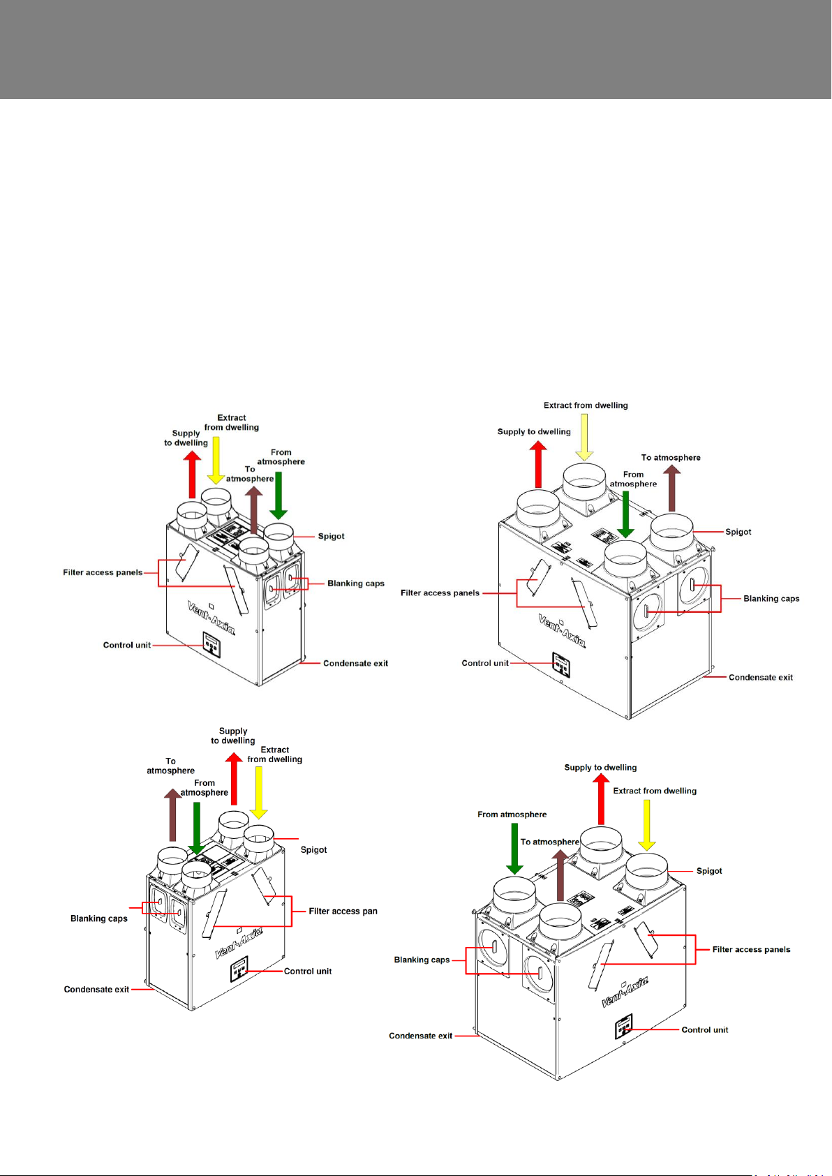
Fig 4: Sentinel Kinetic F, Sentinel Kinetic Plus and High Flow
Left handed
Fig 3: Sentinel Kinetic Left handed
Fig 2: Sentinel Kinetic F, Sentinel Kinetic Plus and High Flow
Right handed
Fig 1: Sentinel Kinetic Right handed
Product Description
Sentinel Kinetic, Sentinel Kinetic F, Sentinel Kinetic Plus & Sentinel Kinetic High Flow
The Vent-Axia Sentinel Kinetic, Sentinel Kinetic F, Sentinel Kinetic Plus & Sentinel Kinetic High Flow
Mechanical Ventilation/Heat Recovery (MVHR) are heat recovery units designed for the energy efficient
ventilation of houses and similar dwellings, conforming to the latest requirements of the Building Regulations
document F 2010.
The units are designed for continuous 24 hour exhaust ventilation of stale moist air from bathrooms, toilets and
kitchens. As the stale air is extracted, a heat exchanger within the unit transfers up to 90% of the heat into the
supply air entering the bedrooms and lounge.
Units are available with the condensate drain on the right or left hand side.
Sentinel Kinetic MVHR Installation & Commissioning 4
Page 5

Product Description
Models
438222 - Sentinel Kinetic B Right, right handed with summer bypass.
438222L - Sentinel Kinetic B Left, left handed with summer bypass.
443319 - Sentinel Kinetic BH Right, right handed with summer bypass and integral humidity sensor.
443319L - Sentinel Kinetic BH Left, left handed with summer bypass and integral humidity sensor.
408167 - Sentinel Kinetic FH Right, right handed with summer bypass and integral humidity sensor.
408169 - Sentinel Kinetic FH Left, left handed with summer bypass and integral humidity sensor.
443028 - Sentinel Kinetic Plus B Right, right handed with summer bypass and integral humidity sensor.
447938 - Sentinel Kinetic Plus B Left, left handed with summer bypass and integral humidity sensor.
408449 - Sentinel Kinetic High Flow Right, right handed with summer bypass and integral humidity sensor.
408451 - Sentinel Kinetic High Flow Left, left handed with summer bypass and integral humidity sensor.
Accessories
441838 - Sentinel Kinetic Plug-in integral humidity sensor
442367 - Monza System Cooker Hood 600mm wide
442368 - Latina System Cooker Hood 900mm wide
443283 - Wired Remote Control.
447340 - Opto-Coupler
409761 - Spigot Adaptor Kit 200mm – (High Flow)
448356 - LED
A range of sensors can be used to manage system demand and control the ventilation rate. These include an internal
humidity sensor, humidity sensors for independent mounting in rooms, CO2 sensor, Vent-Wise sensors, manual
switches and pull cords. For these alternative control options, see www.vent-axia.com
Sentinel Kinetic MVHR Installation & Commissioning 5
Page 6
Installation
Performance
Sentinel Kinetic
Sentinel Kinetic F
Sentinel Kinetic Plus
Sentinel Kinetic High Flow
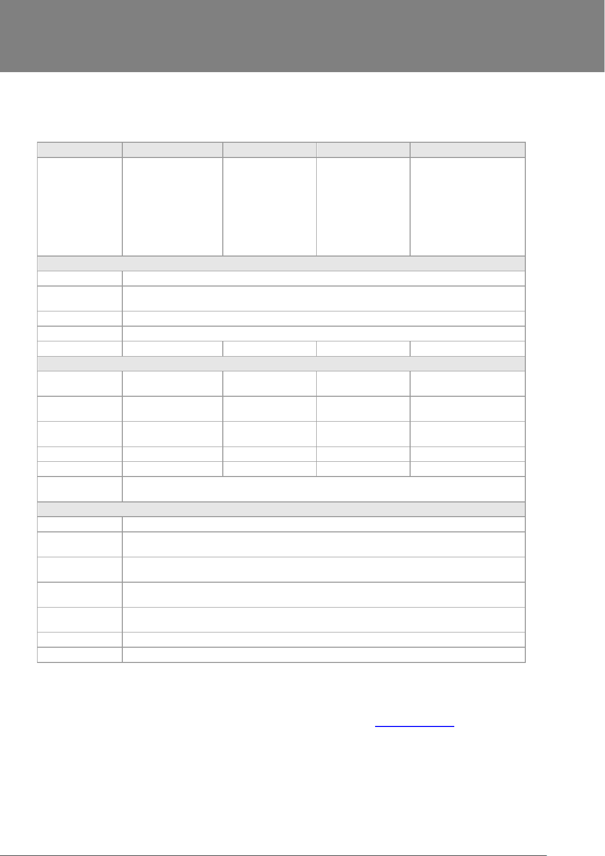
Airflow
Maximum, FID,
290 m3/h
Low defaultt 20%
Normal default 30%
Boost default 50%
Purge 100%
(For commissioning
graphs see page 10)
Maximum, FID,
335 m3/h
Low default 20%
Normal default 30%
Boost default 50%
Purge 100%
(For commissioning
graphs see page 11)
Maximum, FID,
500 m3/h
Low default 20%
Normal default 30%
Boost default 50%
Purge 100%
(For commissioning
graphs see page 12)
Maximum, FID,
650 m3/h
Low default 20%
Normal default 30%
Boost default 50%
Purge 100%
(For commissioning graphs
see page 12)
Power
AC Voltage Input
220-240 V AC (single phase)
AC Frequency
Input
50 Hz nominal
Supply Fuse
3 A (located in fused spur)
Product Fuse
2 A (located on main PCB)
Rated Power
150 W (max.)
180 W (max.)
190 W (max.)
360 W (max.)
Physical
Height (excluding
spigots)
550 mm
550mm
630 mm
630 mm
Width (excluding
spigots)
550 mm
555mm
775 mm
775 mm
Depth
285 mm
350mm
524 mm including filter
flap hinge protrusion
524 mm including filter flap
hinge protrusion
Weight
15 kg
19 kg
24 kg
31 kg
Spigot diameter
125 mm
125 mm
150 mm
180 mm
Condensate pipe
diameter
22 mm
Environmental
IP Rating
IP22
Operating
Temperature
-0C to +45C
Air Intake
Temperature
-20C to +45C
Operating
Humidity
0% to 95% RH
Storage
Temperature
-20C to +45C
Storage Humidity
0% to 95% RH
Software Version
V426
Technical Data
For all other technical details, please see the Product Catalogue or our website at www.vent-axia.com
Sentinel Kinetic MVHR Installation & Commissioning 6
Page 7
Installation
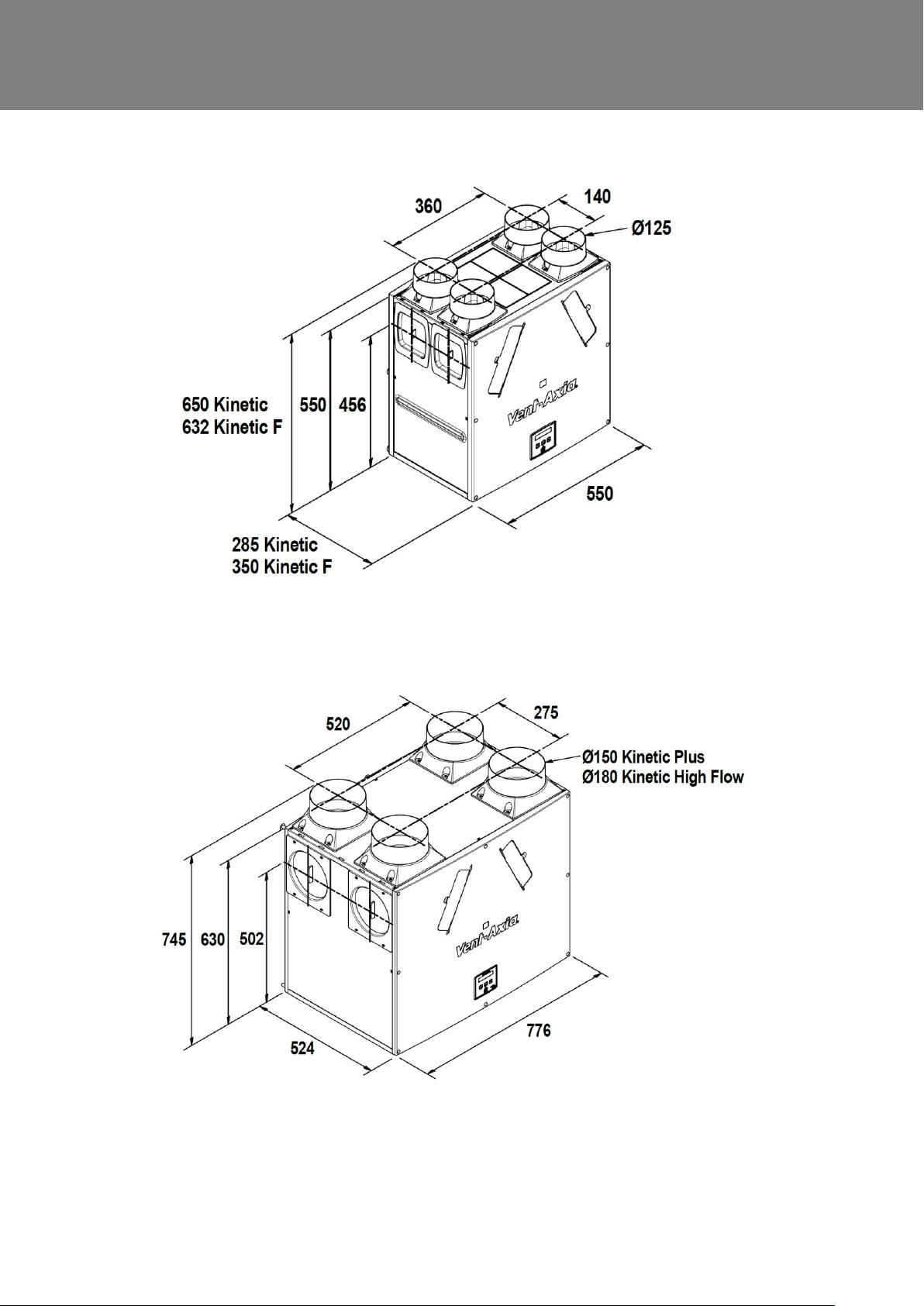
Figure 5: Sentinel Kinetic Dimensions
Figure 6: Sentinel Kinetic Plus and Sentinel Kinetic High Flow Dimensions
Sentinel Kinetic MVHR Installation & Commissioning 7
Page 8
Installation
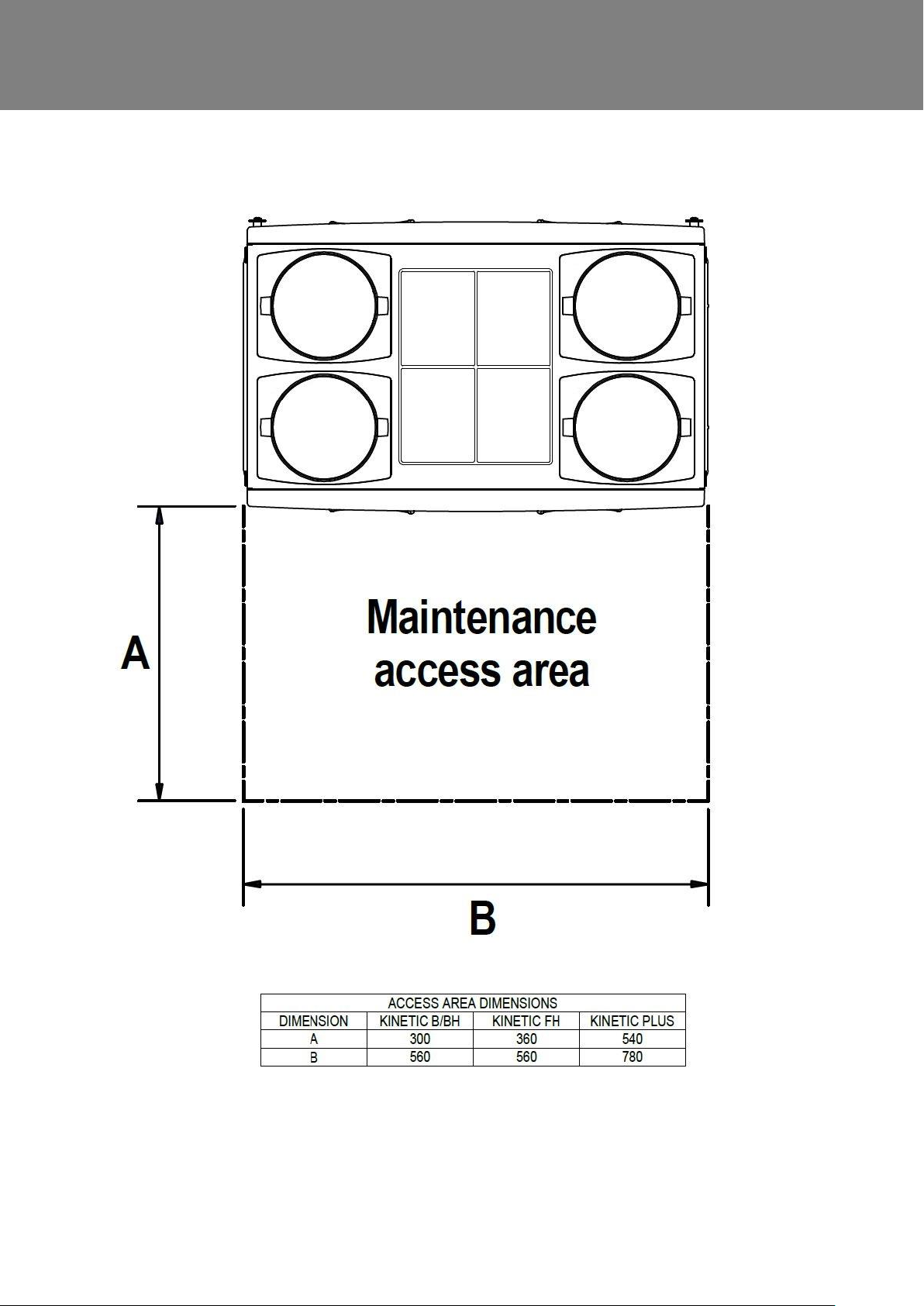
Minimum maintenance access area required in front of kinetic units. (Kinetic Plus & High Flow dimensions the same).
Sentinel Kinetic MVHR Installation & Commissioning 8
Page 9
Installation
0
50
100
150
200
250
300
350
400
450
0 50 100 150 200 250
Volume (l/s)
Static Pressure (Pa)
0
50
100
150
200
250
300
350
400
450
0 10 20 30 40 50 60
492612891185418
253897
75
Volume (m3/h)
20%
40%
60%
80%
100%
0
50
100
150
200
250
300
350
400
0 50 100 150 200 250 300
Volume (m3/h)
Static Pressure (Pa)
0
50
100
150
200
250
300
350
400
450
0 10 20 30 40 50 60 70 80
539627
13
20
304458
12882107
20%
40%
60%
80%
100%
Volume (l/s)
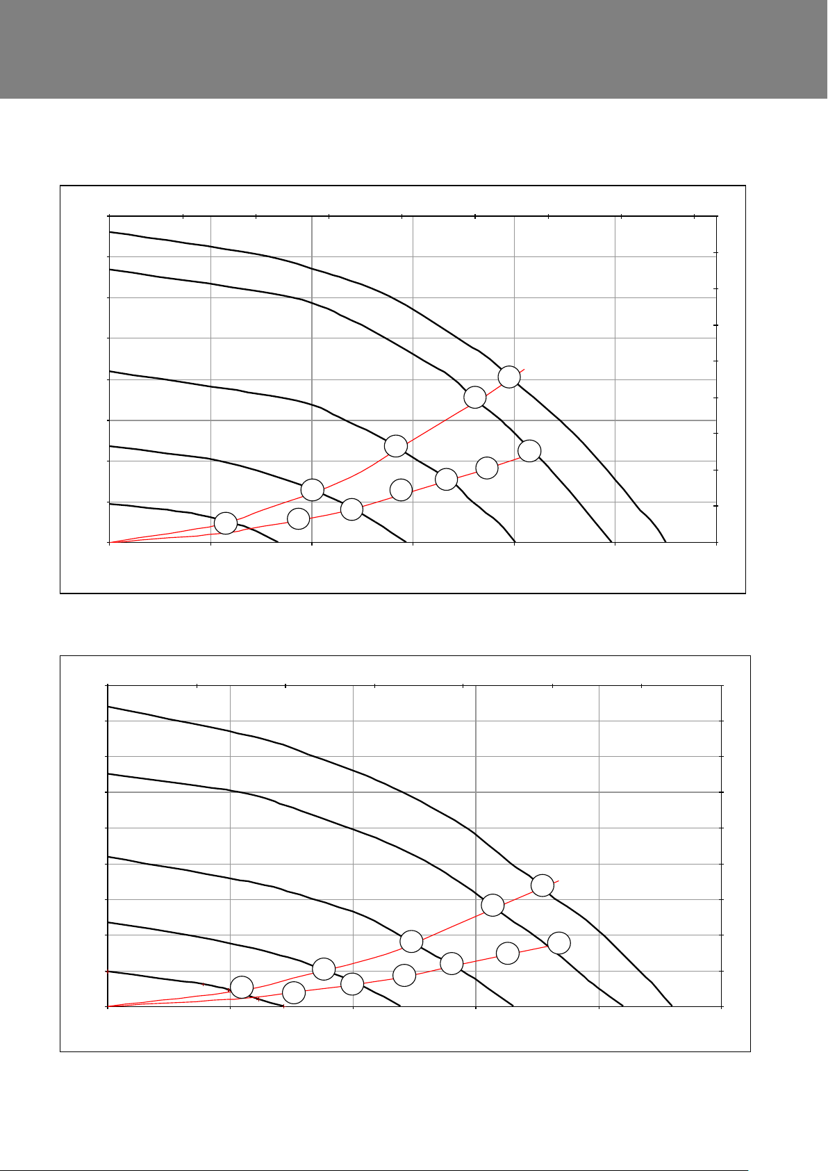
Sentinel Kinetic Performance graph for Vertical Discharge
.
Sentinel Kinetic Performance graph for Horizontal Discharge
Note: Graphs show 2 typical system curves with total unit input power in Watts.
Sentinel Kinetic MVHR Installation & Commissioning 9
Page 10
Installation
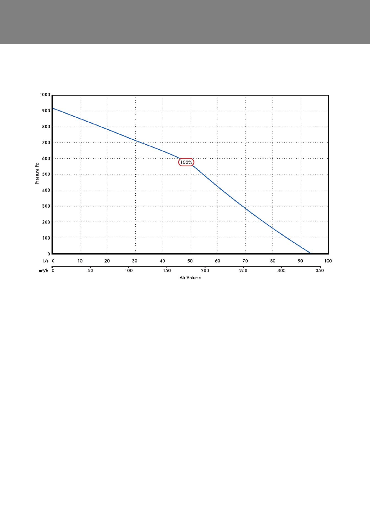
Sentinel Kinetic F Performance graph for Vertical and Horizontal Discharge
Sentinel Kinetic MVHR Installation & Commissioning 10
Page 11
Installation
0 20 40 60 80 100 120 140 160 180
0
100
200
300
400
500
600
700
800
900
1000
0 50 100 150 200 250 300 350 400 450 500 550 600 650 700
Volume (l/s)
Static Pressure (Pa)
Volume (m3/h)
100%
80%
60%
40%
20%
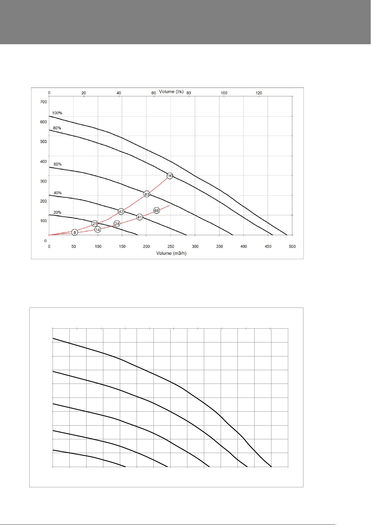
Sentinel Kinetic Plus Performance graph for Vertical and Horizontal Discharge
Note: Graph shows 2 typical system curves with total unit input power in Watts
Sentinel Kinetic High Flow Performance graph for Vertical and Horizontal Discharge
Sentinel Kinetic MVHR Installation & Commissioning 11
Page 12

Installation
Installation
NOTE:
We advise installers to fix all mains and sensor wiring along with any internal accessories prior to fixing
the MVHR unit in position, leaving approximately 500 mm tails to allow for internal routing.
If the orientation of the condensate exit (and the atmosphere spigots) would be better suited on the left
of the unit, the front Control Unit and the rear Cable Inlet Plate can be swopped over to allow the unit to
be installed in the opposite orientation.
Before Installation of the Unit
Inspect the Unit
When taking delivery of the unit, check the items delivered against the enclosed delivery note. Inspect the unit
for damage in transit. If in doubt, contact Customer Services. Each box contains a Kinetic HR unit and an
accessory pack containing wall bracket, condensate drain link pipe, pipe clips and product documentation.
Lift and Move the Unit Safely
On page 7 check the weight of the unit that you are installing. Always use appropriate lifting techniques and
appliances when moving heavy equipment.
Check Site Requirements and Safety Notices
Check that the physical and environmental conditions for the site meet, or exceed, the requirements detailed in
the Technical Specification on page 7.
Read and observe the safety notices listed in Warnings and Safety Information on page 2.
Unit Installation
The wall should have sufficient strength to support the unit.
Take into consideration the position of the electrical services and the condensate drain.
Ensure there is adequate access for installation, operation and maintenance.
It is recommended that a local disconnection mains and sensor terminal box is installed within 1m of the unit to
facilitate future maintenance.
The unit MUST always be mounted vertically with ducting exiting vertically or horizontally. Do not use this unit
as a support for any other equipment.
If installing in a cold void for optimum performance insulate the unit
Sentinel Kinetic MVHR Installation & Commissioning 12
Page 13
Installation
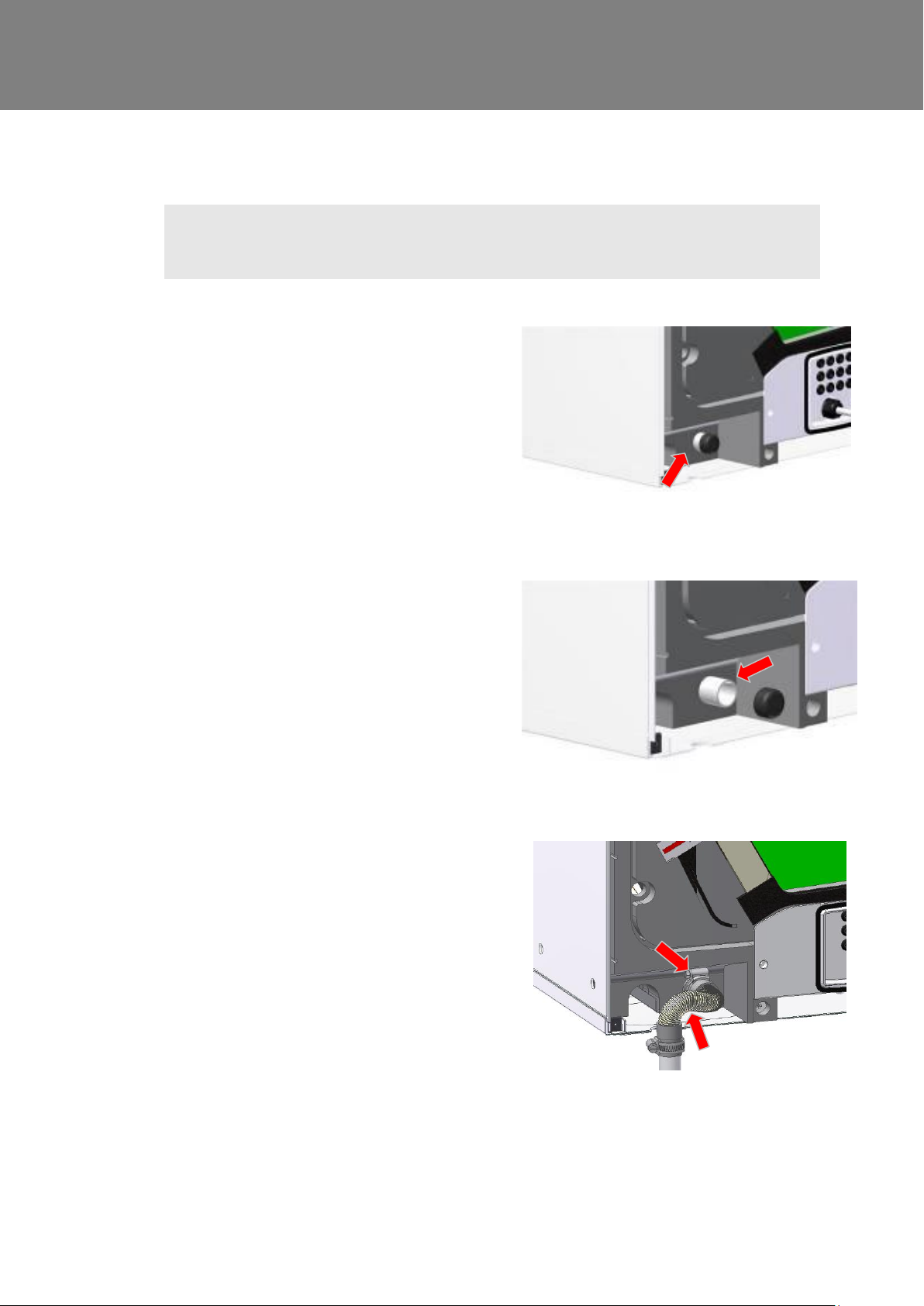
1. For vertical discharge, remove the rear cover and
locate the condensate stub at the rear of the unit.
2. Remove the black Cap from the end of the
condensate stub at the rear of the unit.
3. If not already fitted, fit the flexible condensate pipe
and secure with worm drive clip
The condensate pipe can be attached with a worm
drive clip to a 22 mm vertical pipe.
Fit a ‘U’ bend condensate drain having a minimum
of a 60mm water seal or a HepVo valve to the
building’s foul water drainage system and ensure
there is a minimum 3 degree fall to allow
condensate drainage.
4. Go to Spigot Installation on page 17.
Vertical Discharge Condensate Installation
Note
The 22 mm diameter condensate pipe is suitable for standard 22 mm plastic push-fit fittings and can
be connected vertically underneath the unit or horizontally at the rear.
To install the vertical discharge condensate:
Sentinel Kinetic MVHR Installation & Commissioning 13
Page 14
Installation
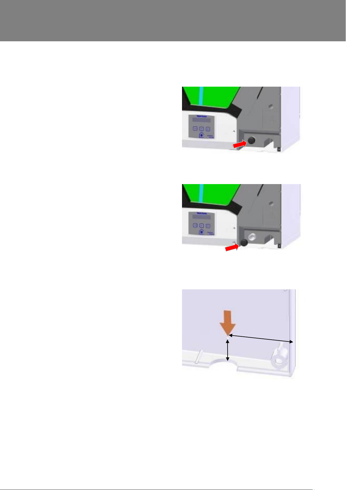
1. For horizontal discharge, remove the front
cover and locate the condensate stub at the
front of the unit.
2. Remove the Black Cap from end of
condensate stub at the front of the unit.
3. On the Kinetic drill a diameter 32 mm hole
where shown, right.
On the Kinetic Plus drill a diameter 32 mm
hole using the indent provided in the
moulding as a guide.
The hole is a clearance hole for a diameter
22 mm pipe and so may vary a little from
this guidance.
60 mm
21 mm
Horizontal Discharge Condensate Installation
To install the condensate horizontal discharge:
Sentinel Kinetic MVHR Installation & Commissioning 14
Page 15
Installation
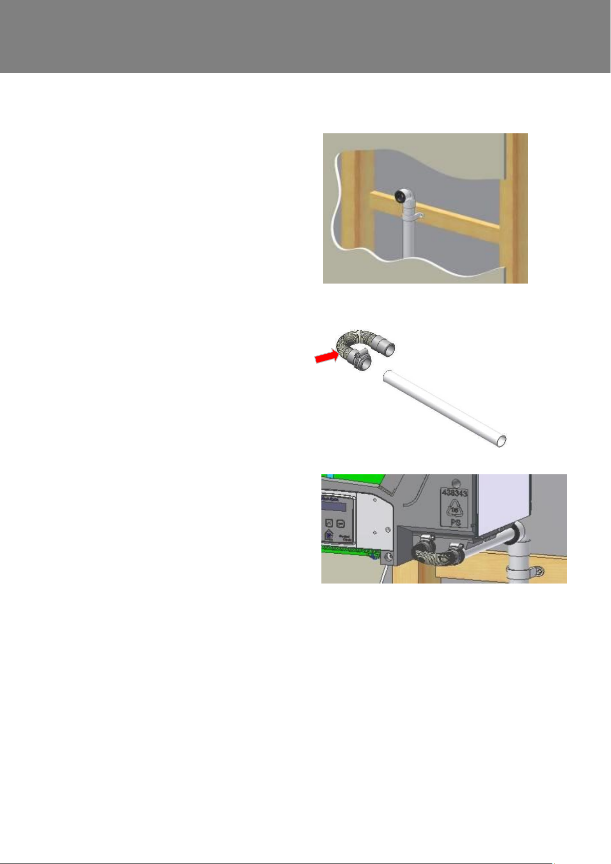
4. N.B. SEE “WALL MOUNTING” on page 18
for information on marking out the wall for
the position of the condensate drain and
wall mounting brackets.
Fit Vertical discharge 32mm waste pipe
(fitted with 22 / 32mm reducer ).
Fit a ‘U’ bend condensate drain having a
minimum of a 60mm water seal or a HepVo
valve to the building’s foul water drainage
system and ensure there is a minimum 3
degree fall to allow condensate drainage.
5. Fit the flexible condensate pipe to a
22mm diameter x 280mm long
condensate pipe with worm drive clip.
6. Fit pipe assembly into waste pipe and
secure to condensate spigot with worm drive clip.
N.B. Always insulate condensate pipe if installing in a cold void
Sentinel Kinetic MVHR Installation & Commissioning 15
Page 16
Installation
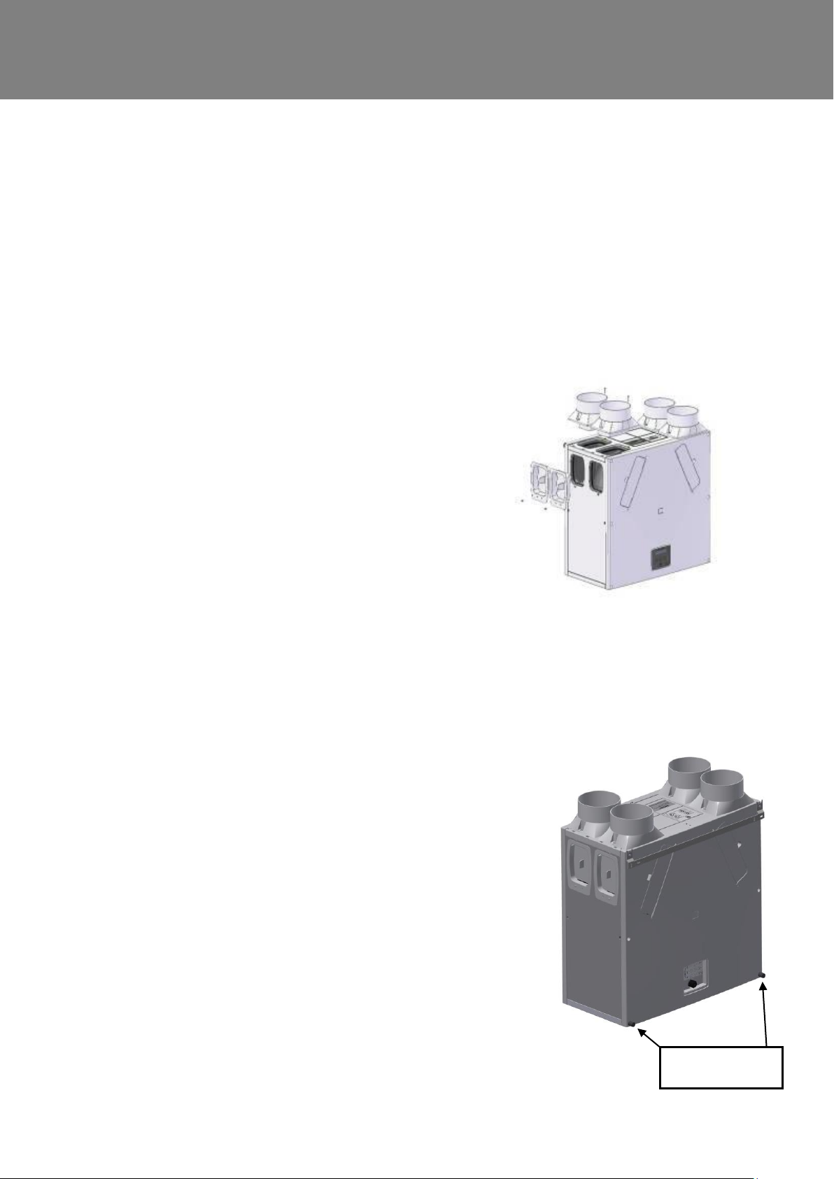
1. Remove the spigot by unscrewing the screw(s)
securing it to the chassis. Then pull the spigot firmly
from the entry/exit hole.
2. Remove the blanking cap by unscrewing the screw(s)
securing it to the chassis. Then pull the blanking cap
firmly from the entry/exit hole.
3. Swap over the spigot with the removed blanking cap.
4. Insert the spigot into the entry/exit hole and secure
with the retaining screw(s).
5. Insert the blanking cap into the entry/exit hole and
secure with the retaining screw(s).
Stand-off feet
Spigot Installation
Air entry/exit spigots may be fitted on either the top or the side of the unit for vertical or horizontal entry or exit. Attach
the spigots, depending on the space available for the ducting and orientation of the unit. Always fit the blanking caps
to the entry or exit hole not in use to ensure the correct airflow into and out of the unit.
Note: Sentinel Kinetic Plus units have spigots suitable for either diameter 150mm ducting (UK model) or for diameter
180mm ducting (rest of EU model). The diameter 180mm spigots come complete with self-adhesive foam adaptors
to enable it to be used with either diameter 180mm ducting or diameter 200mm ducting. These foam adaptors are to
be fixed to the outside of the spigot for diameter 200mm ducting. High Flow units are supplied with 180mm spigots,
an accessory pack of four self-adhesive foam adaptors part no. 409761 is available for use with 200mm ducting.
To move the spigots:
N.B. Before finally fixing the unit into position it may be more convenient to make
the electrical connections; including the mains connections and any wiring
for sensor(s) or switch(es).
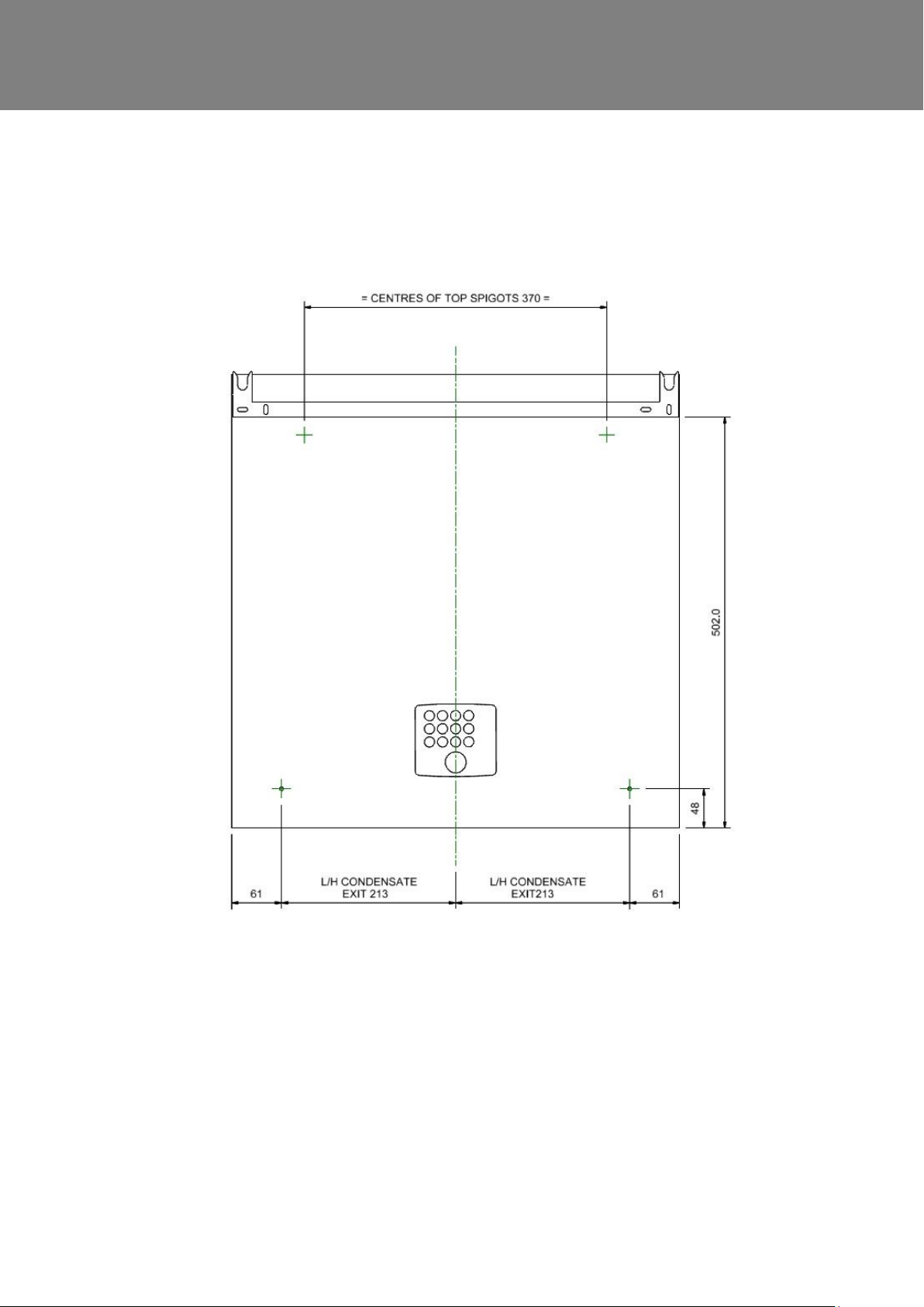
Wall Mounting Sentinel Kinetic & Kinetic F
1. Refit the front and rear covers if they have been removed.
2. Ensure the two steel wall bushes are fitted to the rear cover,
along the top row of screws.
3. Mark the condensate and wall bracket positions.
4. Fit the stand-off feet in place, supplied in the accessory bag.
5. Fit metal wall bracket (supplied) to the wall using appropriate fixings.
6. Lift unit and locate the steel wall bushes onto the wall bracket. The unit
should now be physically installed in its intended operating location.
7. Ensure that the condensate drain is connected as described on page 15.
Sentinel Kinetic MVHR Installation & Commissioning 16
Page 17
Installation
Sentinel Kinetic MVHR Installation & Commissioning 17
Page 18
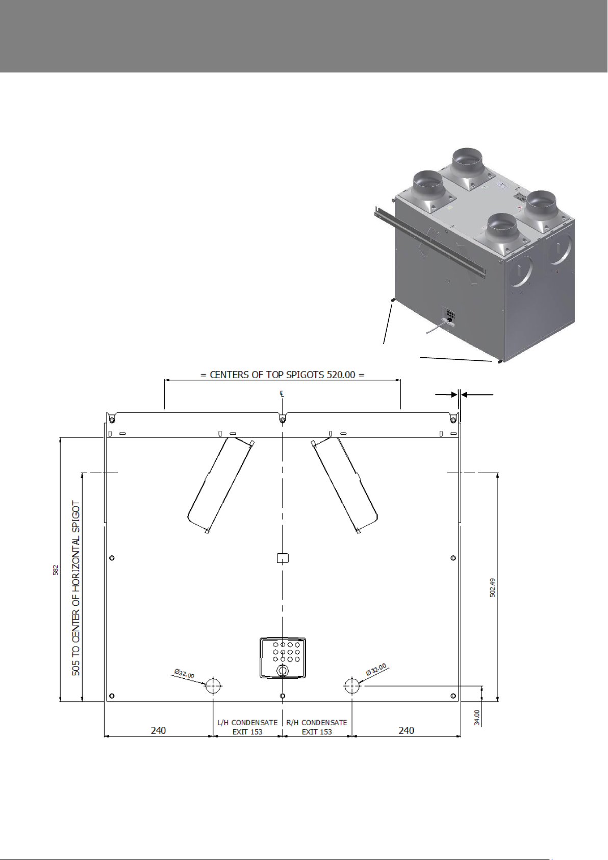
Installation
1. Refit the front and rear covers if they have been removed.
2. Ensure the three steel wall bushes are fitted to the rear cover,
along the top row of screws.
3. Mark the condensate and wall bracket positions using the drawing below.
4. Fit metal wall bracket (supplied) to the wall using appropriate fixings.
5. Fit the stand-off feet in place, supplied in the accessory bag.
6. Lift unit and locate the steel wall bushes onto the wall bracket.
The unit should now be physically installed in its intended operating location.
7. Ensure that the condensate drain is connected as described on page 15.
Stand-off feet
Wall Mounting Sentinel Kinetic Plus & Sentinel Kinetic High Flow
Sentinel Kinetic MVHR Installation & Commissioning 18
Page 19
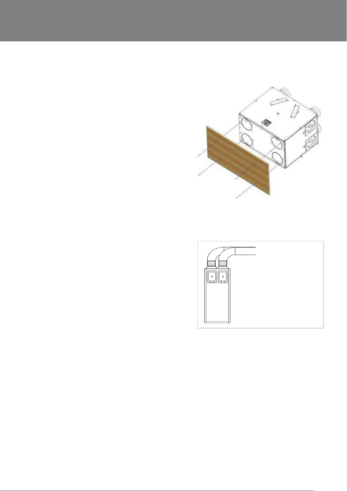
Installation
1. Remove the front and rear covers.
2. Ensure that a secure, firm, flat and level surface is
provided to place the Kinetic Plus unit on.
3. Screw down through the white plastic base plate of the
unit to a board which may then be screwed to joists,
flooring or equivalent.
4. The unit should now be physically installed in its
intended operating location.
1. Always use a short piece of flexible duct 100-150 mm
long, extended to its full length when connecting to
ductwork.
2. Securely connect this ducting to the spigots using
worm-drive clips or cable ties.
3. Insulate all ducting running to and from atmosphere and
any ducting that passes through an unheated space.
Floor Mounting Sentinel Kinetic Plus and Kinetic High Flow
Attach the ducting:
Sentinel Kinetic MVHR Installation & Commissioning 19
Page 20
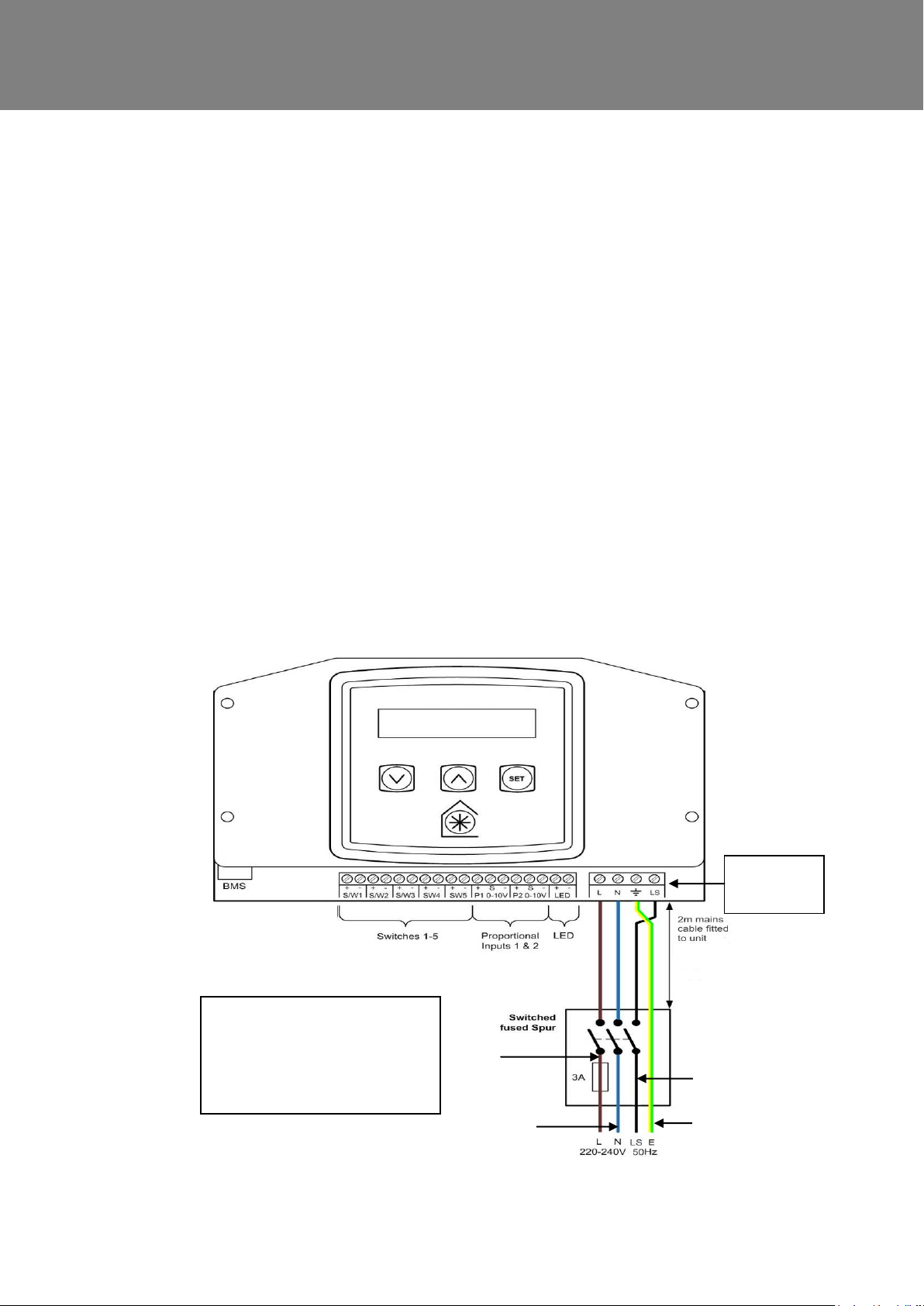
Installation
Brown
Blue
Green/Yellow
Black
Other means of connecting the
unit can be used if they meet
the local wiring regulations.
SEE NOTES ON PAGE 22
Connection
on Rear
Electrical Installation
Connect Switches and Sensors
The unit can be switched to boost by a variety of methods:
Applying 240 V to the LS input .
Switching across 1 of 5 pairs of switch terminals.
Applying between 0 and 10 V as a proportional input to two input terminals.
N.B Alternative functions are assigned to SW/1, SW/2, SW/3 & SW5 when Control Mode 02 is selected in
the start-up screens see Appendix One for further details.
Terminal 4 can be used in conjunction with a momentary switch or switches.
Connect any switches or sensors required to control the unit by connecting to the terminal connectors at the
bottom of the control unit as shown below and in Table 1. If necessary contact Vent-Axia regarding the wiring
and fixing of accessories and sensors.
The cable entry back plate may have grommets or easy knock-out positions. If the knock-outs are used then
ensure that you use a grommet or gland to protect against potential water ingress.
When fitting external controls the appropriate cord anchorage and glands, according to country
requirements for cable size should be fitted, these glands should have a minimum water ingress
protection of IPX2.
Sentinel Kinetic MVHR Installation & Commissioning 20
Page 21
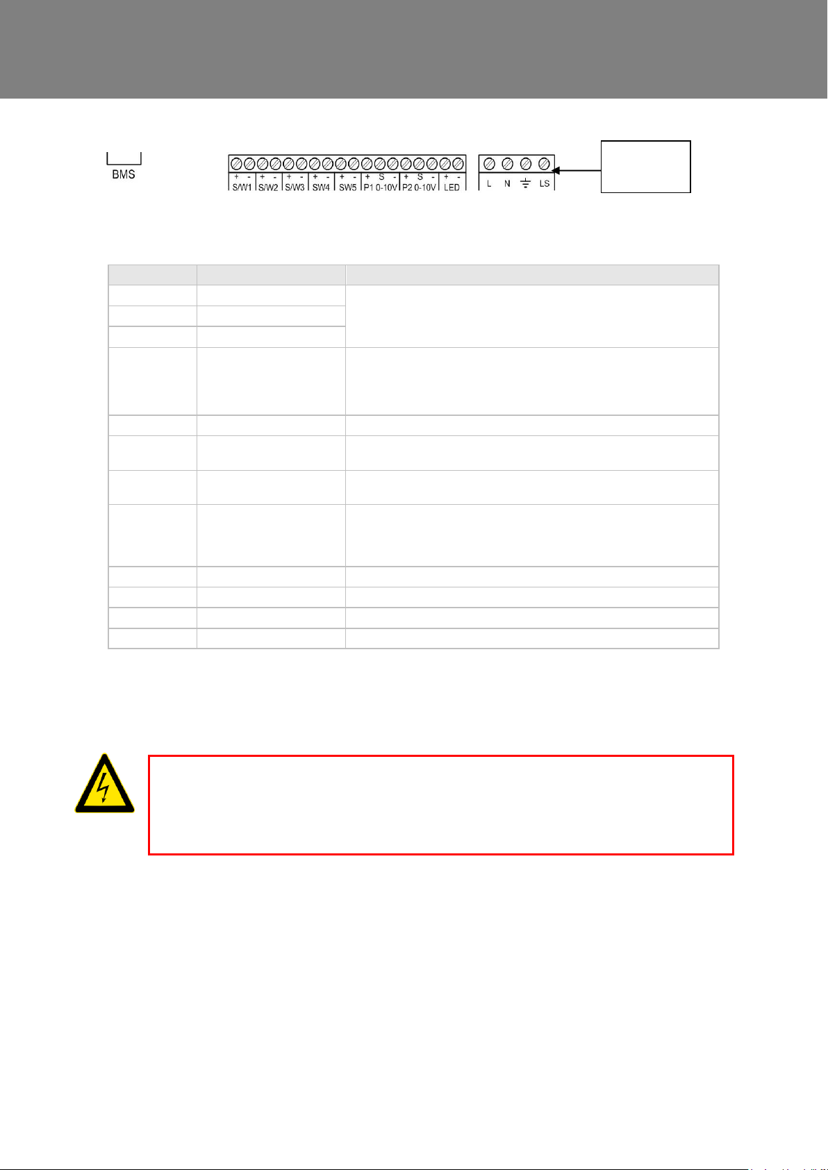
Installation
Terminal No.
Name
Description (Control Mode 01)
S/W1
Switch 1
With link fitted on J4 - activates volt-free contact for sensor input
between + and - terminals
S/W2
Switch 2
S/W3
Switch 3
SW4
Switch 4
Volt-free contact for sensor input between + and – terminals
(Momentary if SW/4 if SW4 Commissioning Screen set On)
With Vent-Wise PCB fitted to J4 - enables Vent-Wise momentary switch
input
SW5
Switch 5
Volt-free contact for sensor input between + and - terminals
P1 0-10V
Proportional 1
A 24 V DC sensor supply is output between the + and - terminals.
A 10 V proportional sensor input is received between S and - terminals
P2 0-10V
Proportional 2
A 24 V DC sensor supply is output between the + and - terminals.
A 10 V proportional sensor input is received between S and - terminals
LED
Red Light Emitting Diode
Output
A LED driving signal output between the + and – terminals that enables
remote indication of a unit fault. See the Control Panel for fault code
(see Service/Fault Code Screens on page 42). Also used for as
connection to a BMS or similar.
L
Mains Live
220-240 V AC, 50 Hz input
N
Mains Neutral
220-240 V AC, 50 Hz input
EARTH
Mains Earth
Earthing connector
LS
Switched Live
220-240 V AC, 50 Hz input
Connection
on Rear
Table 1: Terminal Connections
N.B Alternative functions are assigned to SW/1, SW/2, SW/3 & SW/5 when Control Mode 02 is selected in the start-up screens
see Appendix One for further details
Connect the Power Supply
WARNINGS
1. MAINS SUPPLY VOLTAGES (220-240 V AC) ARE PRESENT IN THIS EQUIPMENT WHICH MAY CAUSE
DEATH OR SERIOUS INJURY BY ELECTRIC SHOCK. ONLY A QUALIFIED ELECTRICIAN OR INSTALLER
SHOULD CONNECT THE POWER SUPPLY TO THIS UNIT.
2. THIS UNIT MUST BE CORRECTLY EARTHED.
This unit is designed for operation from a single-phase alternating current source (220-240 V AC). A 1.5 m cable
is connected internally to the unit for connection to an isolator switch.
To connect the power supply:
Ensure the local AC power supply is switched off.
One end of the power cable supplied is already connected to the unit and routed through the Cable Inlet
Plate via a suitable gland to ensure the IP rating of the unit is not affected.
Connect the other end of the cable to the switched fused spur.
Use cable clamps and clips to secure the cable, as appropriate.
Sentinel Kinetic MVHR Installation & Commissioning 21
Page 22

Installation
Connecting a Boost (Light) Switch
A Switched Live (LS) may be used to boost the airflow when a light is turned on, for instance in a bathroom or
kitchen. If the LS core of the mains cable is not used it should be terminated in an appropriate manner.
NOTES
Power supplied to the unit via a 3 pole isolating switch, such as Vent-Axia Part Number 563518, must be supplied
via the same circuit as the LS connection. Alternatively an isolator relay controller, part number 442030, may be
used. The live supply to the unit should be fused at 3A.
Example wiring diagrams are available via Vent-Axia Technical support, e.g. Drawing Number 448144.
Sentinel Kinetic Range Summer By Pass Models.
The Sentinel Kinetic B, BH, Plus B, Plus BS and S BH are fitted with a Summer By Pass (SBP) and will provide
energy-free cooling when the house temperature and ambient temperature allows.
Note that the volume of air provided by this ventilation system is a fraction of that required for space heating or
space cooling and will not in itself be sufficient to cool a room. It will however, provide a contribution and make a
difference.
There are three operating modes, Normal, Evening Purge and Night-time purge.
Normal Mode.
Air flow rate is determined by sensors, boost and timing settings, otherwise is normal rate.
If the room is warmer than the set (shown as "indoor") temperature (i.e. you need the room to be cooler) and the
outdoor air is cooler than the actual room temperature (i.e. the outdoor air could cool your room) then the SBP will
open and the unit will supply cooler air to your room.
Note that the above only applies whilst the outdoor air temperature is above 14 C (adjustable) in order to prevent
cold draughts.
The set ("indoor") temperature should be set 2 or 3 degrees higher than the central heating thermostat and 2 or 3
degrees below any air conditioning thermostat if fitted. This will prevent any clash between the separate systems.
Evening purge Mode.
Intended for use as the outdoor temperature cools in the evening, but reverts to normal control after a set time so
that any increase in noise is avoided overnight.
Air flow rate is always at boost.
The bypass closes and the purge stops if the temperature conditions described in Standard Mode are no longer
met or 5 hours after the bypass opened.
Night-time purge Mode.
Intended for use as the outdoor temperature cools in the evening and continues through the night when cooling is
a higher priority than any increase of noise. Note that the air noise in your system is influenced by the ducting
design and layout and the size and type of vents used in the rooms. If improvements are required speak to your
installer.
Air flow rate is boost.
The bypass closes and the purge stops if the temperature conditions described in Standard Mode are no longer
met.
Sentinel Kinetic MVHR Installation & Commissioning 22
Page 23
Commissioning
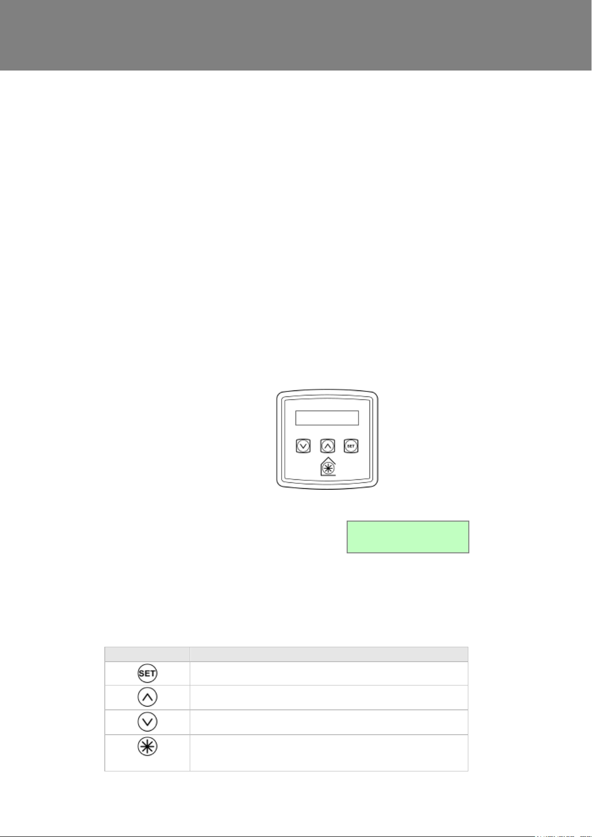
The main display is a 16 character by 2-line liquid crystal
display (LCD) with automatic backlight, which is turned
off to automatically minimise power consumption.
Normal Airflow
30%
Button
Function
Press to adjust settings and press to save settings.
Press to go to the previous screen or to increase a parameter value. Press
and hold for more than 2 seconds for fast scrolling.
Press to go to the next screen or to decrease a parameter value. Press and
hold for more than 2 seconds for fast scrolling.
Press to activate Boost mode. See page 25 for options.
Press and hold for 5 seconds to activate Purge mode. (Press and hold for 5
seconds to cancel Purge).
Powering Up the Unit
Switching On
To switch the unit on:
1. Switch on the power at the mains supply isolator feeding the unit.
2. Following switch-on, the fan motors will start and the Control Unit will display a series of start-up screens,
described below (see Start-up Screens on page 24).
3. N.B. If you are intending to carry out work or maintenance inside the unit, switch off the power at
the mains outlet supplying the unit before you remove the covers.
Switching Off
To switch the unit off:
1. Turn the power off at the mains supply isolator.
Control Unit Display
The Control Unit is located at the front of the Sentinel Kinetic unit. The Control Unit provides the user interface
for commissioning and monitoring purposes.
Display
Buttons
Four buttons on the Control Unit provide the controls for configuring and monitoring the unit.
Sentinel Kinetic MVHR Installation & Commissioning 23
Page 24
Commissioning
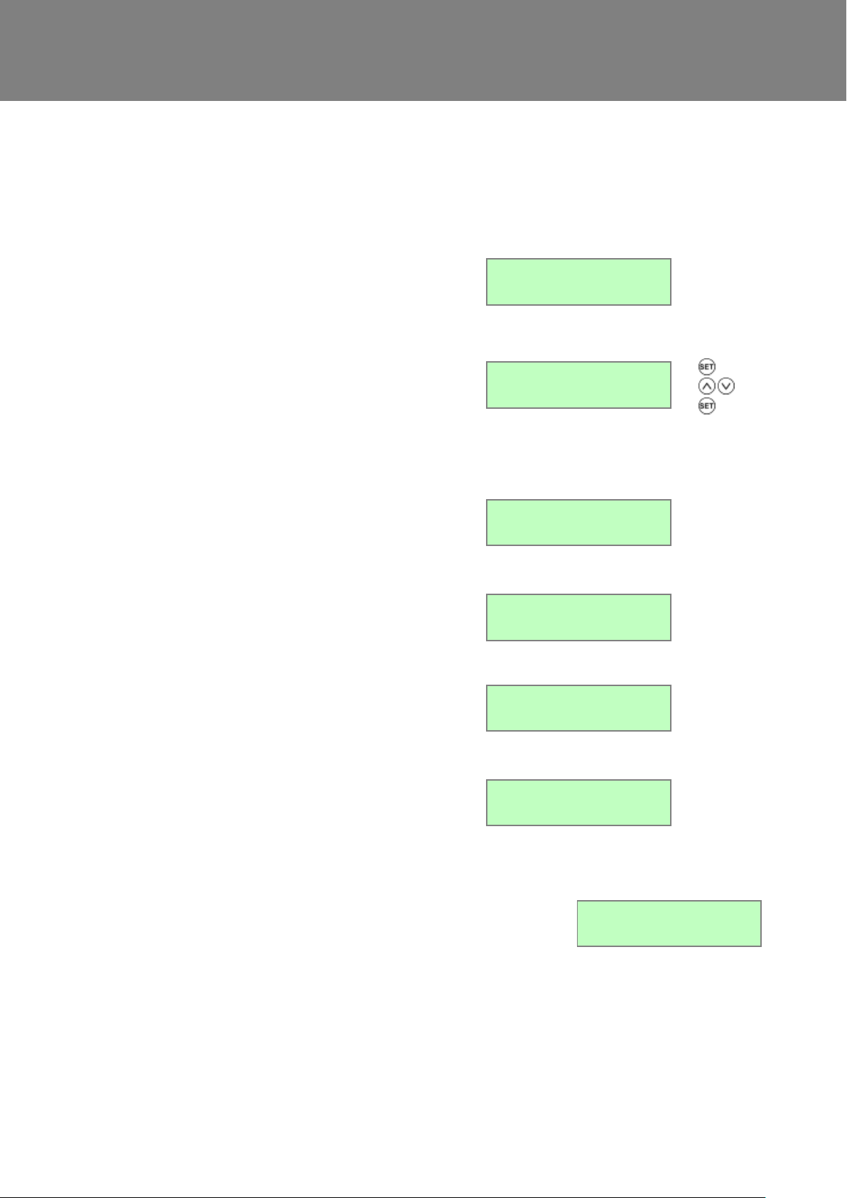
The Sentinel Kinetic Version screen displays the
firmware version number for 3 seconds.
No adjustments are possible on this screen.
Loading...
The Language screen displays the language used for
the screens. It is typically displayed for 5 seconds, or
longer if changing the setting.
(To re select a new language disconnect and then
reconnect to the mains supply).
Control Mode Screen
Language
English
Selects between Control Mode 01 operation described
herein and the alternative Control Mode 02 described
in Appendix One.
Control Mode
01
The Airflow Units is a percentage of the unit’s
maximum flow.
Airflow Units
%
The Wireless Control screen automatically displays
whether the wireless boost control switch is fitted. It is
typically displayed for 3 seconds.
Wireless Control
Not Fitted
The Humidity Sensor screen displays whether the
humidity sensor is fitted. It is typically displayed for
3 seconds.
Humidity Sensor
Not Fitted
When the start-up screens are finished, the low or normal screen is
displayed showing operating status (Low Airflow X % or Normal Airflow
X % or Boost Airflow X %).
The Normal screen displays the rate of normal airflow (supply air)
through the unit.
If the installation has proportional sensors or an internal humidity
sensor fitted, and any of these are boosting the airflow, an α symbol
will be displayed.
Normal Airflow
30 %
Start-up Screens
(Refer to Control Mode 01 unless otherwise indicated)
Sentinel Kinetic Version Screen
Language Screen
Airflow Units Screen
Wireless Control Screen
Humidity Sensor Screen
Low Airflow / Normal Airflow / Boost Airflow Screen
Sentinel Kinetic MVHR Installation & Commissioning 24
Page 25
Commissioning
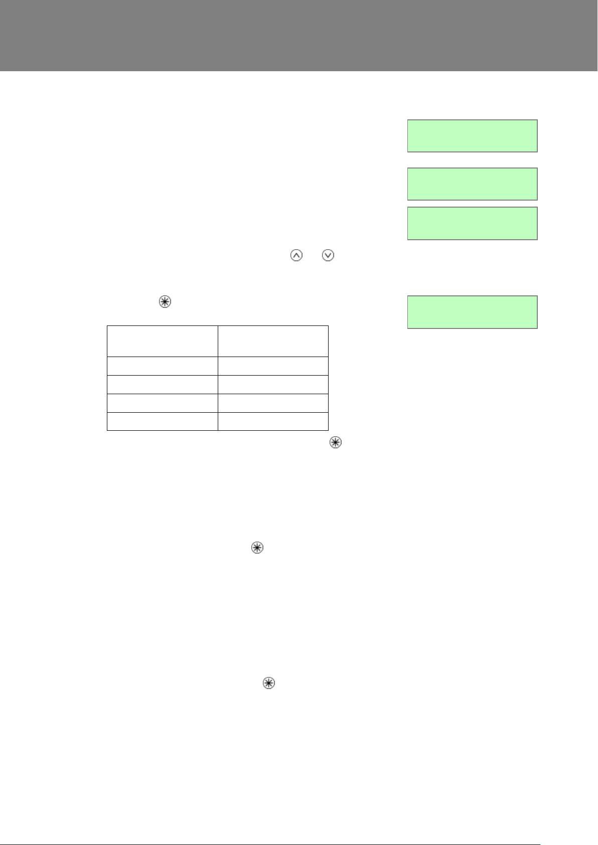
If Control Mode 02 has been selected then the Normal Airflow screen
includes either “Auto” or “Manual” to indicate if the boost level has been
triggered by the button on the controller or automatically via a sensor.
Normal Airflow
30% Auto
When the summer bypass is active, the normal screen top line will
alternate (for 3 seconds) with Summer Bypass On.
Summer Bypass On
30 %
An interval can be set, see page 40, at which the unit reminds the user
to check the filters. The normal screen top line will include Check Filter
as a reminder to check and, if necessary, clean or replace the filters.
When this has been done, press and hold the and buttons for 5
seconds to reset the automatic message.
Check Filter
30 %
Pressing the button activates the boost airflow mode when extra
ventilation is required.
No. of presses
Boost action
(Control Mode 01)
1
Boosts for 30 minutes
2
Boosts for 60 minutes
3
Boosts continuously
4
Back to Normal flow rate
N.B Additional airflow modes are available from the button
when Control Mode 02 is selected in the start-up screens see
Appendix One for further details.
If the wireless boost option is fitted, this can be triggered from the
wireless transmitter/boost switch.
If the installation has switch sensors, is wired to the lighting, has VentWise sensors, Vent-Wise momentary switch or if the internal time
switch is set for periodic operation, operation will change from normal
to boost automatically. Pressing the button will reveal a code to
show which device has activated boost.
s1 = Switch S/W1
s2 = Switch S/W2
s3 = Switch S/W3
s4 = Switch SW4
s5 = Switch SW5
ls = Switched live (LS)
c1-3 = Internal Time switch
If running on boost due to pressing the button, another device may
‘take over’ the boost. Flow will return to normal when that device
switches off. If a number of different devices are calling for boost flow,
the unit will run at boost until the last one has reverted to normal.
N.B Alternative functions are assigned to S/W1, S/W2, S/W3 &
SW5 when Control Mode 02 is selected in the start-up screens see
Appendix One for further details.
Boost Airflow
50 %
Sentinel Kinetic MVHR Installation & Commissioning 25
Page 26
Commissioning
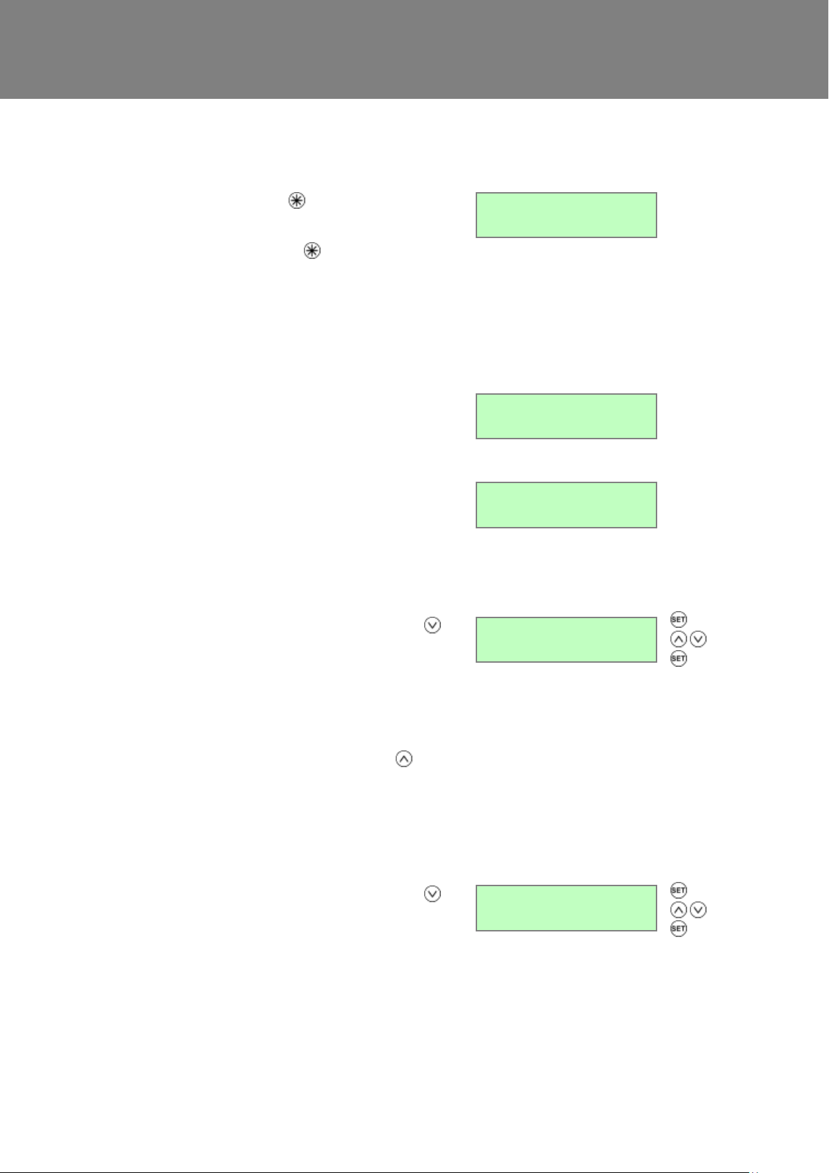
Pressing and holding the button for approximately 5
seconds activates purge mode when you want to purge
air from the building. The unit will revert to normal flow
by pressing and holding the button again for 5
seconds. If the wireless boost option is fitted, purge can
be triggered from the wireless transmitter/boost switch.
Purge mode runs the fans at full speed for 2 hours (120
minutes). The Purge screen displays a countdown of
the time remaining.
Purge 120m
100 %
Cooker Hood mode is activated when the J12, LS input
is activated, see page 34 for details.
Cook Hood
100 %
Low Airflow mode is activated when the Normal Airflow
is set to Off, (see page 33 for set up details).
The Normal Airflow mode can be set to run during the
daytime i.e. from 6am to 11pm, the Low Airflow mode
will then run during the night from 11pm to 6pm.
Low Airflow
20 %
From the Normal Airflow screen, simply press the
button once to access the Set Clock screen.
The Set Clock Control screen enables you to change
the clock settings. The clock retains its settings for
approximately two weeks without mains power, after
which it will need resetting when power is reconnected
Values are DDD HH:MM.
Return to the normal display by pressing the button
or leave to timeout and return automatically after 2
minutes.
The unit will not automatically switch for daylight saving
time.
Set Clock
Mon 12:30
From the Normal Airflow screen, simply press the
button twice to access the Summer Bypass screen.
If the unit is a summer bypass model, the Summer
Bypass screen enables you to switch the summer
bypass control on or off. This screen is only displayed
when the bypass is fitted. See Page 9 for a
description of this function.
Options available are Normal (default), Evening
Purge, Night time purge and Off.
Summer Bypass
Normal
Purge Screen
Cooker Hood Boost Screen
Low Airflow Screen
Set Clock Screen
Summer Bypass Screen
Sentinel Kinetic MVHR Installation & Commissioning 26
Page 27
Commissioning
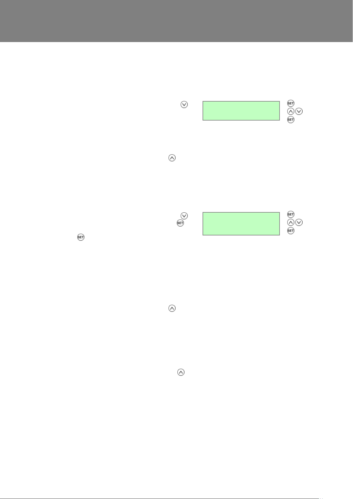
From the Normal Airflow screen, simply press the
button until the Indoor Temp screen is displayed.
The Indoor Temp screen enables you to choose the
target room temperature in degrees Centigrade – only
displayed when the bypass is fitted.
Selectable range is 16-40 (25 default).
Return to the normal display by pressing the button
or leave to timeout and return automatically after 2
minutes.
This function will only work when the Summer Bypass
is set to on.
Indoor Temp
25 C
Outdoor Temp Screen
From the Normal Airflow screen, simply press the
button until the Indoor Temp is displayed. Press
button to choose the required temperature and then
press button again to confirm the entry and this will
call up Outdoor Temp.
The Outdoor Temp screen enables you to choose the
minimum outdoor temperature at which the bypass will
operate in degrees Centigrade – only displayed when
the bypass is fitted.
Use this to prevent cold draughts being introduced.
Selectable range is 5C – 20C (14C default).
Return to the normal display by pressing the button
or leave to timeout and return automatically after 2
minutes.
This function will only work when the Summer Bypass
is set to on.
Return to the normal display by pressing the
button or leave to timeout and return automatically
after 2 minutes
Outdoor Temp
14 C
Indoor Temp Screen
Sentinel Kinetic MVHR Installation & Commissioning 27
Page 28
Commissioning
Commissioning
Overview
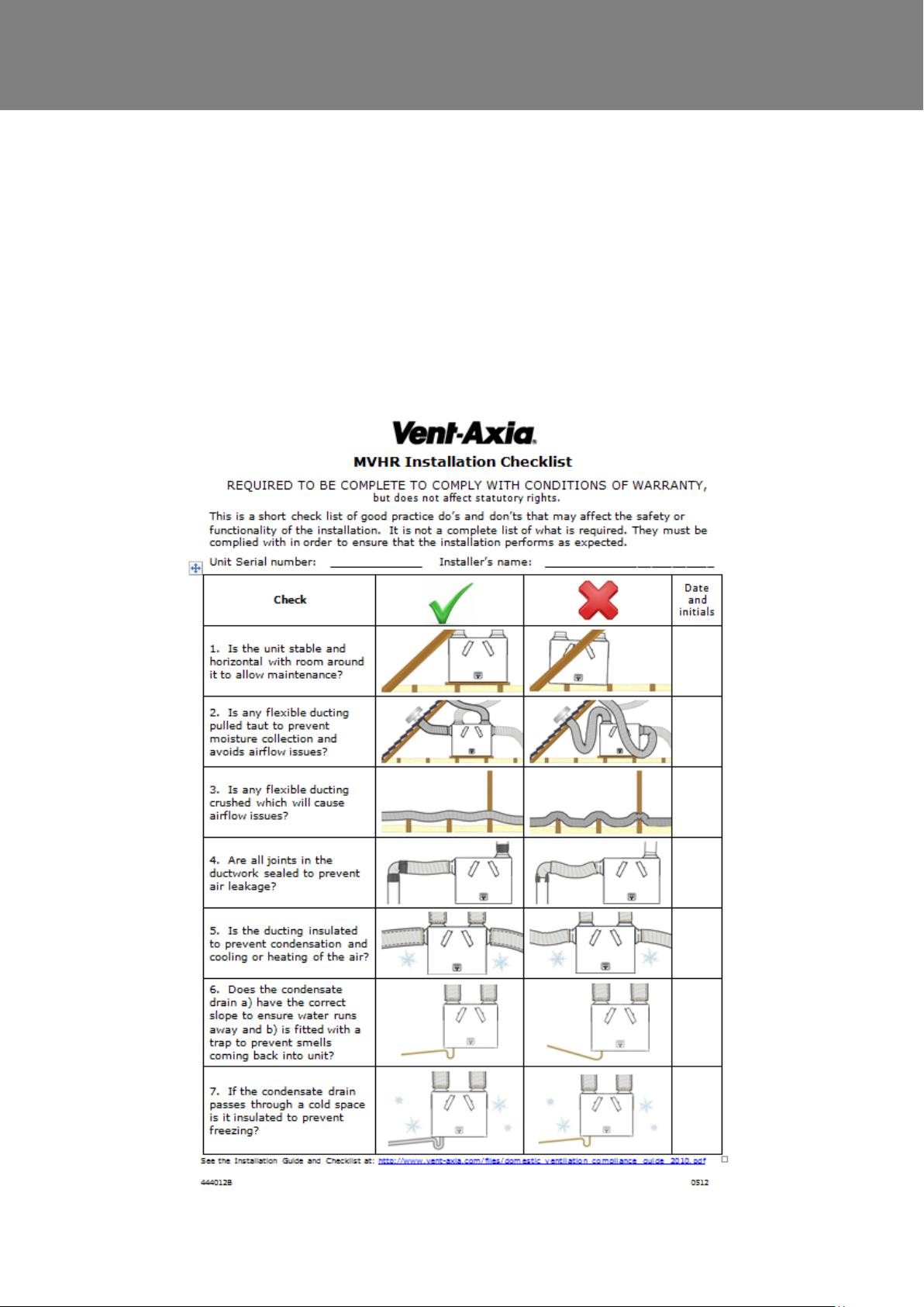
The instructions in this section are intended to provide configuration and operation information for setting up the
equipment. In the event of problems, see Troubleshooting on page 45
Follow good practice when commissioning the unit. Ensure that the system is installed according to the system
designers intent incorporating any acoustic ducting, that all joints are air tight, ducting is well supported, bends
are avoided close to vents, and that the vent valves are fully open at the start of the commissioning process.
The following is attached to the unit and should be used as a checklist prior to setting the air flows.
Sentinel Kinetic MVHR Installation & Commissioning 28
Page 29
Commissioning
PIN number not set
PIN number set
Filter Service
Suburban
Sub-menus
Summer Bypass
Not Fitted
Antifrost
Airflow Mode
Dryout
Off
Running Time
12345
BMS 00
Security PIN?
BMS Mode
On
Proportional 2
CO2
Sub-menus
SW4 Momentary
Off
Sub-menus
Proportional 1
Humidity
Sub-menus
Security PIN?
****
Boost Supply
50 %
Boost Extract
50 %
Normal Supply
30 %
Normal Extract
30 %
Low Supply
20%
Low Extract
20%
Ckr Hood Supply
30 %
Ckr Hood Extract
100 %
Comfort Mode
Boost Overrun
15 m
Boost Delay
00 m
Boost On Off
Mon1 00:00 00:00
Set Service No
Boost On Off
All Set
Normal On Off
Mon 00:00 00:00
Normal On Off
All Set
Boost Button
On
Sub-menu
Restore Defaults
No
Pre Heater
Off
Indoor Temp
25 C
Press
for > 5 s
Press for
Boost
Timeout after 2 minutes
Press
User Menu
Screens
Commissioning Screens
Timeout after 2 minutes
Press for
>5 s to exit the
commissioning
screens
V--
Airflow Units
%
Wireless Control
Not Fitted
Humidity Sensor
Not Fitted
Normal Airflow
30%
Set Clock
Mon 12:30
Summer Bypass
On
Purge 120m
100%
Boost Airflow
50%
Start-up Screens
Low Airflow
20%
CookerHood
100%
Outdoor Temp
14 C
Language
English
Control Mode
01
Anti-frost x
active
N.B.
Anti-frost 1 air flow mode
Anti-frost 2 bypass mode
Anti-frost 3 pre-heater and air flow mode
Anti-frost 4 pre-heater and bypass mode
*Currently Unavailable option
*
Humidity Sensor
Off
Reset Filter?
Filter Reset!
SW5 Flow
Press
for > 5 s
+
Set
RH RR Overrun
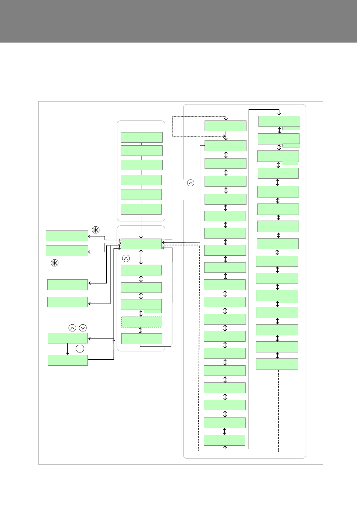
Control Unit Screens Summary
When the unit is switched on (see Powering up the Unit on page 24, the following Control Unit screens are
available for monitoring and configuring the unit.
Sentinel Kinetic MVHR Installation & Commissioning 29
Page 30
Commissioning
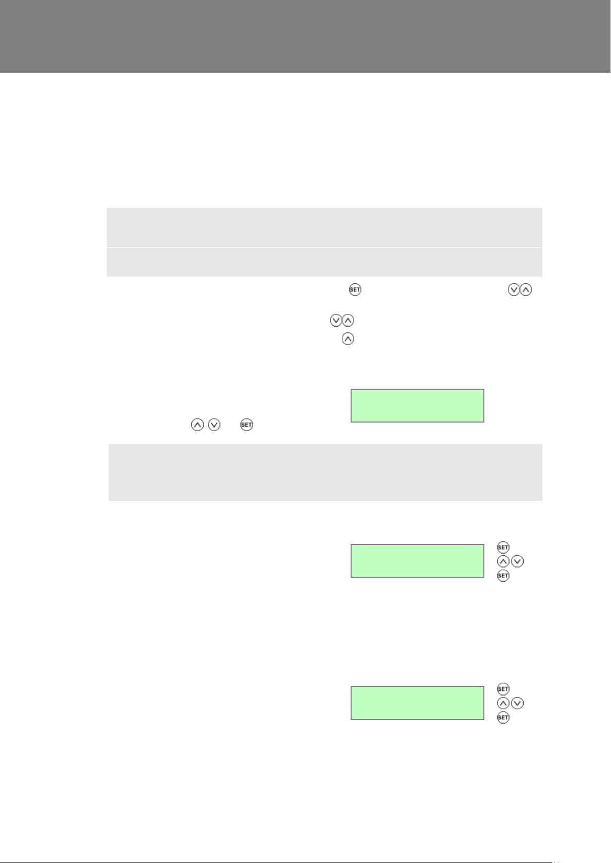
If a security PIN code has been previously set, this
screen will display ****.
Enter the PIN using , and buttons.
Security PIN?
****
The Boost Supply screen enables you to set the Boost
airflow speed for the Supply fan in order to balance out
any differences in ductwork or other installation
features.
Default Boost speed = 50%. See graph on page 10,11
or 12 for setting the Supply airflow.
The Boost speed cannot be set above the Cooker
Hood speed or below Normal speed setting.
Boost Supply
50 %
The Boost Extract screen enables you to set the
Extract airflow speed for the Extract fan in order to
balance out any differences in ductwork or other
installation features. Default Boost speed = 50%. See
graph on page 10, 11 or 12 for setting the Extract
airflow.
The Boost speed cannot be set above the Cooker
Hood speed or below Normal speed setting.
Boost Extract
50 %
Control Unit Screens Overview
Commissioning Screens
The commissioning screens enable you to configure the operational settings of the unit. Settings are stored in a
non-volatile memory and will be retained irrespective of mains supply breaks.
Note: Access to the commissioning screens is prevented if the display shows Antifrost Active, Room
Too Cold or a Fault Code. In this event, switch the unit off and on again and enter the commissioning
screens within one minute. If you are within the commissioning screens the Antifrost and Room Too
Cold Failures modes will not operate allowing the flow rates to be adjusted even in a property which is
below 5C. For further information see Troubleshooting on page 42.
To access the commissioning screens: Press and hold the button immediately followed by the buttons
together; continue to hold down all three buttons for 5 seconds.
To scroll through the Commissioning Screens use the buttons.
To return to the normal screen, either press and hold the button to reach the first menu item and then hold
for a further 5 seconds. Alternatively, the normal display will resume if no buttons are pressed for two minutes.
Security PIN Screen
Note 1
Whilst displaying the Low, Normal, Boost Supply, Low, Normal, Boost Extract screens the fans will run
at the displayed % flow and the bypass will remain shut. The two minute automatic return to normal
display time is extended to four hours to allow time for measurements or adjustments.
Boost Supply Screen
Boost Extract Screen
Sentinel Kinetic MVHR Installation & Commissioning 30
Page 31
Commissioning
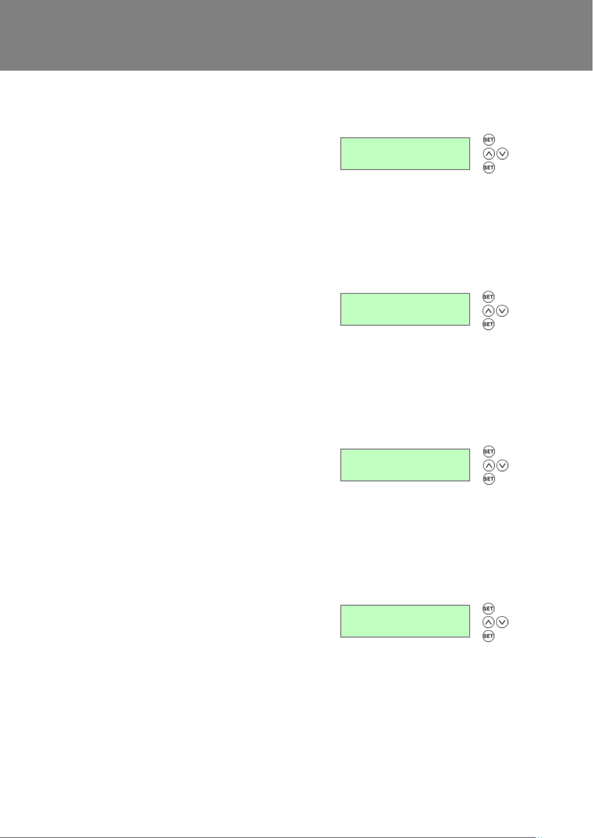
The Normal Supply screen enables you to set the
Normal airflow speed for the Supply fan in order to
balance out any differences in ductwork or other
installation features.
Default Normal speed = 30%
See graph on either page 10, 11 or 12 for setting the
Supply airflow.
The Normal speed cannot be set below Low speed or
above Boost speed setting.
Normal Supply
30 %
The Normal Extract screen enables you to set the
Normal airflow speed for the Extract fan in order to
balance out any differences in ductwork or other
installation features.
Default Normal speed = 30%
See graph on either page 10, 11 or 12 for setting the
Extract airflow.
The Normal speed cannot be set below Low speed or
above Boost speed setting.
Normal Extract
30 %
The Low Supply screen enables you to set the Low
airflow speed for the Supply fan in order to balance out
any differences in ductwork or other installation
features.
Default Low speed = 20%
See graph on either page 10, 11 or 12 for setting the
Supply airflow.
The Low speed cannot be set below 1% or above
Normal speed setting.
Low Supply
20 %
The Low Extract screen enables you to set the Low
airflow speed for the Extract fan in order to balance out
any differences in ductwork or other installation
features.
Default Low speed = 20%.
See graph on either page 10, 11 or 12 for setting the
Extract airflow.
The Low speed cannot be set below 1% or above
Normal speed setting.
Low Extract
20 %
Normal Supply Screen
Normal Extract Screen
Low Supply Screen
Low Extract Screen
Sentinel Kinetic MVHR Installation & Commissioning 31
Page 32
Commissioning
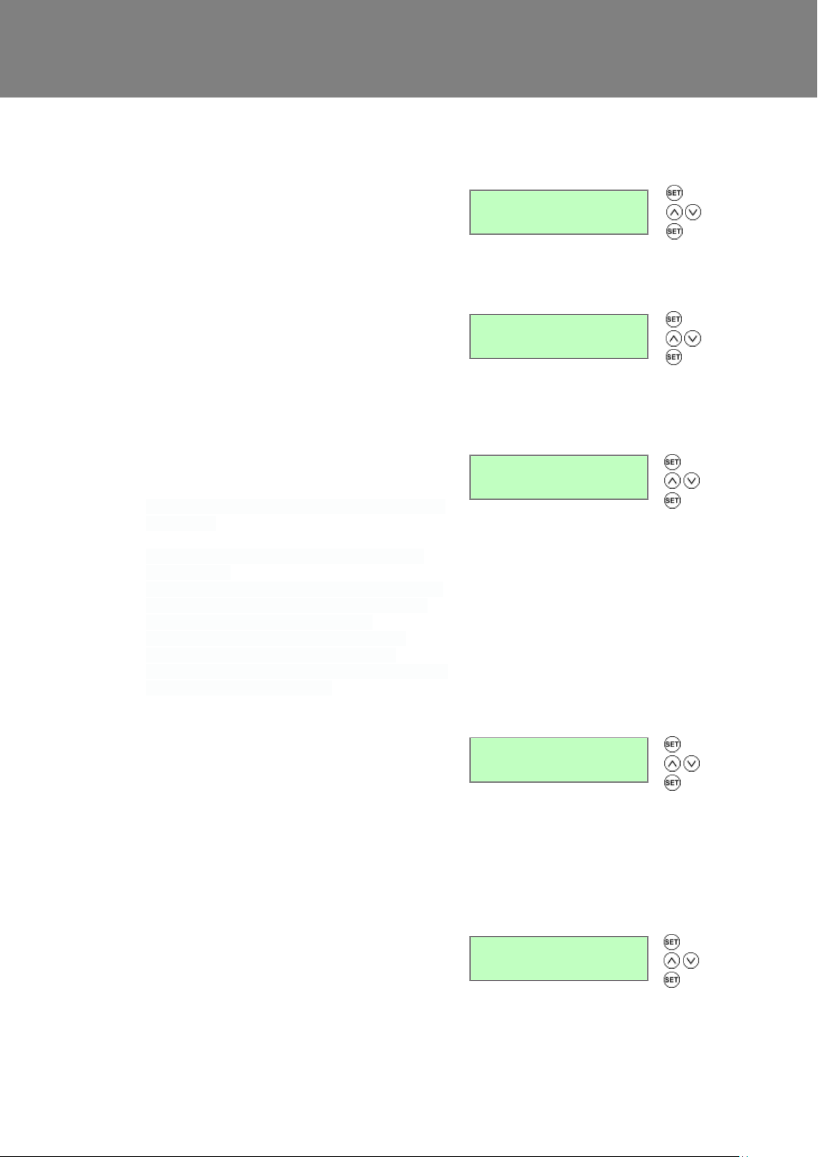
The Cooker Hood Supply screen enables you to set the
Boost speed for the Supply fan.
supply speed = 30%
Ckr Hood Supply
100 %
The Cooker Hood Extract screen enables you to set
the Boost speed for the Extract fan.
Default Cooker Hood speed = 100%
Cooker Hood extract speed cannot be set below Boost
speed.
Ckr Hood Extract
100 %
This feature delays the LS input boost operation for a
maximum of 20 minutes to reduce noise and cold
drafts while bathing.
With Comfort Mode enabled, activation of the LS boost
is as follows:
1. If the LS input is deactivated within 3 minutes no
boost will occur
2. If the LS input is deactivated between 3-20 minutes,
an LS boost will be triggered with duration of [Boost
Overrun] + [Time LS was active] minutes.
3. If the LS input is active for over [Boost Delay]
minutes, an LS boost will activate; when LS is
eventually deactivated, the boost will overrun for [Boost
Overrun] + [Boost Delay] minutes.
Comfort mode
on
The Boost Overrun screen enables you to set a time
period for the fans to boost airflow (in minutes) after the
light switch (LS input) is turned off. It will then return to
normal airflow.
Selectable range: minimum = 00, maximum = 30,
default = 15.
Boost Overrun screen does not function for inputs
S/W1 to S/W3 and SW4, SW5
Boost Overrun
15 m
The Boost Delay screen enables you to set the time
delay (in minutes) from the light switch (LS input) being
switched on to the airflow boost being activated. This is
used to prevent the unit from boosting unnecessarily
when the light switch is switched on for short periods.
Selectable range: min. = 00, max. = 10, default = 00.
Boost Delay
00 m
Cooker Hood Supply Screen
Cooker Hood Extract Screen
Comfort Mode
Boost Overrun Screen
Sentinel Kinetic MVHR Installation & Commissioning 32
Boost Delay Screen
Page 33
Commissioning
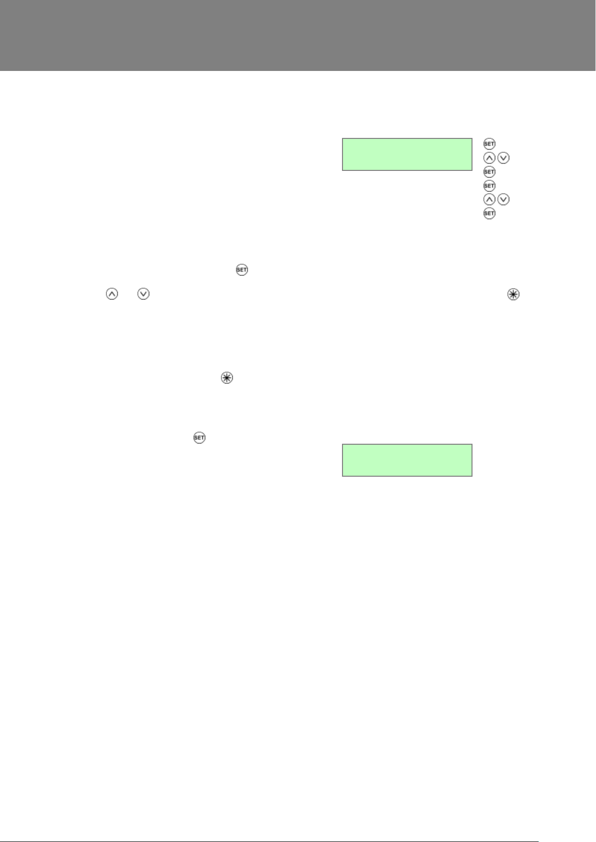
The Boost On/Off screen enables you to set a time for
boost to be activated for each day of the week.
You can set up to three On/Off times per day, shown
as Day1, Day2 and Day3. If On and Off times are the
same, the unit will not change speed.
On time cannot be set earlier than a previous off time,
Likewise, Off time cannot be set earlier than a previous
On time.
To set a weekly schedule:
Setting starts at Mon1 and uses to show, by
flashing, which item is available for adjustment with the
and buttons (a → b → c → d → e → Mon2 and
so on).
Mon1 10:01 11:11
↑ ↑ ↑ ↑ ↑
a b c d e
When Day flashes, pressing (> 2 sec) will copy
yesterday’s times to today.
Setting finishes when the last off minutes for Sun3 are
accepted, at which point the screen will now show
All Set or holding the button for 3 seconds.
Boost On Off
Mon1 00:00 00:00
Boost On Off
All Set
(Day)
(Day)
(On)
(On)
Repeat for Off
Repeat for each
Day.
Note: if same
times are used
on subsequent
days, will
copy times
found.
Boost On/Off Screen
Sentinel Kinetic MVHR Installation & Commissioning 33
Page 34
Commissioning
The Normal Airflow mode can be set to run during the
daytime i.e. from 6am to 11pm, the Low Airflow mode
will then run during the night from 11pm to 6pm.
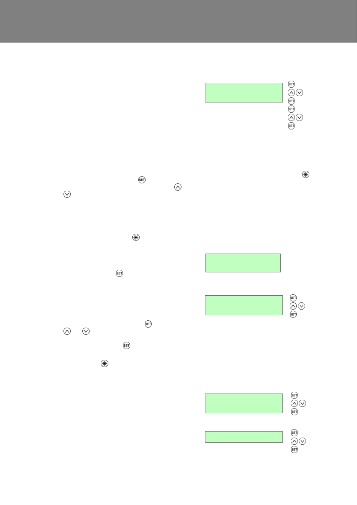
The Normal On/Off screen enables you to set a time for
Normal to be activated for each day of the week.
You can set up to one On/Off time per day, If On and
Off times are the same, the unit will not change speed.
On time cannot be set earlier than a previous off time,
Likewise, Off time cannot be set earlier than a previous
On time.
To set a weekly schedule:
Setting starts at Mon and uses to show, by flashing,
which item is available for adjustment with the and
buttons (a → b → c → d → e → Mon and so on).
Mon 10:01 11:11
↑ ↑ ↑ ↑ ↑
a b c d e
When Day flashes, pressing (> 2 sec) will copy
yesterday’s times to today.
Setting finishes when the last off minutes for Sun are
accepted, at which point the screen will now show
All Set or holding the button for 3 seconds.
Normal On Off
Mon 00:00 00:00
The Set Service No screen enables you to enter the
telephone number that should be called for service in
the event the unit fault.
Initially the screen is blank. Press to get a 0. Use
and buttons to change between 0 and 9 (or
blank). Repeat until the number is entered. Finally,
select a blank and press to finish. Maximum 16
digits.
Press and hold for more than 2 seconds to clear
service number.
Set Service No
The Humidity Sensor screen enables you to
switch the Sensor On and adjust the trigger point
between 50% and 90%. (default setting 70%).
Humidity Sensor
Off
The Sentinel kinetic does not just look for relative
humidity levels above a set point, which can be
unreliable in products that extract from multiple rooms,
but it also looks for rapid increase in relative humidity
typically generated by such activities as showering or
cooking. This feature allows an overrun of up to 60
minutes from a “Rapid rise” of humidity.
RH RR Overrun
(Day)
(Day)
(On)
(On)
Repeat for Off
Repeat for each
Day.
Note: if same
times are used
on subsequent
days, will
copy times
found.
Normal on off
All Set
Humidity Rapid-Rise (RH RR) Overrun
Normal On/Off Screen
Set Service No Screen
Internal Humidity Sensor Screen (if fitted)
Sentinel Kinetic MVHR Installation & Commissioning 34
Page 35
Commissioning
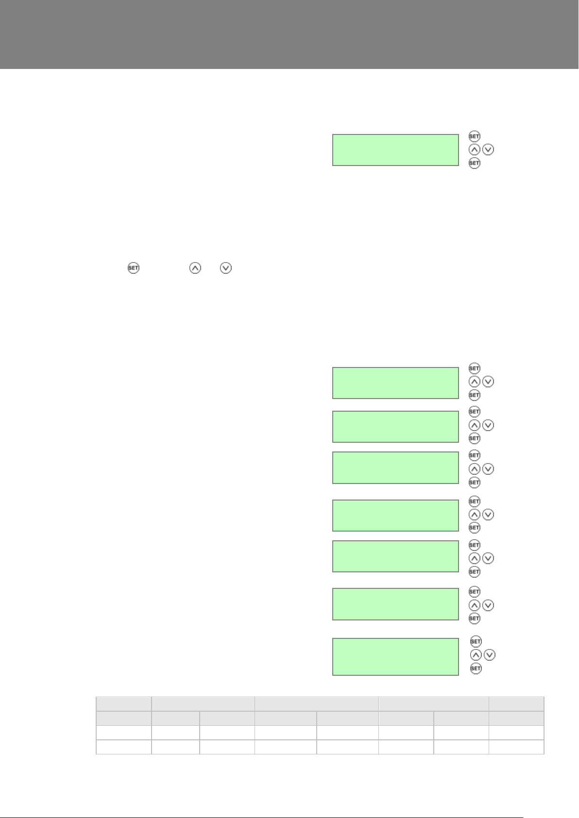
The Proportional 1 screen enables the conditions of the
proportional sensors to be set.
The unit can receive a 0-10 V proportional signal from
either a humidity, CO2 or temperature external sensor,
when connected to terminals P1.
By default, the Proportion 1 input is set for a humidity
sensor operation.
When you have selected the sensor type, screens for
the appropriate boost and normal limits are displayed.
Press and use the and buttons to change the
selection (Humidity-default, CO2, Temperature, Pure
0-10V).
When the input signal is below the ‘Normal Limit’, the
unit runs at low / normal airflow. When the signal is
above the ‘Boost Limit’, the unit runs at boost airflow.
Between these limits the unit runs at a proportional
airflow.
Proportional 1
Humidity
For a humidity sensor, a percentage value must be
entered for boost and normal settings. For range and
default values, see Table 2 below.
P1 Boost Limit
70 %
P1 Normal Limit
60 %
For a CO2 sensor, a figure (in ppm) must be entered for
boost and normal settings. For range and default
values, see Table 2 below.
P1 Boost Limit
2000 ppm
P1 Normal Limit
1000 ppm
For a Temperature sensor, a figure (in degrees C) must
be entered for boost and normal settings. For range
and default values, see Table 2 below.
P1 Boost Limit
27 C
P1 Normal Limit
17 C
For a pure 0V to 10V input, anything below 0.1V will be
no proportional boost, >9.9V for full boost
Pure 0-10V
Sensor
Humidity
CO2
Temperature
Pure 0-10V
Default (%)
Range (%)
Default (ppm)
Range (ppm)
Default (°C)
Range (°C)
Range (V)
Boost limit
70
25-90
2000
200-2000
27
10-35
9.9
Normal limit
60
25-90
1000
200-2000
17
10-35
0.1
Proportional 1 Screen
Sentinel Kinetic MVHR Installation & Commissioning 35
Table 2: Boost & Normal Limits – Defaults and Adjustment Range
Page 36
Commissioning
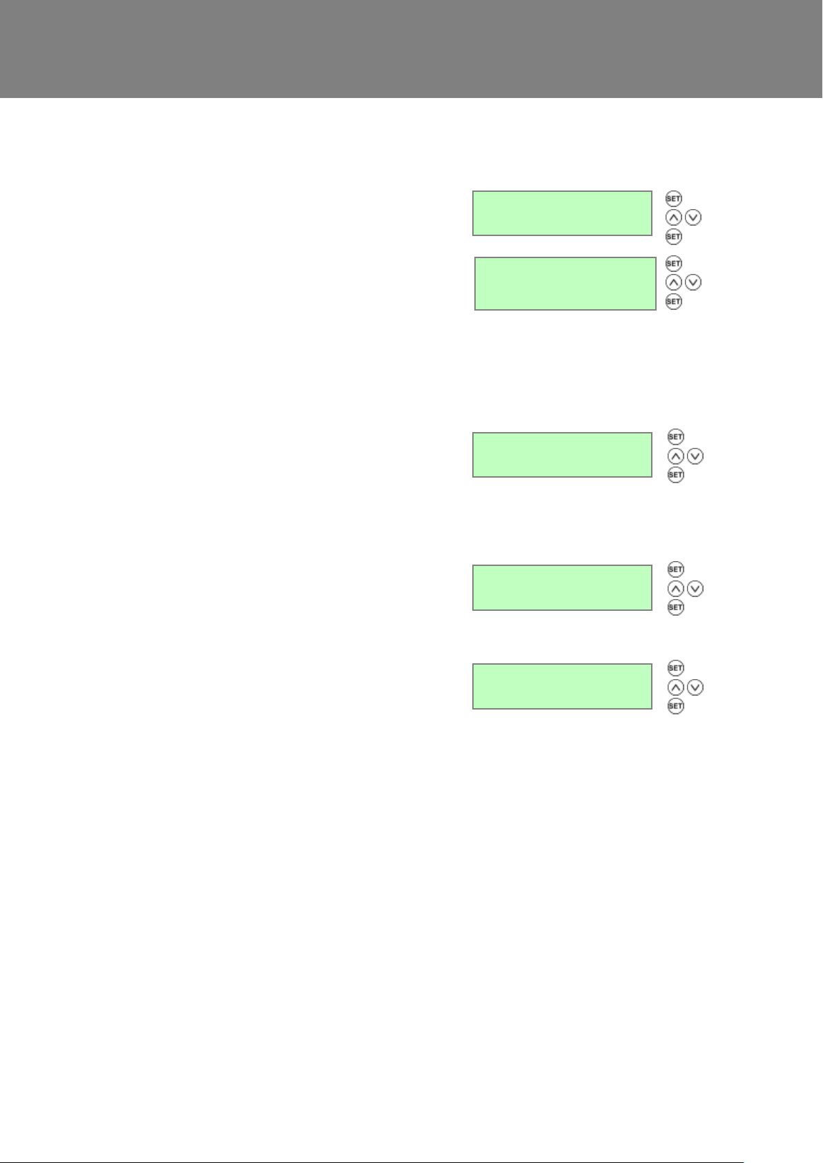
By default, the Proportional 2 input is set to CO2 sensor
operation.
See Proportion 1 Screen for a description.
Proportional 2
CO2
To select between boost or low flow
Default = Boost
SW5 Flow
The Boost Button screen allows the boost button on the
front of the unit and on a remote control, if fitted, to be
disabled by setting to Off. When set to Off this also
disables the Purge function.
Available options = On (default) and Off.
Boost Button
On
This screen by default displays CV mode. The unit can
operate by choosing Constant Volume or Constant Pressure,
or can be set to Off to run on fan curve. Default for standard
unit is Off and for CVP unit is CV.
CVP Control
Off
The Summer Bypass screen is factory set if one has
been fitted. It will only need resetting if a replacement
control board has been fitted.
Available options = Not fitted (default) and Fitted.
Summer Bypass
Not Fitted
SW5 Screen
Proportional 2 Screen
Boost Button
CVP Control (Currently unavailable option)
Summer Bypass Screen
Sentinel Kinetic MVHR Installation & Commissioning 36
Page 37
Commissioning
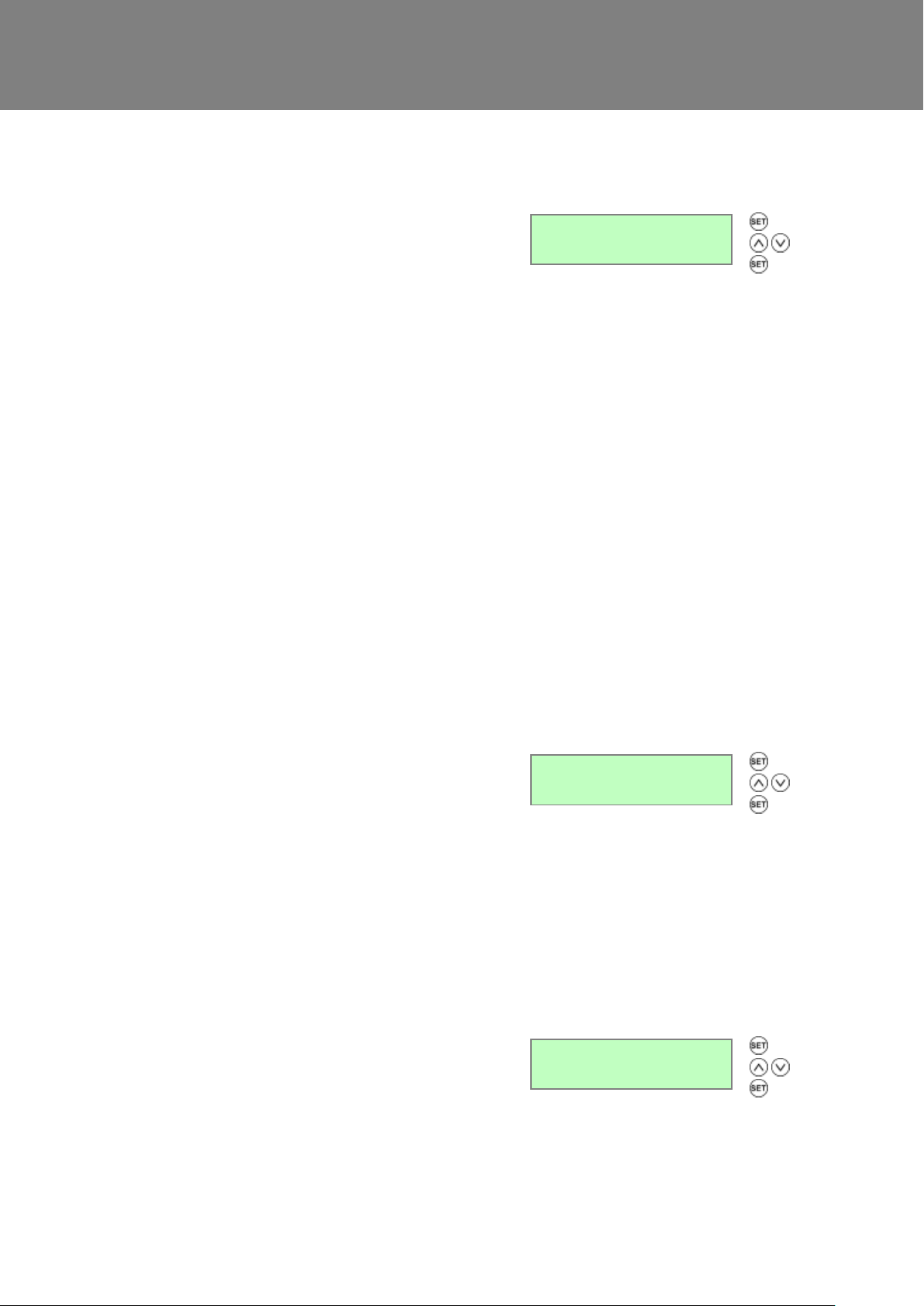
The Antifrost screen is only displayed if a summer
bypass is fitted. In installations where a negative
pressure is not permitted such as where an open flue
fireplace or appliance is fitted, set this to bypass mode.
Standard available options are Airflow Mode (default)
and Bypass Mode.
An additional option is Anti Frost with Heater Mode
which should be selected if a pre heater is fitted. See
the next screen, below. (Currently unavailable option).
Airflow Mode - When the supply air temperature is
between 0° and -20°C, antifrost will automatically
activate. This will reduce the supply airflow rate and
increase the extract airflow rate to prevent frost forming
on the heat exchanger. During antifrost operation the
supply motor can stop for 15 minutes per hour and run
for 45, depending on the temperature below 0°C. If the
supply air temperature is -20°C or below the supply fan
switches off and the extract fan continues to run at
reduced rate to prevent frost forming on the heat
exchanger.
Bypass Mode - While the supply air temperature is
below 0°C, the antifrost mode will automatically
activate. This mode will open the bypass to prevent
frost forming on the heat exchanger.
Antifrost
Airflow Mode
If an electrical pre heater is being used in conjunction
with the anti-frost system to prevent freezing of the
heat recovery cell then this is set to On. The pre
heater control must be wired up according to its
instructions. See Appendix 2, options and
Accessories, 407198, Anti-Frost Heater Controller.
Otherwise leave set to Off.
Note that if any sensor or other input requires the
supply fan to stop, then the heater is switched off first
and the supply fan runs on for 60 seconds before it is
switched off in order to ensure that the heater is
cooled.
Available options: Off (default) and On.
Pre Heater
Off
The Dryout screen enables the fans to be run at max
speed for a week before returning to normal operation.
This feature can help to dry out fresh plaster and paint
enabling building work to be completed more quickly.
Filters may become fouled during this time and should
be cleaned or replaced afterwards.
Available options: Off (default) and On.
Dryout
Off
Antifrost Screen
Pre Heater Screen (Currently unavailable option)
Sentinel Kinetic MVHR Installation & Commissioning 37
Dryout Screen
Page 38
Commissioning
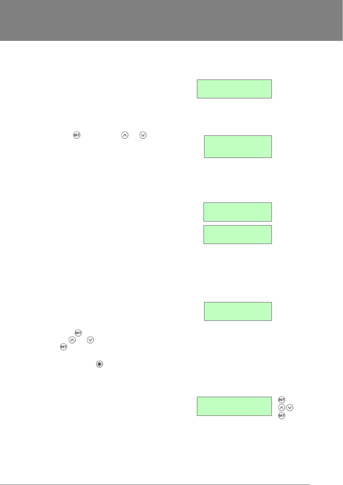
The Running Time screen displays the total running
time of the unit (in hours).
No changes may be made to this screen. In the event of
power failure total time will be retained.
Running Time
12345
Press and then use the and push-buttons to
select the time between Filter Services. The options are
Urban (6 months), Suburban (default: 12 months) or Rural
(18 months).
Filter Service
Suburban
On for BMS (default) or Off for Wired Remote Control,
automatically set up by BMS signal or Wired Remote
Control when either is plugged into BMS socket.
BMS Mode
On
The BMS screen displays byte count and first 16 bytes
from the Building Management System (BMS) system. The
output may controlled by a BMS system to switch the unit
on or off for example in conjunction with a smoke alarm.
No changes may be made to this screen.
BMS 00
The Security PIN screen enables you top set a four-digit
personal identification number (PIN) to access the
commissioning screens. This screen will show blank if
security is disabled and no PIN is used.
Press to reveal 0000 with the first 0 flashing and use
the and buttons to change the selection (0-9). Press
again to accept the digit and move to the next. Repeat
until all four digits are specified.
Press and hold for more than 2 seconds to clear
security PIN.
Security PIN?
The Restore Defaults screen enables you to restore the
default settings for all screens.
Available options: No (default) and Yes.
The default commissioning settings are present when
the unit is switched on and can be restored by setting
the Restore Defaults screen to Yes
Restore Defaults
No
Running Time Screen
Filter Service
B
B
B
BMS screen
Security PIN Screen
R
e
s
t
o
Restore Defaults Screen
Sentinel Kinetic MVHR Installation & Commissioning 38
Page 39
Commissioning
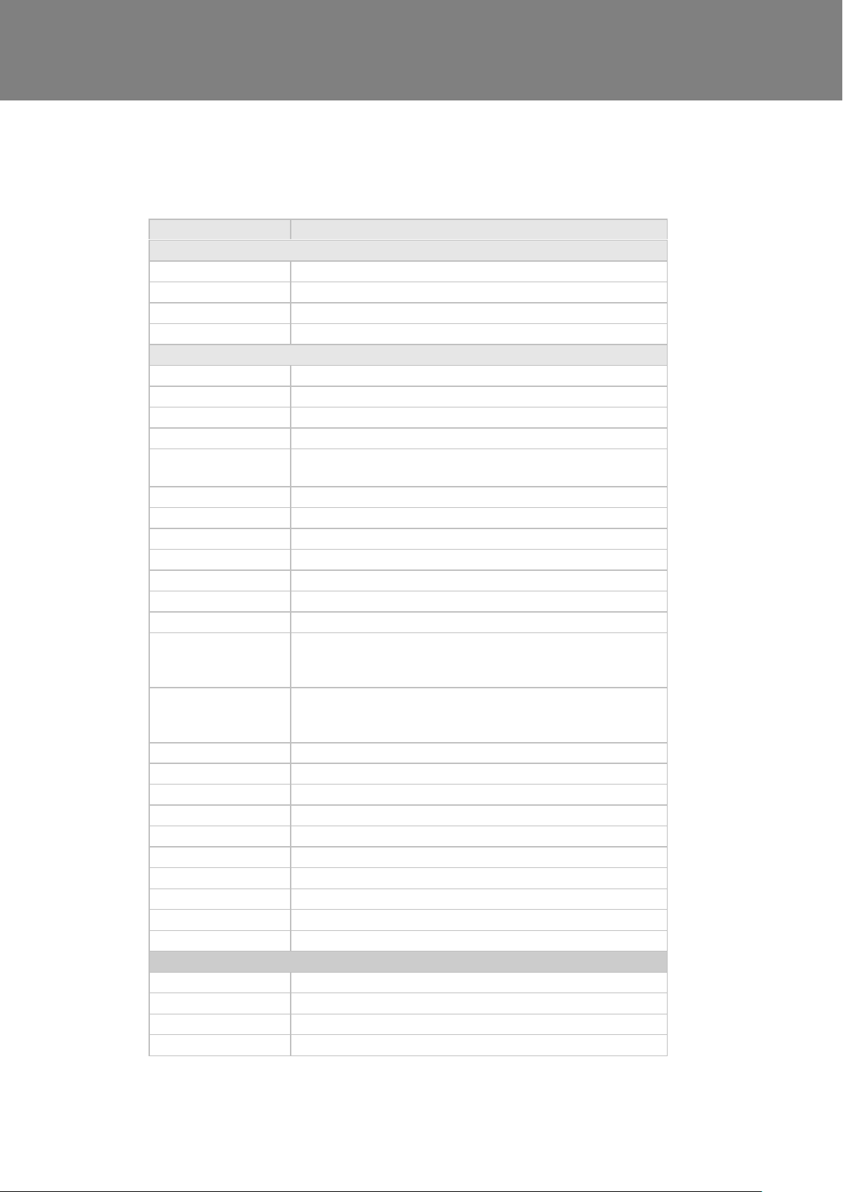
Parameters
Settings
Start-up Screens
Sentinel Kinetic
Sentinel Kinetic
Language
English.
Control Mode
01
Airflow Units
%.
Commissioning Screens
Security PIN
Not set
Boost Supply/Extract
50 %
Normal Supply/ Extract
30 %
Low Supply/Extract
20%
Cooker Hood
supply / extract
30% / 100%
Comfort Mode
off
Boost Overrun
15
Boost Delay
00
Boost On/Off
All days set to 0:00 (on), 00:00 (off) – inactive
Normal On Off
All days set to 0:00 (on). 00:00 (off) – inactive
Set Service No
Not set
Humidity
70%
Proportional 1
Humidity – Boost, Normal (60 %)
CO2 – Boost (2000 ppm), Normal (1000 ppm)
Temperature – Boost (27 C, Normal (17 C)
Proportional 2
CO2 – Boost (2000 ppm), Normal (1000 ppm)
Temperature – Boost (27 C, Normal (17 C)
Humidity – Boost, Normal (60 %)
SW4
Off
SW5
Boost
Boost Button
On
Summer Bypass
Not Fitted
Antifrost
Airflow Mode
Dryout
Off
Running Time
-
Filter Service
Suburban (default) 12 months, or can be set to Urban and Rural
BMS
On
Restore Defaults
Off
User Screens
Set Clock
-
Summer Bypass
Summer Bypass On
Indoor Temp
25 C
Outdoor Temp
14 C
Table 3: Default Settings
Sentinel Kinetic MVHR Installation & Commissioning 39
Page 40
Maintenance
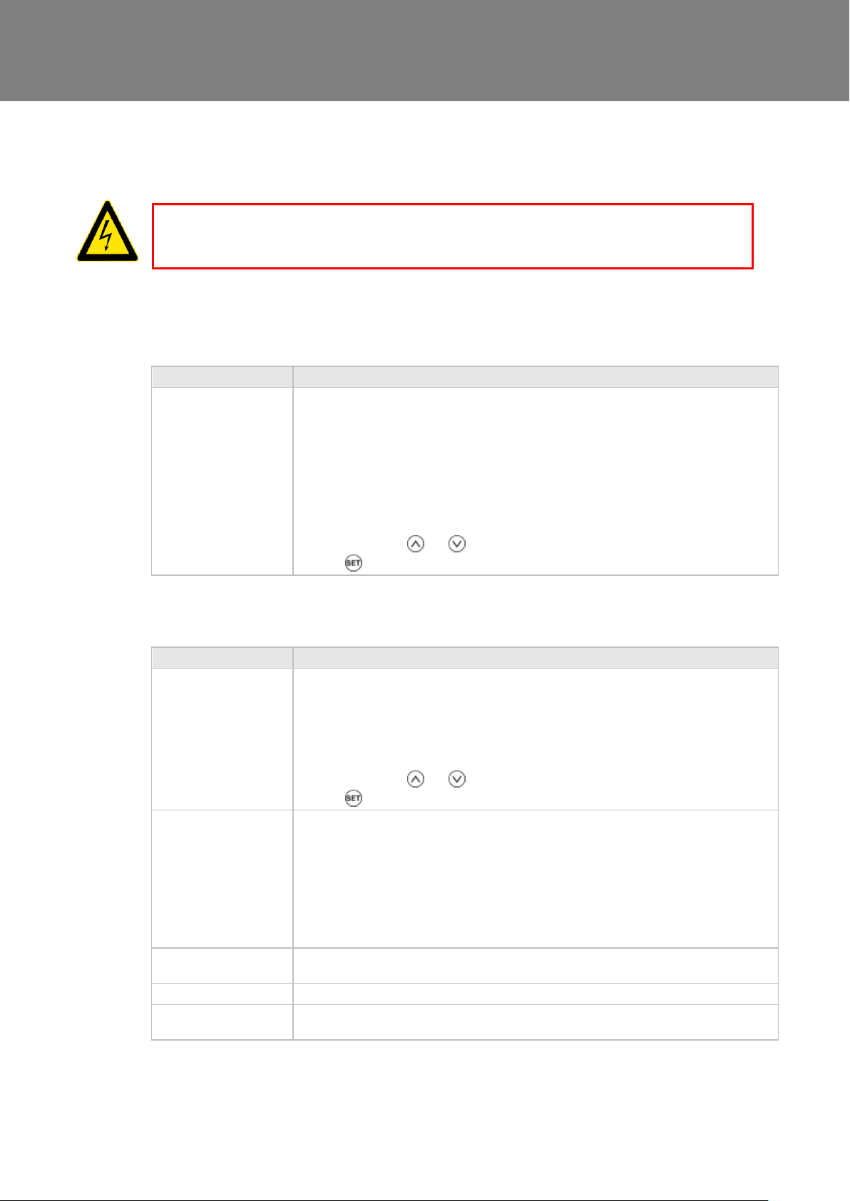
Item
Action
Fan Filters
When the unit displays “Check filters”. This is a reminder to ensure that the filters are not so
dirty that they are blocking the airflow or allowing dirt to pass through. The rate at which the
filters become dirty will vary hugely depending on the environment and the activity within the
property.
1. Open the filter flaps and remove the 2 filters.
2. Clean gently by tapping or carefully using a vacuum cleaner if necessary.
3. Replace the filters
4. Close the filter flaps.
5. To Reset the filter service time:i) press and hold the and buttons for 5 seconds until “Reset Filter?” is shown.
ii) Press to confirm reset “Filter Reset” will be shown.
Item
Action
Fan Filters
(Interval to suit
environment)
Change the Fan Filters depending on which environment the unit has been installed; urban,
suburban or rural.
1. Open the filter flaps and remove the 2 filters.
2. Insert the replacement filters.
3. Close the filter flaps.
4. To Reset the filter service time:i) press and hold the and buttons for 5 seconds until “Reset Filter?” is shown.
ii) Press to confirm reset “Filter Reset” will be shown.
Unit & Heat Exchanger
Cell
Inspect and clean the unit
1. Isolate the mains power supply.
2. Remove front cover from the unit.
3. Remove the 2 filters.
4. Slide out the heat exchanger.
5. Wash the outer cover and heat exchanger in warm water using a mild detergent and dry
thoroughly.
NOTE: Keep water away from all electrical components and wiring within the unit.
Motors
Inspect the motors for build-up of dust and dirt on the impeller blades, which could cause
imbalance and increased noise levels. Vacuum or clean if necessary.
Condensate Drain
Check the condensate drain tube is secure and clear of debris. Clean if necessary.
Fastenings
Check that all unit and wall-mount fastenings are sufficiently tight and have not become
loose. Re-tighten if necessary.
Maintenance
Heat recovery units, by their very nature, require regular maintenance. The Sentinel Kinetic has been designed
to facilitate access to enable maintenance to be carried out easily.
THE FAN AND ANCILLARY CONTROL EQUIPMENT MUST BE ISOLATED FROM THE POWER SUPPLY
Filter Maintenance
WARNING
DURING MAINTENANCE.
Periodic Maintenance
Sentinel Kinetic MVHR Installation & Commissioning 40
Page 41

Maintenance
Part No
Description
497808
Control PCBA & Patch Cable Kit
497814
Sensor Leads & Patch Cable Kit
SENTINEL KINETIC B/BH SPARES
442356
G3 Filters, 2 per pack (438222 & 438242)
444199
M5 Single Filter (438222 & 438242)
441764
Heat Recovery Cell (bypass version 438222)
441996
Heat Recovery Cell (non-bypass version 438242)
497812
Supply Motor & Cable Kit
497810
Extract Motor & Cable Kit
441776
Summer Bypass
438378
Spigot, one per pack
SENTINEL KINETIC F SPARES
409764
G3 Filters, 2 per pack
472153
M5 Single Filter
409766
Heat Recovery Cell
497816
Motor Assembly & Patch Cable Kit
409772
Summer Bypass
409774
Spigot, one per pack
SENTINEL KINETIC PLUS SPARES
403702
G3 Filters, 2 per pack
444201
M5 Single Filter
443352
Heat Recovery Cell
497818
Motor Assembly & Patch Cable Kit
443355
Summer Bypass
444057
Spigot diameter 150 mm, one per pack
446523
Spigot diameter 180 mm, one per pack, complete with foam adaptor to make 200mm spigot.
SENTINEL KINETIC HIGH FLOW SPARES
403702
G3 Filters, 2 per pack
444201
M5 Single Filter
443352
Heat Recovery Cell
497820
Motor Assembly & Patch Cable Kit
443355
Summer Bypass
446523
Spigot diameter 180 mm, one per pack, complete with foam adaptor to make 200mm spigot.
Spares
The following spares may be ordered from Vent-Axia:
Sentinel Kinetic MVHR Installation & Commissioning 41
Page 42
Troubleshooting
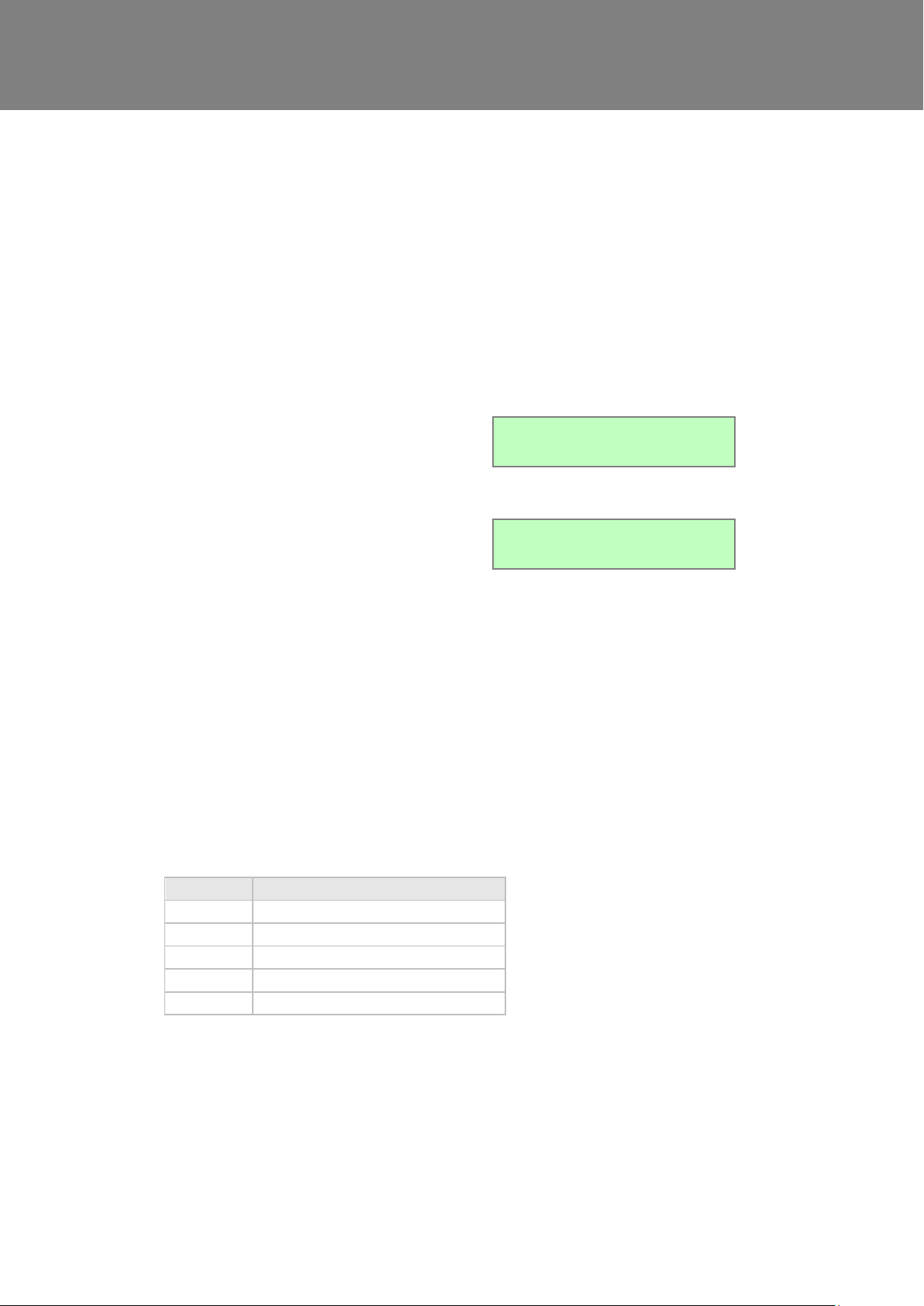
The Service screen is displayed, alternating with
the Fault Code screen, when a fault has caused
the unit to switch off and you must phone the
telephone number displayed on the screen for
assistance.
Service Phone
01293nnnnnn
The Fault Code screen is displayed, alternating
with the Service screen, when a fault has
occurred. Take note of the fault code when
reporting a fault.
Fault Code
01
Code
Problem
01
Supply Fan not running
02
Extract Fan not running
08
Temperature sensor T1 (supply) faulty
16
Temperature sensor T2 (extract) faulty
32
Wired Remote Control failure
Troubleshooting
Diagnosing a Problem
In the event of a problem, always troubleshoot the unit according to:
Fault code displayed on the Control Unit.
Fault LED if connected.
If no indications are displayed, then troubleshoot problem according to the fault symptom as described in the
following tables.
Service/Fault Code Screens
For assistance contact the service provider and quote the fault code number.
Note that the fault code is not displayed until the fault has been present for 3 minutes.
The following fault codes numbers may be displayed.
Code numbers are added together if more than one fault is detected.
For example: Code 03 indicates that both supply and extract fans are not running.
Table 4: Fault Codes
Sentinel Kinetic MVHR Installation & Commissioning 42
Page 43

Troubleshooting
The Room Too Cold screen displays the status of the
fan. If the heating system in the building fails or is
switched off and the internal temperature drops below
5°C, the unit will stop running so as to not bring cold air
into an already cold house. The unit will start up every
hour and will run for a short time to measure the
temperature of the property. When the temperature
rises, e.g. the heating system is switched back on, the
unit will restart and continue normal operation.
Bottom line of display may be (Fan Off, Fan
Restarting).
Room Too Cold
Fan Off
Room Too Cold Screen
Note: Access to the commissioning screens is prevented if the display shows Antifrost Active, Room
Too Cold or a Fault Code. In this event, switch the unit off and on again and enter the commissioning
screens within one minute. If you are within the commissioning screens the Antifrost and Room Too
Cold Failures modes will not operate allowing the flow rates to be adjusted even in a property which is
below 5C.
Sentinel Kinetic MVHR Installation & Commissioning 43
Page 44
Appendix One
Terminal No.
Name
Description (Control Mode 02)
S/W1
Switch 1
With link fitted to J4 – Volt- free switch – Low Mode
S/W2
Switch 2
With link fitted to J4 – Volt- free switch – Normal Mode
S/W3
Switch 3
With link fitted to J4 – Volt- free switch – Boost Mode
S/W4
Switch 4
Volt-free contact for sensor input between + and – terminals
(Momentary if SW/4 if SW4 Commissioning Screen set On)
S/W5
Switch 5
Fire System or SW/5 open Stop
P1 0-10V
Proportional 1
A 24 V DC sensor supply is output between the + and - terminals.
A 10 V proportional sensor input is received between S and - terminals
P2 0-10V
Proportional 2
A 24 V DC sensor supply is output between the + and - terminals.
A 10 V proportional sensor input is received between S and - terminals
LED
Red Light Emitting Diode
Output
A LED driving signal output between the + and – terminals that enables
remote indication of a unit fault. See the Control Panel for fault code
(see Service/Fault Code Screens on page 42).
L
Mains Live
220-240 V AC, 50 Hz input
N
Mains Neutral
220-240 V AC, 50 Hz input
EARTH
Mains Earth
Earthing connector
LS
Switched Live
220-240 V AC, 50 Hz input
Connection
on Rear
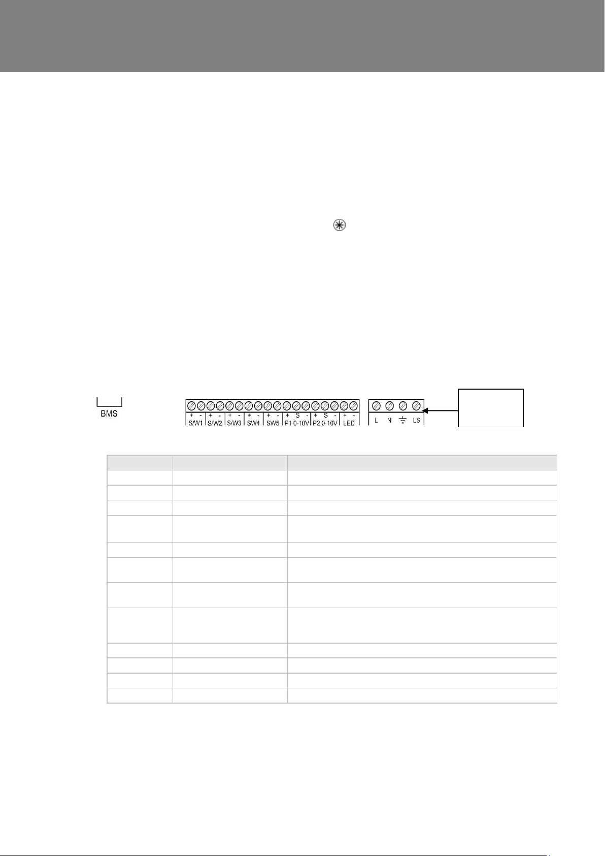
Appendix One: Control Mode 02 Description
Overview
The functional differences described in this Appendix are available when Control Mode 02 is selected from the
start-up screens. Control Mode 02 assigns alternative functions to certain wiring Terminal Connections and
allows additional airflow settings to be accessed via the button on the front of the Kinetic unit or remote
control.
N.B.1. If control mode 02 is selected then SW5 must have a link connecting the +
and – terminals or a normally closed device such as a fire system.
N.B.2. Accessories will not function if Control Mode 2 is selected.
Terminal Connections and Functions
The following switching Functions are available with Control Mode 02:
Sentinel Kinetic MVHR Installation & Commissioning 44
Page 45
Appendix One
No. of presses
Airflow Mode
(Control Mode 02)
1
Low
2
Normal
3
Boosts 30 minutes
4
Boosts 60 minutes
5
Boosts continuously
6
Cancel
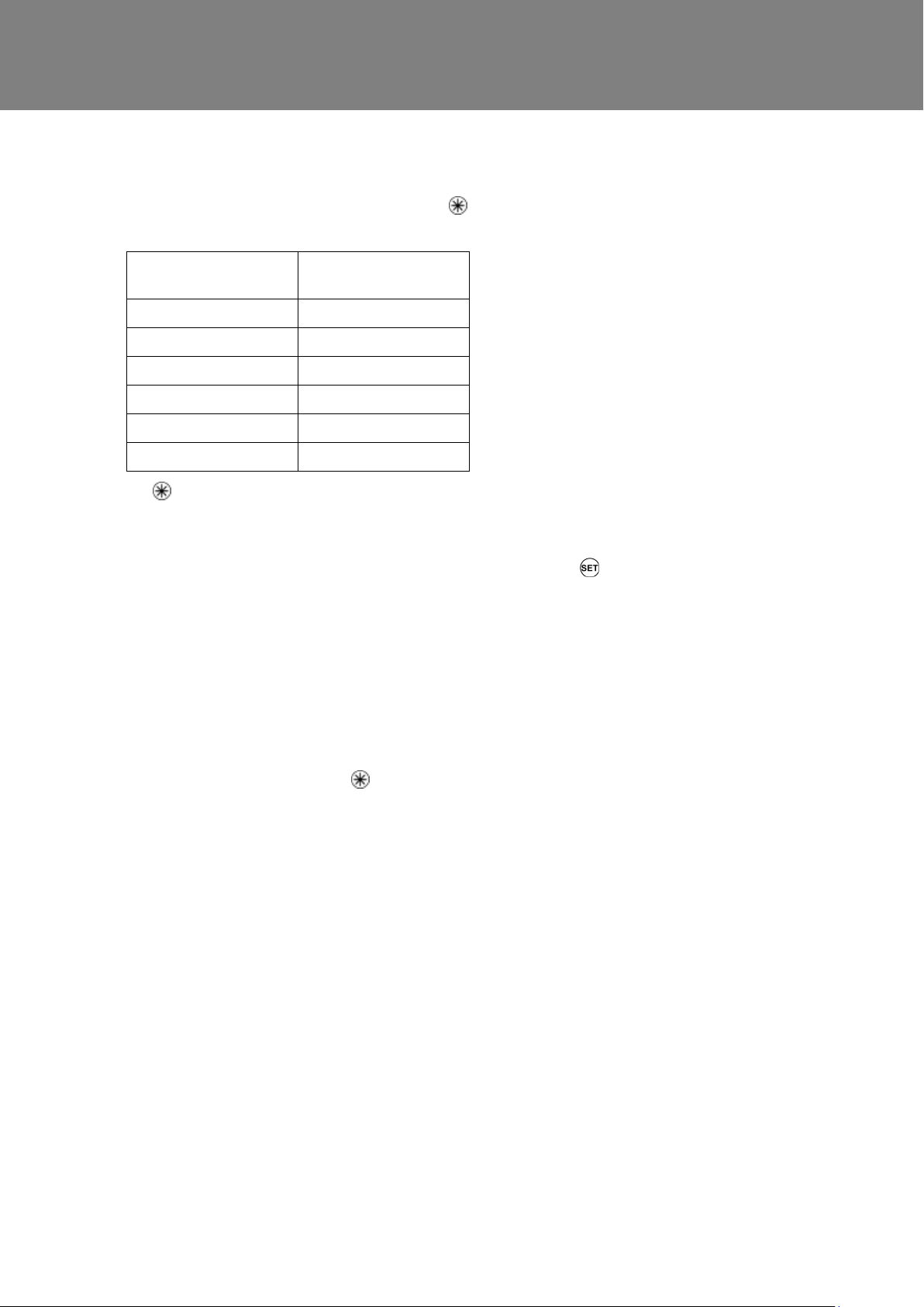
Airflow Mode Selection
The following switching Functions are available via the button with Control Mode 02:
Press 10 seconds after last press to cancel and return to normal operation.
If the wireless boost option is fitted, this can be triggered from the wireless transmitter/boost switch.
If the installation has switch sensors, is wired to the lighting, or if the internal time switch is set for periodic operation,
then operation will change from normal to boost automatically. Pressing the
device has activated boost.
s4 = Switch SW4
v1 = S/W1
v2 = S/W2
v3 = S/W3
ls = Switched live (LS)
c1-3 = Internal Time switch
If running on boost due to pressing the button, another device may ‘take over’ the boost. Flow will return to normal
when that device switches off. If a number of different devices are calling for boost flow, the unit will run at boost until the
last one has reverted to normal.
button will reveal a code to show which
Sentinel Kinetic MVHR Installation & Commissioning 45
Page 46

Appendix Two
1. Remove a blind grommet from the Cable Inlet plate
and insert the 3 core cable from Cooker hood.
2. Connect the 3 wires to the terminal block
marked J12
Brown = L
Grey = N
Black = LS
Appendix Two: Options and Accessories
CO2 Sensor
An optional wall-mounted CO2 Sensor (433257) may be used to control airflow. The CO2 sensor measures the
CO2 level in ppm (parts per million) and the unit adjusts the fan speed accordingly. When the CO2 level is below
the lower threshold (adjustable), the fan will run at Normal speed. When the CO2 level is above the upper
threshold (also adjustable), the fan will run at Boost speed. If the CO2 level is between the lower and upper
thresholds, the fan will run at a speed between Normal and Boost proportional to the difference between the
CO2 level and the thresholds.
Normal / Boost Switch
An optional Normal/Boost Switch (455213) may be used to control airflow. Connecting a switch will enable a
manual control to be used in conjunction with other boost controls.
Humidistats
An internal Relative Humidity Sensor PCB (495976) may be used to control airflow. The unit adjusts the fan
speed proportionally depending on the temperature and relative humidity levels in the extracted air whilst
avoiding nuisance tripping at night time when temperatures drop and relative humidity naturally rises. The unit
does not just look for relative humidity levels above a set point, which can be unreliable in products that extract
from multiple rooms, but it also looks for rapid increase in relative humidity typically generated by such activities
as showering or cooking.
Connecting a System Cooker Hood
A system cooker hood that has a Switched Live output to trigger the unit from normal to cooker hood boost can
be connected as follows. The cooker hood must be double insulated.
Connecting an Opto-coupler (447340)
The LED terminals are intended to drive a remote LED to indicate that a fault has occurred. They provide a
LED driving signal output between the + and – terminals that enables remote indication of a unit fault. See the
Control Panel for fault code (Refer to installation and commissioning guide listed above). This signal could also
be used by a BMS system so that it is informed that a fault has occurred. If a volt-free contact is required then
Sentinel Kinetic MVHR Installation & Commissioning 46
use this opto-coupler to provide electrical separation.
Connect the flying leads of the opto-coupler pcb into the LED terminals, + to + and - to -
Connect the pair of leads from the BMS to the terminal block of the opto-coupler pcb.
Page 47
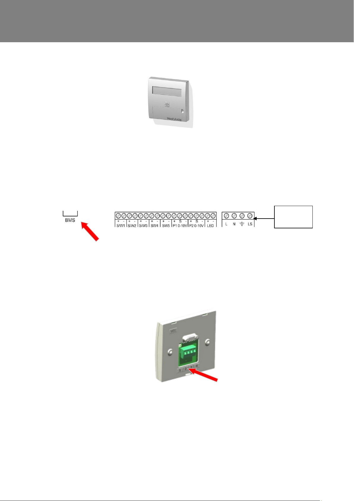
Appendix Two
Connection
on Rear
Wired Remote Control (443283)
1. The Wired Remote Control uses 15 metre long cable and has the same functionality as the control mounted
on the unit, it can be permanently mounted in a living space for the end user or used for commissioning the
unit.
2. To fit the Wired Remote Control remove the Front, Rear and Electrical covers, using the cable assembly
supplied insert the plug into the socket marked BMS and feed the remaining cable through cable inlet
plate, refit all covers.
3. Connect the cable assembly (4 wires numbered 1 to 4) to the Remote Control terminal block and mount onto
a single gang recessed wall box with the 2 screws provided. The Wired Remote Control will automatically be
detected.
Sentinel Kinetic MVHR Installation & Commissioning 47
Isolator Relay Controller (442030)
The isolating relay controller allows several LS signals to be combined from independent circuits. For instance,
from lighting circuits on different floor levels.
Page 48
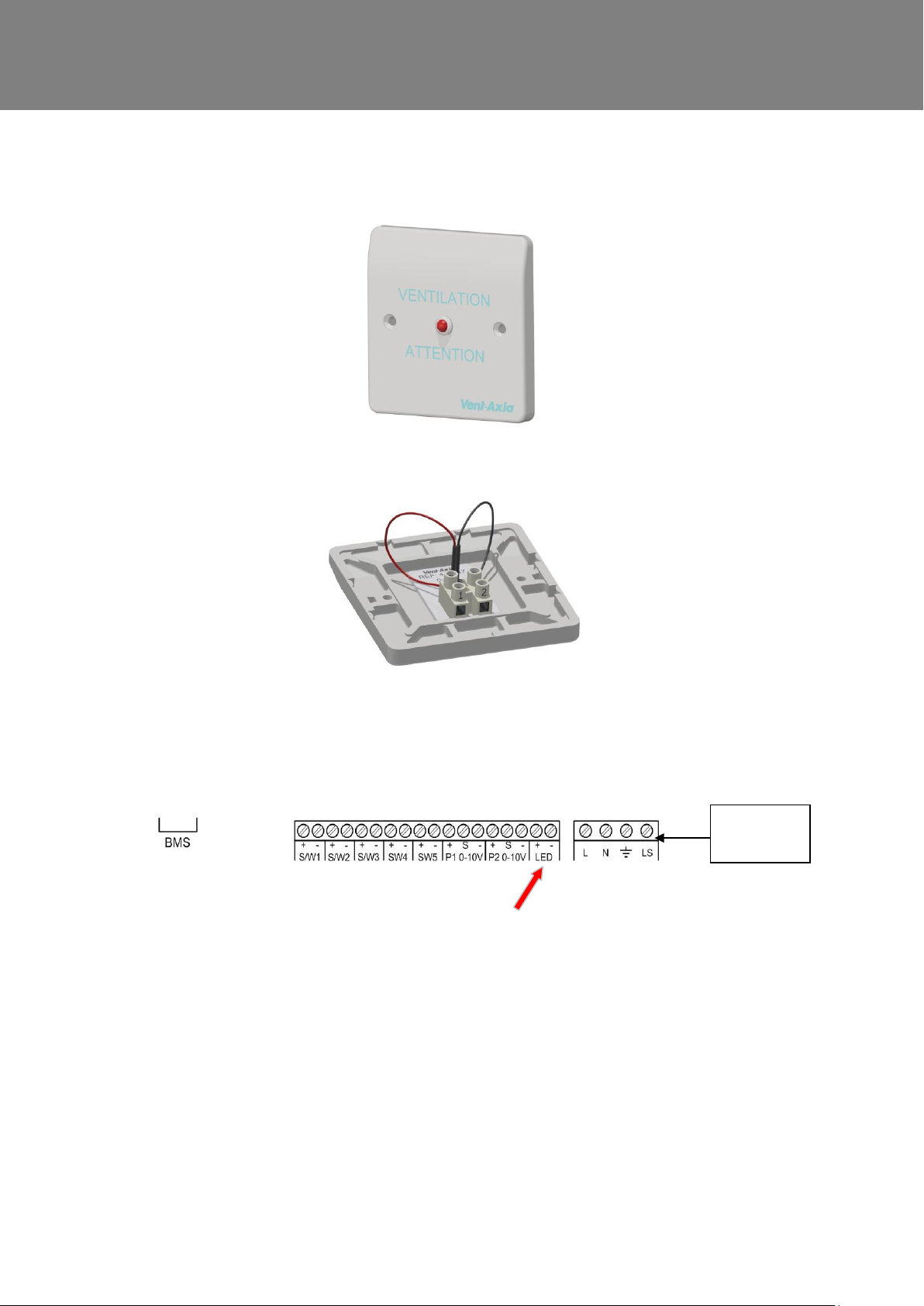
Appendix Two
Connection
on Rear
Remote LED Indicator (448347)
The LED terminals are intended to drive a remote LED to indicate that there is a message in the control display.
They provide a LED driving signal output between the + and – terminals that enables remote indication of filter
check or unit fault. See the Control Panel for message (See page 45 for fault codes).
Connect the 2 core flying lead from the Remote LED indicator terminal block. Terminal 1 on the Remote LED is +
and terminal 2 is -
Connect the other end of the lead to the LED + &- terminals on the Kinetic unit PCB. Please ensure that the +
goes to + and the – goes to -.
Sentinel Kinetic MVHR Installation & Commissioning 48
Page 49

Page 50

Appendix Three
Name:
Vent-Axia
Vent-Axia
Vent-Axia
Model ID (Stock Ref.) :
Kinetic B / L - 438222/
L
Kinetic BH /L-
443319/ L
Kinetic Plus B -
443028/L
SEC Class A A
A+
SEC Value ('Average')
-41.41
-41.41
-43.81
SEC Value ('Warm')
-16.49
-16.49
-18.55
SEC Value ('Cold')
-85.69
-85.69
-88.70
Label Required? (Yes/No=Out of scope)
Yes
Yes
Yes
Declared as: RVU or NRVU/UVU or BVU
RVU/BVU
RVU/BVU
RVU/BVU
Speed Drive
Variable Speed
Variable Speed
Variable Speed
Type HRS (Recuperative, Regenerative, None)
Recuperative
Recuperative
Recuperative
Thermal Eff: [ (%), NA(if none)]
87.00
87.00
90.00
Max. Flow Rate (m3/h)
237.60
237.60
432.00
Max. Power Input (W): (@Max.Flow Rate)
128.00
128.00
173.00
LWA: Sound Power Level (dB)
52.13
52.13
52.23
Ref. Flow Rate (m3/s)
0.04620
0.04620
0.08400
Ref. Pressure Diff. (Pa)
50.00
50.00
50.00
SPI [W/(m3/h)]
0.34
0.34
0.20
Control Factor & Control Typology: (CTRL/ Typology)
Control Factor; CTRL
0.65
0.65
0.65
Control Typology
Local Demand Control
Local Demand
Control
Local Demand
Control
Declared: -Max Internal & External Leakage Rates(%) for BVUs or carry
over (for regenerative heat exchangers only),
-&Ext. Leakage Rates (%) for Ducted UVUs;
<5% Internal, <5%
External
<5% Internal, <5%
External
<5% Internal, <5%
External
Mixing Rate of Non-Ducted BVUs not intended to be equipped with one
duct connection on either supply or extract air side;
N/A
N/A
N/A
Position and description of visual filter warning for RVUs intended for
use with filters, including text pointing out the importance of regular
filter changes for performance and energy efficiency of the unit
Refer to User
Instructions
Refer to User
Instructions
Refer to User
Instructions
For UVUs (Instructions Install Regulated Supply/Extract Grilles Façade)
N/A
N/A
N/A
Internet Address (for Disassembly Instructions)
www.vent-axia.com
www.vent-axia.com
www.vent-axia.com
Sensitivity p. Variation@+20/-20 Pa: (for Non-Ducted VUs)
N./A
N./A
N./A
Air Tightness-ID/OD-(m3/h) (for Non-Ducted VUs)
N./A
N./A
N./A
Annual Electricity Consumption: AEC (kWh/a) Per. 100m²
2.23
2.23
1.52
Annual Heating Saved: AHS (kWh/a) Per. 100m²
AHS: Average
46.31
46.31
46.93
AHS: Warm
20.94
20.94
21.22
AHS: Cold
90.60
90.60
91.82
For Residential Ventilation Units (Complying Commission Delegated Regulation (EU) No 1254/2014)
PRODUCT FICHE
Page 51

Appendix Three
Name:
Vent-Axia
Model ID (Stock Ref.) :
Kinetic High Flow / L - 408449 / 408451
SEC Class
A
SEC Value ('Average')
-40.98
SEC Value ('Warm')
-15.72
SEC Value ('Cold')
-85.86
Label Required? (Yes/No=Out of scope)
Yes
Declared as: RVU or NRVU/UVU or BVU
RVU/BVU
Speed Drive
Variable Speed
Type HRS (Recuperative, Regenerative, None)
Recuperative
Thermal Eff: [ (%), NA(if none)]
90.00
Max. Flow Rate (m3/h)
666.00
Max. Power Input (W): (@Max.Flow Rate)
360.00
LWA: Sound Power Level (dB)
61.03
Ref. Flow Rate (m3/s)
0.12950
Ref. Pressure Diff. (Pa)
50.00
SPI [W/(m3/h)]
0.42
Control Factor & Control Typology: (CTRL/ Typology)
Control Factor; CTRL
0.65
Control Typology
Local Demand Control
Declared: -Max Internal & External Leakage Rates(%) for BVUs or carry over (for
regenerative heat exchangers only),
-&Ext. Leakage Rates (%) for Ducted UVUs;
<5% Internal, <5% External
Mixing Rate of Non-Ducted BVUs not intended to be equipped with one duct connection
on either supply or extract air side;
N/A
Position and description of visual filter warning for RVUs intended for use with filters,
including text pointing out the importance of regular filter changes for performance and
energy efficiency of the unit
Refer to User Instructions
For UVUs (Instructions Install Regulated Supply/Extract Grilles Façade)
N/A
Internet Address (for Disassembly Instructions)
www.vent-axia.com
Sensitivity p. Variation@+20/-20 Pa: (for Non-Ducted VUs)
N/A
Air Tightness-ID/OD-(m3/h) (for Non-Ducted VUs)
N/A
Annual Electricity Consumption: AEC (kWh/a) Per. 100m²
2.65
Annual Heating Saved: AHS (kWh/a) Per. 100m²
AHS: Average
46.93
AHS: Warm
21.22
AHS: Cold
91.82
For Residential Ventilation Units (Complying Commission Delegated Regulation (EU) No 1254/2014)
PRODUCT FICHE
Page 52
Appendix Three
Name:
Vent-Axia
Model ID (Stock Ref.) :
Kinetic FH – 408167
/FHL 408169
SEC Class
A+
SEC Value ('Average')
-42.51
SEC Value ('Warm')
-17.25
SEC Value ('Cold')
-87.39
Label Required? (Yes/No=Out of scope)
Yes
Declared as: RVU or NRVU/UVU or BVU
RVU/BVU
Speed Drive
Variable Speed
Type HRS (Recuperative, Regenerative, None)
Recuperative
Thermal Eff: [ (%), NA(if none)]
90
Max. Flow Rate (m3/h)
331.2
Max. Power Input (W): (@Max.Flow Rate)
168
LWA: Sound Power Level (dB)
61.03
Ref. Flow Rate (m3/s)
0.064
Ref. Pressure Diff. (Pa)
50
SPI [W/(m3/h)]
0.30
Control Factor & Control Typology: (CTRL/ Typology)
Control Factor; CTRL
0.65
Control Typology
Local Demand Control
Declared: -Max Internal & External Leakage Rates(%) for BVUs or carry over (for
regenerative heat exchangers only),
-&Ext. Leakage Rates (%) for Ducted UVUs;
<5% Internal, <5%
External
Mixing Rate of Non-Ducted BVUs not intended to be equipped with one duct connection
on either supply or extract air side;
N/A
Position and description of visual filter warning for RVUs intended for use with filters,
including text pointing out the importance of regular filter changes for performance and
energy efficiency of the unit
Refer to User
Instructions
For UVUs (Instructions Install Regulated Supply/Extract Grilles Façade)
N/A
Internet Address (for Disassembly Instructions)
www.vent-axia.com
Sensitivity p. Variation@+20/-20 Pa: (for Non-Ducted VUs)
N/A
Air Tightness-ID/OD-(m3/h) (for Non-Ducted VUs)
N/A
Annual Electricity Consumption: AEC (kWh/a) Per. 100m²
2.04
Annual Heating Saved: AHS (kWh/a) Per. 100m²
AHS: Average
46.93
AHS: Warm
21.22
AHS: Cold
91.82
For Residential Ventilation Units (Complying Commission Delegated Regulation (EU) No 1254/2014)
PRODUCT FICHE
Page 53

Page 54
Appendix Three
The Guarantee
Applicable only to products installed and used in the United Kingdom. For details of guarantee outside the United Kingdom contact your local supplier.
Vent-Axia guarantees its products for two years from date of purchase against faulty material or workmanship. In the event of any part being found to be
defective, the product will be repaired, or at the Company’s option replaced, without charge, provided that the product:-
Has been installed and used in accordance with the instructions given with each unit.
Has not been connected to an unsuitable electricity supply. (The correct electricity supply voltage is shown on the product rating label attached
to the unit).
Has not been subjected to misuse, neglect or damage.
Has not been modified or repaired by any person not authorised by the company.
IF CLAIMING UNDER TERMS OF GUARANTEE
Please return the complete product, carriage paid to your original supplier or nearest Vent-Axia Centre, by post or personal visit. Please ensure that it is
adequately packed and accompanied by a letter clearly marked “Guarantee Claim” stating the nature of the fault and providing evidence of date and
source of purchase.
The guarantee is offered to you as an extra benefit, and does not effect your legal rights
Head Office: Fleming Way, Crawley, West Sussex, RH10 9YX.
EU Authorised Representative: Vent-Axia Bedrijvenweg 17 7442 CX Nijverdal Nederland
UK NATIONAL CALL CENTRE, Newton Road, Crawley, West Sussex, RH10 9JA
SALES ENQUIRIES: Tel: 0844 856 0590 Fax: 01293 565169
TECHNICAL SUPPORT Tel: 0344 856 0594 Fax: 01293 532814
For details of the warranty and returns procedure please refer to www.vent-axia or write to Vent-Axia Ltd, Fleming Way, Crawley, RH10 9YX
439817 AF © 2019 Vent-Axia Limited. All rights reserved. 0721
 Loading...