

Page 1
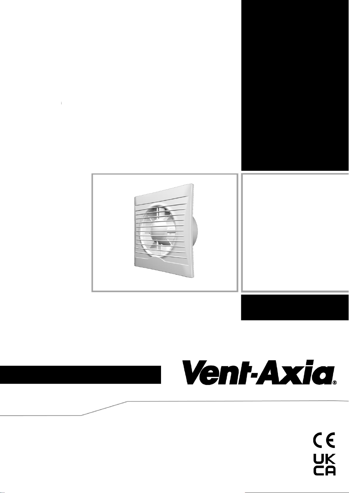
Installation and Wiring Instructions
Stock Ref. N°
439974A (100SV12)
439975A (100SV12T)
439976A (100SV12H)
PLEASE READ INSTRUCTIONS IN CONJUNCTION WITH
ILLUSTRATIONS. PLEASE SAVE THESE INSTRUCTIONS.
Silhouette
SELV 12 RANGE
FAN UNITS 12V 50Hz SELV (CLASS III)
CONTROLLERS 220-240V 50Hz MAINS SUPPLY (CLASS II)
WITH 12V 50Hz SELV OUTPUT
IPX7
Page 2

Installation and Wiring Instructions for the Silhouette SELV 12 Fan & Controller.
IMPORTANT:
READ THESE INSTRUCTIONS
BEFORE COMMENCING THE
INSTALLATION
DO NOT install this product in areas where the following may be present or occur:
• Excessive oil or a grease laden atmosphere.
• Corrosive or flammable gases, liquids or vapours.
• Ambient temperatures higher than 40°C or less than –5°C.
• Possible obstructions which would hinder the access or removal of the Fan.
SAFETY AND GUIDANCE NOTES
A. All wiring to be in accordance with the current I.E.E. Regulations, or the appropriate standards of
your country and MUST be installed by a suitably qualified person.
B. The fan should be provided with a local isolator switch capable of disconnecting all poles, having a
contact separation of at least 3mm.
C. Ensure that the mains supply (Voltage, Frequency, and Phase) complies with the rating label.
D. The fan should only be used in conjunction with the appropriate Vent-Axia products.
E. It is recommended that the connection to the fan connector terminals is made with flexible cable.
F. When the fan is used to remove air from a room containing a fuel-burning appliance, ensure that
the air replacement is adequate for both the fan and the fuel-burning appliance.
G. The fan should not be used where it is liable to be subject to direct water spray for prolonged
periods of time.
H. Where ducted fans are used to handle moisture-laden air, a condensation trap should be fitted.
Horizontal ducts should be arranged to slope slightly downwards away from the fan.
I. This appliance is not intended for use by persons (including children) with reduced physical,
sensory or mental capabilities, or lack of experience and knowledge, unless they have been given
supervision or instruction concerning use of the appliance by a person responsible for their safety.
J. Children should be supervised to ensure that they do not play with the appliance.
K. Stationary appliances not fitted with means for disconnection from the supply mains having a
contact separation in all poles that provide full disconnection under over voltage category III, the
instructions state that means for disconnection must be incorporated in the fixed wiring in
accordance with the wiring rules.
L. The exterior grille should be at least 2.3m above the ground to prevent people from being able to
access moving parts. If the external grille is positioned between 0-2.3m from the ground, Please
use the Vent-Axia wall kit as detailed below to ensure people cannot access the fans impeller from
the outside.
IMPORTANT:- ONLY CONNECT TOGETHER PRODUCTS FROM THE SILHOUETTE
SELV 12 RANGE SINCE THE FANS ARE SPECIALLY DESIGNED TO WORK ON 12V AC
AND ARE NOT COMPATIBLE WITH OTHER VENT-AXIA CONTROLLERS. DO NOT
CONNECT MORE THAN ONE FAN TO THE CONTROLLER.
DESCRIPTION
The Silhouette SELV 12 range from Vent-Axia is a 100mm extract fan for domestic
bathrooms and WC’s available as wall or panel mounted models. Model options with shutter,
timer and auto humidity control.
ACCESSORIES (not supplied)
A range of 100mm wall kits are available for installing into most walls using telescopic liners
supplied. (White – 254102, Brown – 254100)
Page 3

A. INSTALLATION
SITING THE CONTROLLER
1. The controller must not be installed in a shower cubicle or enclosure. It must be sited
away from direct sources of water spray and out of reach (1.5m) of a person using a
fixed bath or shower.
2. Site away from direct sources of heat. Ambient temperature range 0 to 40ºC. Do not
site in an area containing excessive levels of grease.
3. Decide where to site the controller and fan (see section siting the fan), and work out the
required cable runs.
SITING THE FAN
1. The electrical supply to this fan is 12V AC SELV from the mains controller. This means
that the fan may be installed within reach of a person using a fixed bath or shower, i.e.
in a nearby wall. However, the fan must not be placed where it could be submerged in
water or regularly exposed to direct water spray, e.g. from a shower head whether
permanently fixed or movable.
2. Site away from direct sources of heat. Ambient temperature range 0 to 40ºC. Do not
site in an area containing excessive levels of grease.
3. If the fan is installed in a room containing a fuel burning appliance the installer must
ensure that air replacement is adequate for both the fan and the fuel burning appliance.
If the fan is used to supply air into the room the installer must ensure that the fan intake
is located at least 600mm Away from any flue outlet.
4. Ducted Applications. These fans can be used with short lengths of rigid ducting, but
check details first with your Vent-Axia sales centre. Where an excessive amount of
moisture is present in the air, a condensation trap will need to be installed in the
exhaust duct. Horizontal ducts should slope away from the fan unit. Ducts passing
through an unheated roof void should be insulated.
5. A short circuit of the airflow should always be avoided by siting the fan as far away as
possible from and opposite to the main source of air replacement. FIG.1
6. The Silhouette 100SV12H model is fitted with automatic electronic humidity sensing.
The humidity sensor needs free air circulation so do not site close to cupboards, etc.
Do not site above a radiator or other heat source. Do not site where it is liable to be
subject to direct water spray for prolonged periods of time.
PANEL/CEILING MOUNTING
IMPORTANT: The fan should be installed into a closed duct system or protected by an
exterior air grille.
1. Cut a 105mm diameter hole in the fixing surface.
2. Remove the grille by loosening the screw at the bottom of the grille.
3. Mark the screw centres through the holes in the fan back plate. Drill, plug and screw
into position.
4. Securely attach ducting.
5. Replace grille and tighten the screw.
WALL MOUNTING (Wall kit not supplied – see Accessories above)
1. Cut a 115mm diameter hole through the wall and insert the wall sleeve with the large
diameter sleeve on the room side. Slope the sleeve slightly downwards away from the
fan. Cement both ends into position flush with the wall faces.
2. Remove the grille by loosening the screw at the bottom of the grille.
Page 4
3. Mark the screw centres on the wall through the holes of the fan back plate. Drill plug
and screw into position.
4. Repeat for the external grille sub-frame. Fix exterior grille into position with the louvres
positioned downwards.
AFTER INSTALLATION ENSURE IMPELLER ROTATES FREELY
B. WIRING.
WARNING: THE FAN AND ANCILLARY CONTROL EQUIPMENT MUST BE
ISOLATED FROM THE POWER SUPPLY DURING THE INSTALLATION / OR
MAINTENANCE.
IMPORTANT: The controller is only suitable for connection to a 220-240V 50Hz AC
single phase mains electrical supply. It is double insulated (CLASS II) and
therefore must not be earthed. It provides a 12V 50Hz AC Safety Extra
Low Voltage for the Silhouette SELV 12 range of fans. Note that only one
fan must be connected to the controller.
1.5mm² wire is recommended for cable runs up to 8m.
1. Select and follow the appropriate wiring diagram. (Fig. 2,3 or 4)
2. Check all connections have been made correctly and ensure all terminal connections and
cable clamps are securely fastened.
3. Ensure the impeller rotates and is free from obstructions.
C. SETUP
WARNING: THE FAN AND ANCILLARY CONTROL EQUIPMENT MUST BE
ISOLATED FROM THE POWER SUPPLY DURING THE INSTALLATION / OR
MAINTENANCE.
Timer adjustment (Silhouette 100SV12T)
BEFORE ADJUSTING THE TIMER, SWITCH OFF THE MAINS SUPPLY. TIMER SHOULD
ONLY BE ADJUSTED BEFORE OR DURING INSTALLATION.
Unscrew the fixing screws holding the controller to the mounting box. The fan overrun period
can be adjusted up or down using the adjuster located on the internal PCB.
Humidity Set-Point adjustment (Silhouette 100SV12H)
BEFORE ADJUSTING THE CONTROLLER, SWITCH OFF THE MAINS SUPPLY.
HUMIDISTAT SHOULD ONLY BE ADJUSTED BEFORE OR DURING INSTALLATION.
1. Remove the fan grille. The controller is factory set to switch on at about 70% RH.
The humidity set point can be adjusted from 60-95%RH by altering the adjuster
on the control PCB.
2. To LOWER the set-point use a small screwdriver to turn the adjuster
CLOCKWISE. This makes the controller MORE sensitive.
3. To RAISE the set-point use a small screwdriver to turn the adjuster
ANTI-CLOCKWISE. This makes the controller LESS sensitive.
4. Replace the fan grille.
Page 5

Manual Override: The 100SV12H Humidistat has an additional LS connection (connection
made via the transformer) to enable the fan to be manually switched on via a separate light
switch/other controller (Fig.5). (See Fig.4 if not using the LS connection)
IMPORTANT: Upon installation it is possible that the humidity controller will make the fan run
continuously until it has acclimatised to the environment. As part of the installation process it
is important to set/adjust the humidity sensitivity to the desired position. The controller is
already factory set to switch on at about 70% R.H.
LED Operation
The LED will be on whenever the fan is running.
Fig. 1
Fig. 2.
Fig. 3
~ N
1
2
Fan
SILHOUETTE 100 SV12T
2
1
Controller
N
LS
L
SELV Supply
(12V 50Hz)
IMPORTANT "Ls" SIGNAL MUST BE THE SAME PHASE AS THE MAINS INPUT PHASE.
~
N
L
1 Phase Supply
(220-240V 50Hz).
FUSE
Switched
Fused Spur
2
2
1
Controller
1
Fan
SELV Supply
(12V 50Hz)
SILHOUETTE 100 SV12
L
N
Page 6
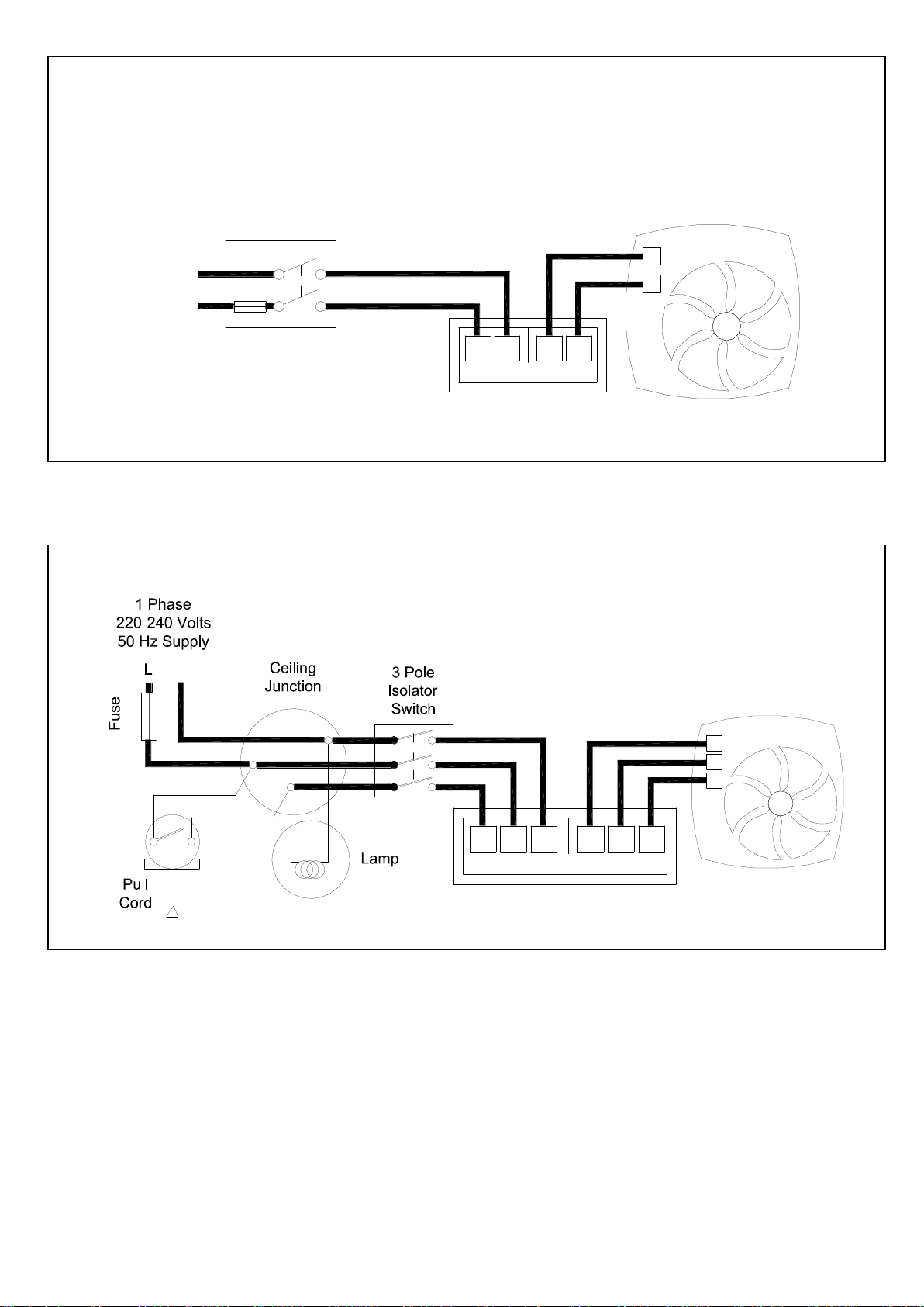
Fig.4
Fig.5
~ N
1
2
Fan
SILHOUETTE 100 SV12H
Controller
N
LS
L
SELV Supply
(12V 50Hz)
3
132
IMPORTANT: Ls SIGNAL MUST BE THE SAME PHASE AS THE MAINS INPUT PHASE
~
N
L
1 Phase Supply
(220-240V 50Hz).
FUSE
Switched
Fused Spur
2
2
1
Controller
1
Fan
SELV Supply
(12V 50Hz)
SILHOUETTE 100 SV12H (Without remote switch)
L
N
Page 7

Page 8
Head Office: Fleming Way, Crawley, West Sussex, RH10 9YX.
EU Authorised Representative: Vent-Axia Bedrijvenweg 17 7442 CX Nijverdal Nederland. [email protected]
UK NATIONAL CALL CENTRE, Newton Road, Crawley, West Sussex, RH10 9JA
SALES ENQUIRIES: Tel: 0344 8560590 Fax: 01293 565169
TECHNICAL SUPPORT: Tel: 0344 8560595 Fax: 01293 539209
For details of the warranty and returns procedure please refer to www.vent-axia.com or write to Vent-Axia, Fleming Way, Crawley, RH10 9YX
403042B 0821
The Guarantee
Applicable only to products installed and used in the United Kingdom. For details of guarantee outside the
United Kingdom contact your local supplier.
Vent-Axia guarantees its products for two years from date of purchase against faulty material or
workmanship. In the event of any part being found to be defective, the product will be repaired, or at the
Company’s option replaced, without charge, provided that the product:-
Has been installed and used in accordance with the instructions given with each unit.
Has not been connected to an unsuitable electricity supply. (The correct electricity supply voltage
is shown on the product rating label attached to the unit).
Has not been subjected to misuse, neglect or damage.
Has not been modified or repaired by any person not authorised by the company.
IF CLAIMING UNDER TERMS OF GUARANTEE
Please return the complete product, carriage paid to your original supplier or nearest Vent-Axia Centre, by
post or personal visit. Please ensure that it is adequately packed and accompanied by a letter clearly
marked “Guarantee Claim” stating the nature of the fault and providing evidence of date and source of
purchase.
The guarantee is offered to you as an extra benefit, and does not affect your legal rights
 Loading...