

Page 1
1
00mm, 120mm & 140mm(150mm) FANS
Installation & Wiring Instructions
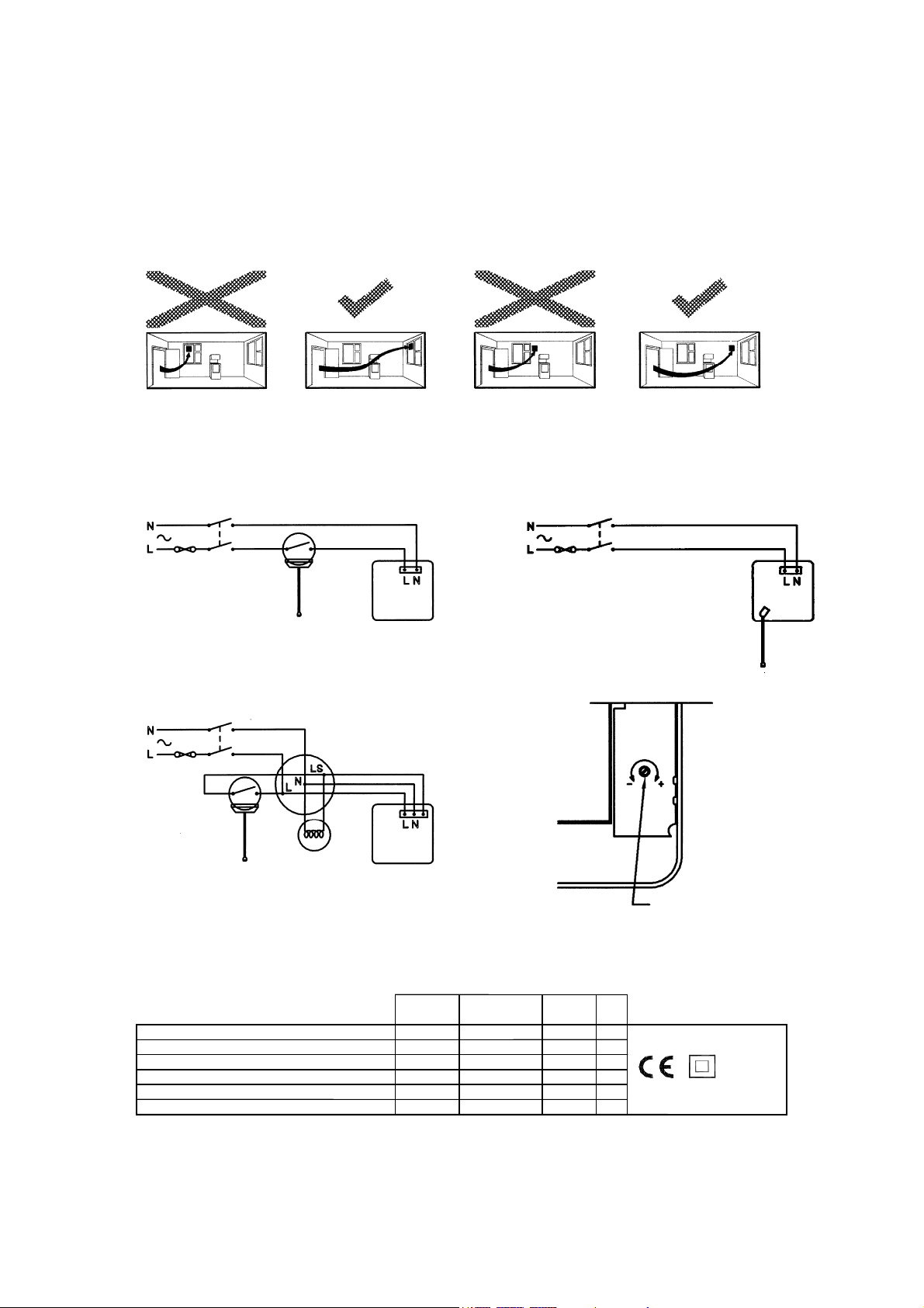
FIG.1.
FIG.2. FIG.3.
FIG.4. FIG.5.
100/100(T,H,P,HP) - (1,2,3,4,5)
100/100(TS,S,HS,PS,HPS) - (1,2,3,4,5) 220-240 50 20 IP44
120/120(T) - (1,2,3,4,5)
120/120(TS,S) - (1,2,3,4,5) 220-240 50 20 IP44
140/140(T,H,P,HP) - (1,2,3,4,5)
140/140(TS,S,HS,PS,HPS) - (1,2,3,4,5) 220-240 50 30 IP34
220-240 50 16 IP44
220-240 50 16 IP44
220-240 50 25 IP34
VOLTAGE FREQUENCY POWER IP
VHzW
ADJUSTMENT
1
Page 2

READ INSTRUCTIONS IN CONJUNCTION WITH THE
ILLUSTRATIONS
IMPORTANT
1. ALWAYS ENSURE THAT THE INSTALLATION CONFORMS TO THE
CURRENT EDITION OF THE IEE WIRING REGULATIONS. BS7671 OR
APPROPRIATE NATIONAL REGULATIONS AND/OR STANDARDS IN
YOUR COUNTRY.
2. THE FAN SHOULD BE SITED AWAY FROM DIRECT SOURCES OF HEAT
IN EXCESS OF 40°C.
3. IF THE FAN IS INSTALLED IN A ROOM CONTAINING A FUEL BURNING
APPLIANCE, THE INSTALLER MUST ENSURE THAT THE AIR
REPLACEMENT IS ADEQUATE FOR BOTH THE FAN AND THE FUEL
BURNING APPLIANCE.
4. WIRING SHOULD BE VIA A SUITABLE 2 POLE ISOLATOR WITH A
SEPARATION OF AT LEAST 3mm. THE FUSE RATING SHOULD BE 3 AMP
(UK ONLY). IF THE EXTRACTOR FAN IS SITED IN A ROOM WITH A FIXED
BATH OR SHOWER, THE SWITCH SHOULD BE LOCATED OUTSIDE THE
ROOM.
5. ALL REGULATIONS AND REQUIREMENTS MUST BE STRICTLY
FOLLOWED TO PREVENT HAZARDS TO LIFE AND PROPERTY BOTH
DURING AND AFTER INSTALLATION, AND DURING ANY SUBSEQUENT
SERVICING AND MAINTAINANCE.
6. MANUFACTURERS OF SOME FLUORESCENT/LOW ENERGY LIGHTING
SYSTEMS INDICATE THAT THESE CAN INTERFERE WITH OTHER
ELECTRONIC/TIMING CIRCUITS. FOR RELIABLE OPERATION WE
RECOMMEND THAT TUNGSTEN FILAMENT LIGHTING IS USED.
7. THIS UNIT MUST ONLY BE FITTED AND ADJUSTED BY SUITABLY
QUALIFIED PERSONNEL.
8. THIS APPLIANCE IS NOT INTENDED FOR USE BY PERSONS
(INCLUDING CHILDREN) WITH REDUCED PHYSICAL, SENSORY OR
MENTAL CAPABILITIES, OR LACK OF EXPERIENCE AND KNOWLEDGE,
UNLESS THEY HAVE BEEN GIVEN SUPERVISION OR INSTRUCTION
CONCERNING USE OF THE APPLIANCE BY A PERSON RESPONSIBLE
FOR THEIR SAFETY.
9. YOUNG CHILDREN SHOULD BE SUPERVISED TO ENSURE THAT THEY
DO NOT PLAY WITH THE APPLIANCE.
10. FANS USED FOR TROPICAL CLIMATES.
11. WHERE THE FAN IS USED TO HANDLE MOISTURE-LADEN AIR, A
CONDENSATION TRAP SHOULD BE FITTED. HORIZONTAL DUCTS
SHOULD BE ARRANGED TO SLOPE SLIGHTLY DOWNWARDS AWAY
FROM THE FAN.
2
Page 3

DESCRIPTION
The 100mm fan is an axial extraction fan suitable for domestic bathrooms and W.C’s. The 120mm fan is suitable
for utility rooms and small kitchens. The 140mm(150mm) fan is suitable for larger kitchens and utility rooms. These
are available as window, wall or panel mounted models with shutter, timer, pull cord and auto-humidity control
option combinations.
Complies with the requirements of European Directives 73/23/EEC (LVD), 89/336/EEC (EMC)
FAN LOCATION
A short circuit of the airflow should always be avoided, Fig.1. by siting the fan as far away as possible from, and
opposite to the main source of, air replacement in the room.
The Humidistat and shuttered Humidistat models are fitted with Automatic Electronic Humidity sensing.
Since the humidity sensor needs free air circulation, do not site close to cupboards etc. Do not site above a
radiator or other heat source.
Pull Cord versions are not suitable for ceiling mounting.
FITTING INSTRUCTIONS
A. PANEL MODEL
1. This model should be installed into a closed duct system or protected by an exterior air grille.
2. Either cut a 105mm diameter hole for 100mm fans, a 125mm diameter hole for 120mm fans or a 155mm
diameter hole for 140mm(150mm) fans.
3. Loosen the screw at the bottom of the grille and remove the front grille. Mark the screw centres through the
holes in the fan back plate. Drill, plug and screw into position.
4. After installation, ensure impeller rotates freely.
B. WINDOW MODEL NOTE:- WHEN INSTALLING A FAN THROUGH A WINDOW CARE SHOULD BE
TAKEN TO ENSURE THAT THE EXTERIOR GRILLE IS AT LEAST 2.3M ABOVE GROUND LEVEL
1. Either cut a 105mm diameter hole in the glass for 100mm fans, a 125mm diameter hole for 120mm fans or a
155mm diameter hole in the glass for 140mm(150mm) fans.
2. Fit spacer(s) as required behind the fan back plate engaging the locating pips in the corner holes.
3. Pass the fan spigot through the hole in the glass from the inside, with a foam gasket on each side of the glass.
4. From the outside place on the remaining spacer, with the locating pips facing outwards. For double-glazing and
materials up to 40mm thick, one or more spacers may be discarded.
5. Draw the assembly together with the threaded fixing ring. Do not over-tighten.
6. Fix the exterior grille in position, using the screws provided, with the louvres pointing downwards.
7. After installation, ensure impeller rotates freely.
C. Wall Model
1. Either cut a 115mm diameter hole for 100mm fans, a 135mm diameter hole for 120mm fans or a 170mm
diameter hole for 140mm(150mm) fans, through the wall and insert the wall sleeve. Slope the sleeve slightly
downwards away from the fan. Cut to length and cement both ends into position flush with the wall faces.
2. Loosen the screw in the bottom of the grille and remove the front grille. Mark the screw centres through the
holes in the fan back plate. Drill, plug and screw into position. Fix exterior grille into position with the louvres
positioned downwards.
3. After installation, ensure impeller rotates freely.
WIRING INSTRUCTIONS
WARNING: ENSURE THAT THE MAINS SUPPLY IS SWITCHED OFF BEFORE MAKING ELECTRICAL
CONNECTIONS.
The extraction fan is suitable for connection to 220-240V 50Hz supply. It is a class ll double insulated product and
MUST NOT be earthed.
Cable entry to the fan should be done through the cable grommet provided, this can be moved for either recessed
wiring through the back of the fan or surface wiring.
Electrical connections depend upon the type of fan being installed and the required mode of operation. After wiring
is complete replace the grille, turn on mains supply and check operation.
A. BASIC FAN / SHUTTERED FAN TYPE
Single speed fan. Controlled by remote switch (e.g. light switch or Auto sensor) Fig.2.
3
Page 4

B. TIMER / SHUTTERED TIMER TYPE
Single speed fan with overrun timer and thermo-electric shutter. The fan must be wired to a lighting circuit switch.
Fig.4.
When switched ‘ON’, the fan will operate at full speed and will continue to run for a pre-set time after the switch is
turned ‘OFF’.
TIMER ADJUSTMENT
BEFORE ADJUSTING THE TIMER, SWITCH OFF THE MAINS SUPPLY. TIMER SHOULD ONLY BE
ADJUSTED BEFORE OR DURING INSTALLATION
.
1. Remove the fan grille. The controller is factory set at 15 minutes approx.
2. To REDUCE the operating time, use a small screwdriver to turn the adjuster Fig.5. ANTI-CLOCKWISE.
3. To INCREASE the operating time, use a small screwdriver to turn the adjuster Fig.5. CLOCKWISE.
4. Replace the fan grille.
C. HUMIDISTAT / SHUTTERED HUMIDISTAT TYPE
The fan contains an integral humidity controller. In automatic mode the controller switches the fan on at full speed
when the room Relative Humidity (RH) reaches the set-point. The fan will continue to run until the room RH falls
below the set-point.
The integral pull cord or remote switch will switch between automatic humidity control and manual override. There
is no permanent OFF position.
Use Fig.3. for wiring the fan for manual override using the internal pullswitch. Use Fig.4. for wiring with a remote
switch when the pull cord should be switched to the automatic position, (indicator off), and the cord cut off.
PLEASE NOTE:-
Upon installation it is possible that the humidity controller will make the fan run continuously until it has
acclimatised to the environment.
Humidity Set-Point adjustment
BEFORE ADJUSTING THE CONTROLLER, SWITCH OFF THE MAINS SUPPLY. HUMIDISTAT SHOULD
ONLY BE ADJUSTED BEFORE OR DURING INSTALLATION
1. Remove the fan grille. The controller is factory set to switch on at about 72% RH.
2. To LOWER the set-point use a small screwdriver to turn the adjuster Fig.5. ANTI-CLOCKWISE. This makes
the controller MORE sensitive.
3. To RAISE the set-point use a small screwdriver to turn the adjuster Fig.5. CLOCKWISE. This makes the
controller LESS sensitive.
4. Replace the fan grille.
.
NOTE! DO NOT TOUCH HUMIDITY SENSOR NEXT TO THE LED.
Shutter Operation
With the shuttered fan types the shutters will open approximately one minute after the fan is turned on. The shutter
will close about a minute after the fan is switched off.
Pull Cord Versions
Before replacing the fan grille, make sure that the pull-cord is lying to the left of the pillar and passes through the
cord guide slot.
This product should not be disposed of with household waste. Please recycle where
facilities exist. Check with your local authority for recycling advice.
449235B 0414
APL UK LTD
4
 Loading...