

Page 1
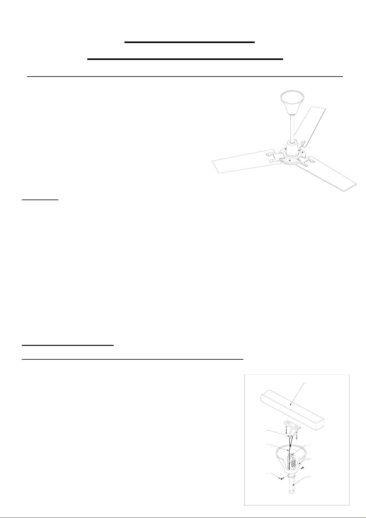
Ceiling Sweep Fan
Fitting & wiring Instructions
PLEASE READ ALL INSTRUCTIONS CAREFULLY BEFORE COMMENCING INSTALLATION
This instruction leaflet covers the following sized fans
900mm (36”)
1200mm (48”)
1400mm (56”)
All sizes are supplied with 2 downrod lengths
400mm Downrod fitted giving 610mm overall drop
(From ceiling to base of motor body)
150mm Downrod supplied loose giving 360mm overall drop
(From ceiling to base of motor body)
IMPORTANT
THE FAN MUST BE SITED AND CONNECTED IN ACCORDANCE WITH CURRENT IEE REGULATIONS (UK) OR THE APPROPRIATE
STANDARDS IN YOUR COUNTRY.
THIS APPLIANCE MUST BE EARTHED
THE APPLIANCE IS NOT INTENDED FOR USE BY YOUNG CHILDREN OR INFIRM PERSONS WITHOUT SUPERVISION.
YOUNG CHILDREN SHOULD BE SUPERVISED TO ENSURE THAT THEY DO NOT PLAY WITH THE APPLIANCE.
CHECK THAT THE VOLTAGE AND FREQUENCY ON BOTH THE FAN MOTOR AND CONTROLLER (IF FITTED) RATING LABELS
CORRESPOND WITH YOUR ELECTRICITY SUPPLY.
THE INSTALLATION MUST BE PROVIDED WITH A DOUBLE POLE ISOLATOR SWITCH HAVING A CONTACT SEPARATION OF NOT LESS
THAN 3MM AND PROTECTED WITH A 5 AMP FUSE (UK).
ENSURE THAT THE SAFETY WIRE IS CONNECTED TO THE J-HOOK BRACKET BEFORE OPERATING FAN.
ALL INSTALLATION AND ELECTRICAL CONNECTION WORK MUST BE CARRIED OUT BY A SUITABLY QUALIFIED PROFESSIONAL
PERSON.
THE SHORTER (150mm) DOWN ROD LENGTH SHOULD ONLY BE USED WHERE FANS ARE TO BE MOUNTED TO BEAMS BELOW THE
CEILING OR ROOF.
INSTALLING THE CEILING FAN
(Ensure that the mains supply is isolated before proceeding with the wiring)
1.Decide on the position the fan is to be sited; it must be a minimum of 2.3m
from the floor to the lowest point on the fan. ( A shorter 150mm long downrod is
supplied with the fan if required. Refer to the section on installing the shorter downrod).
2. Fix the ceiling J-hook (supplied) firmly to a timber joist or concrete ceiling with
the coach screws supplied (Or similar). Ensure that the fixing bracket in the ceiling
is able to support a hanging weight of 15kg minimum.
(Fig A)
3. Fit the three blades to the fan body (see Diagram Fig B)
4. Hang the fan on the hook with the safety wire, then hook up the fan on the
black rubber roller making sure that all wires are clear.
5. Connect supply wires to the fan using the terminal block at the top of the downrod.
(See wiring Diagram Fig C)
6. The size of supply wires is 0.5 and 0.75mm² for flexible cord, 1 to 2.5mm² cable for
fixed wiring
CEIL ING JOIST
MUST BE ABLE TO
SUPPORT A
MINIMUM OF 15kg
THE SURFACE MUST
BE HORIZONTAL
J-HOOK
SAFETY
WIRE
SCREWS
RUBBER ROLLER
UPPER CANOPY
(SHOWN BROKEN)
DOWNROD
Fig A
Page 2
7. Secure upper canopy with the screws fitted
to cover the wiring connections.
8. Tighten all screws including the earth connections.
9.Switch on supply and check fan function
.
FAN BLADE
MOUNTING SCREWS
SPRING WASHERS
FAN BLADE MOUNTING
GASKET
FAN BLADE
FAN MOTOR BODY
Fig B
CEIL ING
FAN
STANDARD
ROTATION
(DOWNWARD AIRFLOW)
LF LR
N
CEILING
FAN
REVERSE
ROTATION
(UPWARD AIRFLOW)
N
LRLF
Fig C
1 PHASE SUPPLY
(220-240V 50Hz)
N
L
N
L
1 PHASE SUPPLY
(220-240V 50Hz)
INSTRUCTIONS FOR CHANGING TO SHORTER 150mm DOWNROD
Ensure that the mains supply is isolated before proceeding
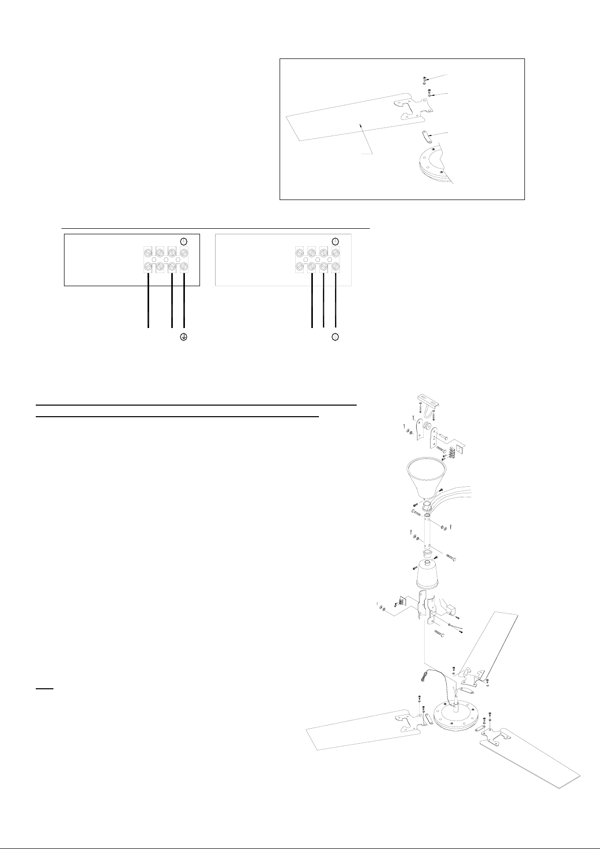
1. Loosen the lower canopy screws and slide canopy up the downrod.
2. Disconnect the Brown (LF) Red (LR) and Blue (N), which run up the downrod
from the lower terminal block located just above fan motor body.
3. Disconnect the Earth (Green/Yellow) wire from the lower mounting bracket which
also runs up inside of downrod.
4. Carefully remove split pin and downrod securing bolt.
5. Loosen the upper canopy screws and slide canopy down the downrod.
6. Carefully remove the split pin and downrod securing bolt and then disconnect the
Earth wire.
7. Carefully remove existing downrod passing the disconnected feed wires through
the rod along with the safety wire.
8. Replace with the 150mm long downrod supplied.
9. Pass the feed wires through the new Rod along with the safety wire.
10. Replace the upper and lower downrod securing bolts and split pins.
11. The feed wires will need to be cut and stripped to suit the shorter rod. And
re-connected as follows to the lower terminal block Brown (LF) Red (LR) and Blue (N).
12. Re-connect all Earth (Green/Yellow) wires.
13. Because the shorter downrod has been required for your particular installation,
It is important that the safety wire is reduced in length to protrude 75mm above the
Height of the 150mm downrod. The loop for the safety wire will need re-making by
using a wire rope grip or crimp. (Supplied by others) It is essential that the new
safet y wi re loop will wi thstand th e wei ght of the fan in the event of it falling.
IMPORTANT
ALL
FIXINGS MUST BE TIGHT BEFORE OPERATING THE FAN
IT IS ADVISABLE TO CHECK/INSPECT ALL THE FIXINGS
ANNUALLY, AND RE-TIGHTEN AS NECESSARY
.
This Fan is guaranteed for one year from date of purchase against
Faulty material or workmanship. In the event of any part being found
To be defective please contact your local supplier stating the nature of
the fault and providing evidence of date and source of purchase.
428242C 0607
2
 Loading...