

Page 1
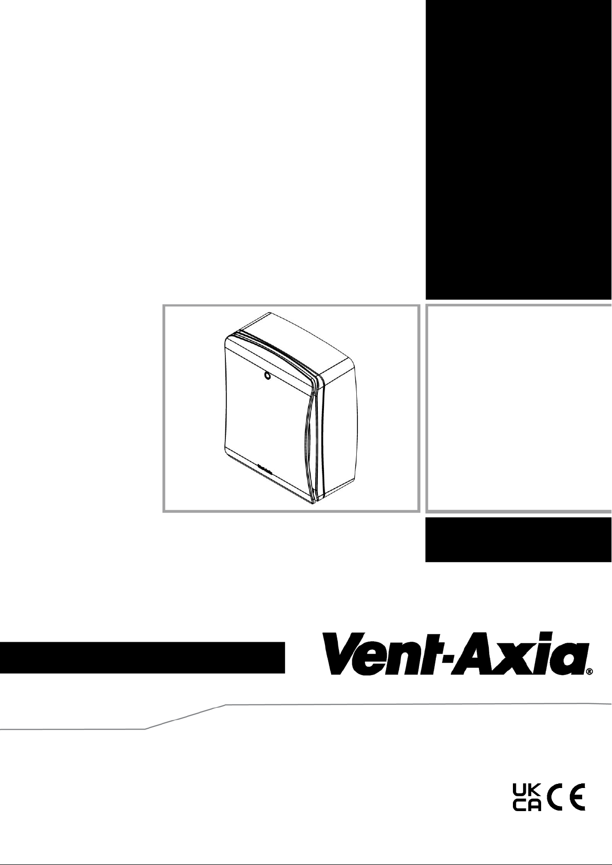
Lo-Carbon
SOLO Plus
Centrifuga
Bathroom
Stock Ref. N°
427481B (P)
427482B (T)
427483B (HT)
427484B (TM)
Installation and Wiring Instructions
T IPX4
220-240V~50Hz
l
/Toilet Fan
PLEASE READ INSTRUCTIONS IN CONJUNCTION WITH THE ILLUSTRATIONS.
PLEASE SAVE THESE INSTRUCTIONS
Page 2

2
Installation and Wiring Instructions for the SOLO Plus Bathroom Extract Fan.
IMPORTANT:
READ THESE INSTRUCTIONS
BEFORE COMMENCING THE
INSTALLATION
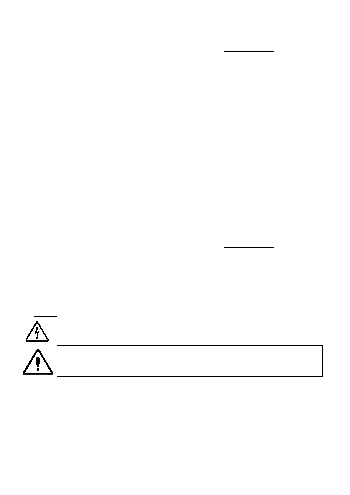
DO NOT install this product in areas where the following may be present or occur:
• Excessive oil or a grease laden atmosphere.
• Corrosive or flammable gases, liquids or vapours.
• Ambient temperatures higher than 40°C or less than –5°C.
• Possible obstructions which would hinder the access or removal of the Fan.
SAFETY AND GUIDANCE NOTES
A. All wiring to be in accordance with the current I.E.E.
Regulations, or the appropriate s t a ndards of your
country and MUST be installed by a suitably qualified
person.
B. The Fan should be provided with a loc a l isolator
switch capable of disconnecting all poles, having a
contact separation of at least 3mm.
C. Ensure that the mains supply (Voltage, Frequency,
and Phase) complies with the rating label .
D. The Fan should only be used in conjunc t i on wit h t he
appropriate Vent-Axia product s .
E. It is recommended that the connection to the fan
connector terminals is made with flexible cable.
F. When the Fan is used to remove air from a room
containing a fuel-burning applia nce, ensure that the air
replacement is adequate for both the fan and the fuelburning appliance.
G. The Fan should not be used where it is li abl e t o be
subject to direct water spray for prolo nged periods of
time.
H. Where ducted Fans are used to handle mois t ure-
laden air, a condensation trap should b e fi t t e d.
Horizontal ducts should be arranged to slope slightly
downwards away from the Fan.
Page 3

3
I. This appliance is not intended f or use by persons
(Including children) with re duc e d phy sical, sensory or
mental capabilities, or lack of experience and
knowledge, unless they have be en giv e n s upervision or
instruction concerning use of t he appliance by a person
responsible for their safety.
J. Young children should be superv i s ed t o ensure that they
do not play with the appliance.
K. Fans used for tropical climates.
DESCRIPTION
As standard, the SOLO Plus is suitable for panel/wall installations, flush or surface mounting, either in a horizontal or
vertical plane. 100mm ducting (flexible or straight ) can be attached using the supplied adjustable spigot , providing
rear or side exit options. Adaptors for System 25 and System 50 ducting can be used in conjunction with the
adjustable spigot. For wall installations a Wall Kit (25 41 02 White / 25 41 00 Brown) can be used. An optional f il ter is
also available (449265). Please see our catalogue or web site (www.vent-axia.com) for more information on System
25/50 and for alternative ducting and termination options.
A. INSTALLATION
PANEL MOUNTING (Surface)
1. Cut a 105mm∅ hole through the panel, ensuring that there is sufficient space for the product to be installed and
that the filter can be removed for maintenance.
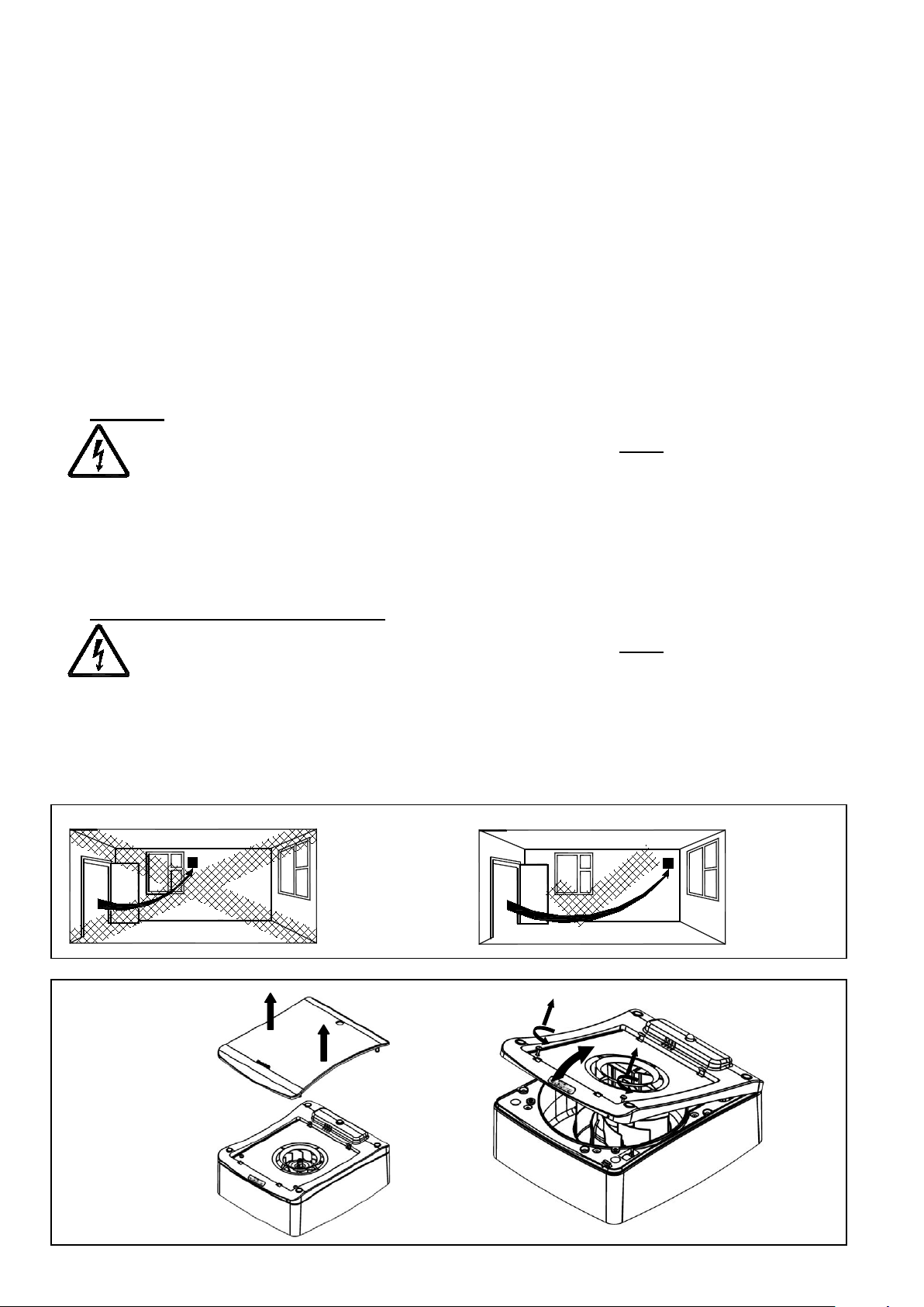
2. Removing the grille, Firstly remove the front cover by carefully pul l ing each corner of the front panel until it is free
to be removed from the inner grille (Fig 1). Unscrew the two screws at the bott om of the inner grille. The screws
will remain in the inner grille but will be loose when the grille is ready to be removed (Fig 1). Lift t he i nner grille
from the bottom edge ensuring not to damage the sensor ca bl e (TM model only) attached to the front assembly
and Base Housing (Fig 6).
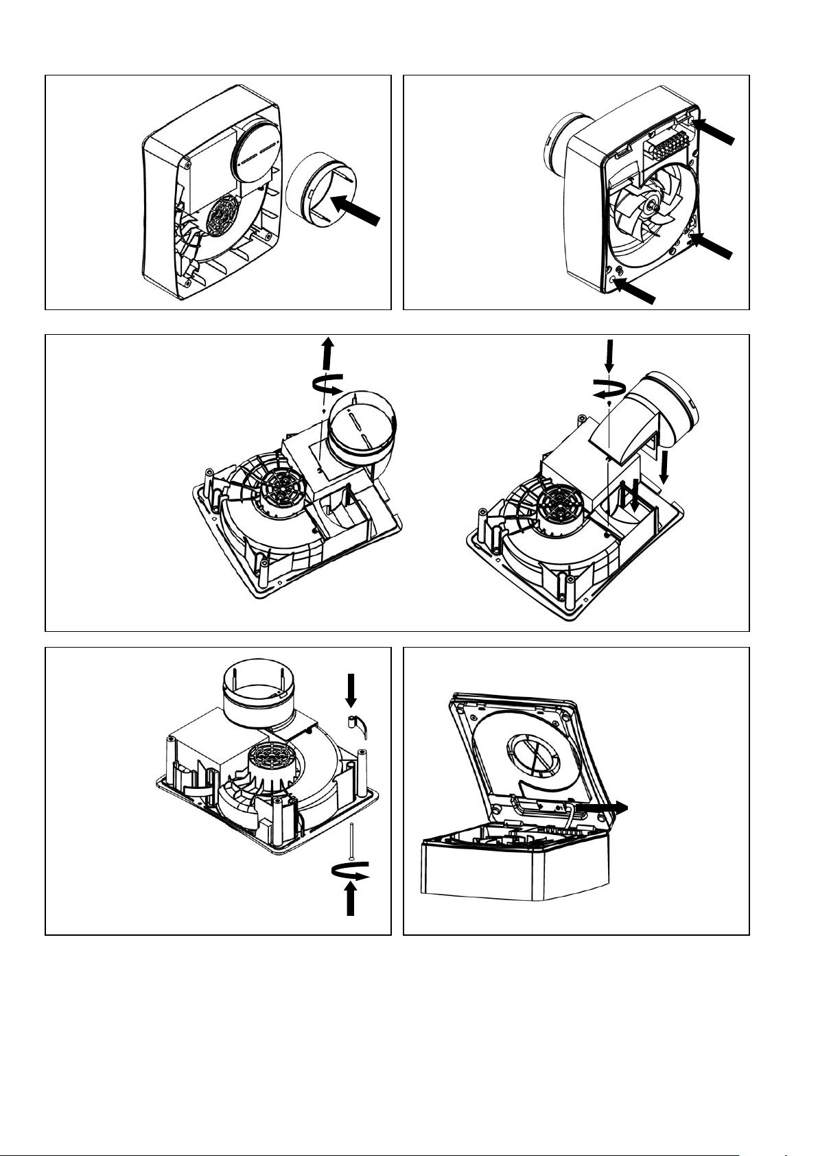
3. Remove the Spigot Ring from inside the carton and clip over the Spigot Adaptor making sure the lip on the
Spigot Ring locates firmly inside the groove on the Spigot A daptor (Fig 2). Ensure that the Spigot Adaptor is
firmly located onto the Base Housing and the shutter is still securely fastened and fully functional.
4. Set-up the appropriate speed selection and other features a s out l ined in Section B SETUP.
5. Attach the ducting to the Spigot and locate into the hol e i n the panel ensuring the Skirt is located co rrectly into
the Base Housing. Secure into position using appropriate fixtures (Fig 3).
6. Ensure the Impeller rotates freely.
7. Select and follow the appropriate wiring diagram in S ectio n C WI RING.
8. Replace the inner grille ensuring that the PIR sensor cable (TM model only) is reconnected to the PIR sensor
PCB (Fig 6). Replace the front panel.
9. Switch the mains power supply on and check the fan i s oper ating correctly.
PANEL MOUNTING (Flush)
1. Mark and cut a rectangular hole (190mm x 240mm) through the panel, ensuring that there is sufficient space for
the product to be installed and that the filter (If fitted) can be removed for maintenance. IMPORTANT: Be careful
to avoid joists and hidden cables.
2. Removing the grille, Firstly remove the front cover by carefully pull ing each corner of the front panel until it is free
to be removed from the inner grille (Fig 1). Unscrew the two screws at the bott om of the inner grille. The screws
will remain in the inner grille but will be loose when the grille is ready to be removed (Fig 1). Lift the i nner grille
from the bottom edge ensuring not to damage the sensor ca bl e (TM model only) attached to the front assembly
and Base Housing (Fig 6).
3. Remove the Spigot Ring from inside the carton and cli p over the Spigot Adaptor, making sure the lip on the
Spigot Ring locates firmly inside the groove on the Spigot A daptor (Fig 2). The Spigot can be repositioned for
side exit installations by removing the screw and slidi ng the spigot away from the rear of the Base Housing,
carefully observing the guide rails (Fig 4). The Spigot can then be rotated and repositioned for side ex i t using the
same guide rails and retaining screw (Fig 4). Ensure that the Spigot Adaptor is firmly located onto the Base
Housing in the required orientation and the shutter is still securely fastened and fully functional.
Page 4
4
4. Remove the Skirt and pass the supplied screw fully t hrough the flange of the base housing. Then attach the 3
IMPORTANT
Once complete after approximately 2 minutes, the fan will run as normal.
supplied Panel Clips (Fig 5). and partially screw i nt o place until they are properly retained (allowing enough gap
for the panel thickness).
5. Set-up the appropriate speed selection and other features a s out l ined in Section B SETUP.
6. Attach the ducting to the Spigot and locate into the hol e i n the panel, ensuring the cable is fed into the Base
Housing and the Panel Clips spring out behind the pa nel.
7. Secure into position by carefully tightening the Panel Clips. It maybe necessary to hold the product c entrally in
the hole while tightening so that no gaps are seen onc e t he cov er is on. IMPORTANT: If power tools are used,
set them to the minimum torque setting or preferably use a manual screwdriver. Do not over tighten.
8. Ensure the Impeller rotates freely.
9. Select and follow the appropriate wiring diagram in S ectio n C WI RING.
10. Replace the inner grille ensuring that the PIR sensor cable (TM model only) is reconnected to the PIR sensor
PCB (Fig 6). Replace the front panel.
11. Switch the mains power supply on and check the fan is operating correctly.
WALL MOUNTING (Surface) For wall installations a Wall Kit (25 41 02 White / 25 41 00 Brown) can be used.
1. Cut a 115mm. ∅ hole through the wall, ensuring that there is sufficient space for the product to be installed and
that the filter (if fitted) can be removed for maintenance.
2. Insert the wall sleeve with the smaller diamet er sleeve on the room-side and cement both ends into posit ion flush
with the wall faces. The wall sleeve should be angled downwards, away from the fan, to allow any condensati on
to drain to the outside wall.
3. Outside Grille: Using the Back Plate as a template, m ark the fixing hole centres on the wall. Drill and plug the
wall and fix the Back Plate into position.
4. Fix the Outside Grille on to the Back Plate (screws provided). Ensure the louvres are pointing downwards.
5. Removing the grille, Firstly remove the front cover by carefully pull ing each corner of the front panel until it is free
to be removed from the inner grille (Fig 1). Unscrew the two screws at the bott om of the inner grille. The screws
will remain in the inner grille but will be loose when the grille is ready to be removed (Fig 1). Lift the inner grille
from the bottom edge ensuring not to damage the sensor ca bl e (TM model only) attached to the front assembly
and Base Housing (Fig 6).
6. Remove the Spigot Ring from inside the carton and clip over the Spigot A daptor making sure the lip on the
Spigot Ring locates firmly inside the groove on the Spigot A daptor (Fig 2). Ensure that the Spigot Adaptor is
firmly located onto the Base Housing and the shutter is still securely fastened and fully functional.
7. Set-up the appropriate speed selection and other features a s out l ined in Section B SETUP.
8. Using the Base Housing as a template, mark the f i xing hole centres on the wall, carefully sliding the spigot i nt o
the Wall Liner. Secure the Base Housing into position using the screws and fixings provided ensuring the S kirt is
located correctly into the Base Housing (Fig 3)
9. Ensure the Impeller rotates freely.
10. Select and follow the appropriate wiring diagram in Section C WIRING.
12. Replace the inner grille ensuring that the PIR sensor cable (TM model only) is reconnected to the PIR sensor
PCB (Fig 6) Replace the front panel.
13. Switch the mains power supply on and check the fan is operating correctly.
B. SETUP
WARNING: THE FAN AND ANCILLARY CONTROL EQUIPMENT MUST BE ISOLATED FROM THE
POWER SUPPLY DURING THE INSTALLATION / OR MAINTENA NCE.
On first power up, the fan will run through its initialization routine.
On T, HT & TM models the fan will switch on and off during this routine (Including the LED)
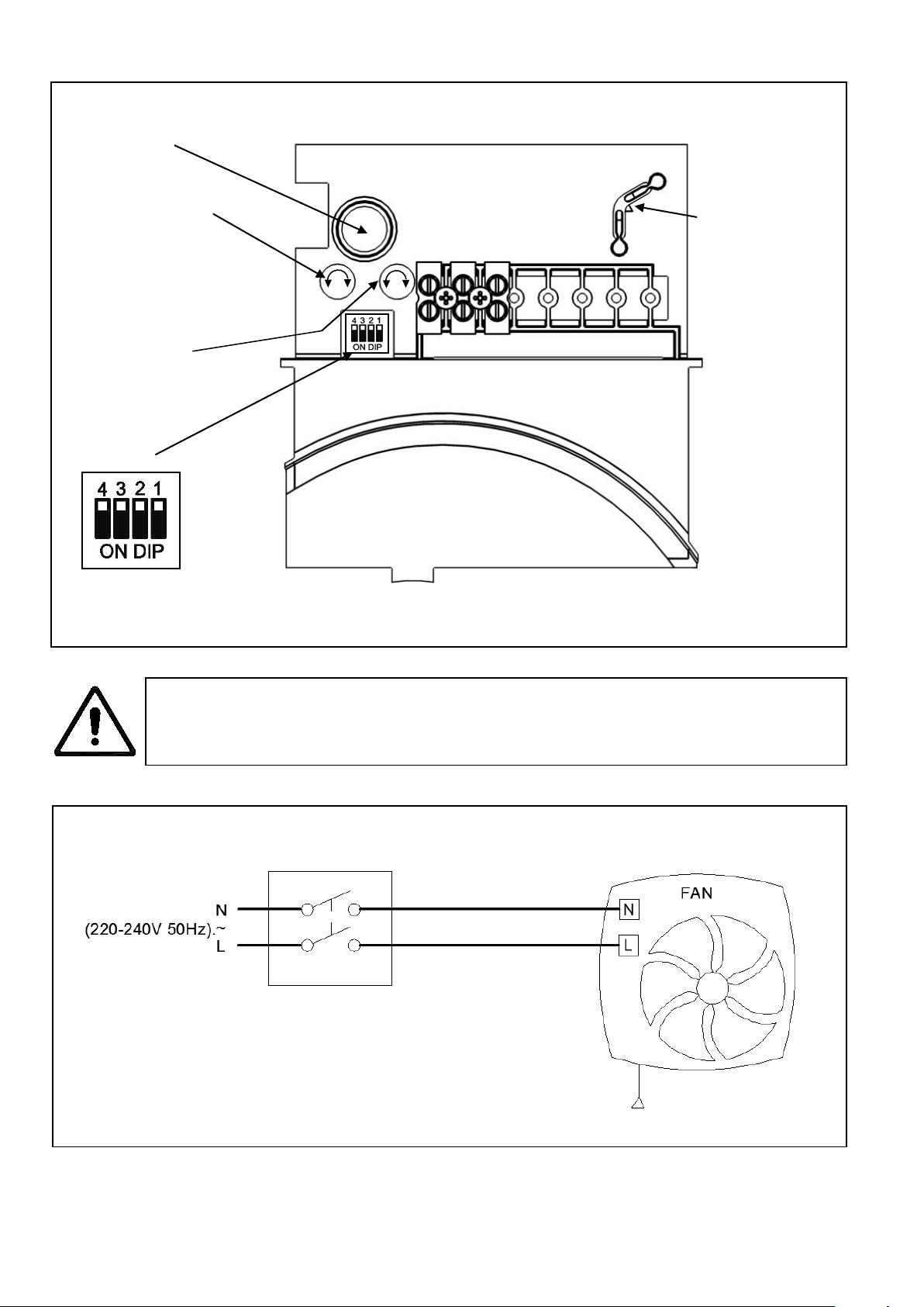
1. SELECTING THE CONSTANT TRICKLE OPTION -
trickle operation. To disable the cons tant trickle option, move dip switch 2 into the OFF position (Fig 7) .
2. SELECTING THE TRICKLE SPEED (if enabled)
This will determine the speed at which the fan will run continuously if the constant trickle speed option is enabled (1 above).
• Low trickle speed – Switch dip switch 1 into the OFF position (F ig 7).
• High trickle speed – Switch dip switch 1 into the ON position (Fig 7).
3. SELECTING THE INSTALLATION RUNNING MODE
This will determine the speed at which the fan will run when activated by either the Pull-cord/LS line/Hum i dity/PIR.
• Wall mode – Switch dip switch 3 into the OFF position (Fig 7)
• Ducted mode – Switch dip switch 3 into the ON position (Fig 7)
Switch dip switch 2 into the ON posit ion to activate the constant
Page 5
5
Fig. 1.
4. SELECTING THE DELAY-ON OPTION (T and HT models) -
delay-on feature. This will pre v ent the fan from going to boost for approximately 2 minutes. If the Switch Live is disconnected
(switched off) within this period the fan will not boost. If the Switch Live is still active after the period t he fan will boost. (Fig 7).
5. TIMER ADJUSTMENT (T, HT, TM models)
The overrun time period is factory set to 15 minutes. The overrun time per i od may be adjusted from 5-30 minutes by a ltering
the adjuster on the control PCB [T ] ( Fig 7).
i. To REDUCE the operating time, turn the adjuster [T] ANTI-CLOCKWISE (Fig 7).
ii. To INCREASE the operating time, turn the adjuster [T] CLOCKWISE ( Fig 7).
5. HUMIDITY ADJUSTMENT (HT model)
The fan’s Humidity Set-Point is factory set to switch the fan on at 72%RH (Fig 7).
i. To LOWER the Set-Point, turn the Humid i ty Adjuster [H] ANTI-CLOCKWISE. This makes the fan more sensitive to RH % ,
i.e. the fan will come on at a lower RH% (Fi g 7).
ii. To RAISE the Set-Point, turn the Humidity Adjuster [H] CLOCKWISE. This makes the fan less sensitive to RH%, i.e. the
fan will come on at a higher RH% (Fig 7).
Switch dip switch 4 into the ON position to activate the
C. WIRING.
WARNING: THE FAN AND ANCILLARY CONTROL EQUIPMENT MUST BE ISOLATED FROM THE
POWER SUPPLY DURING THE INSTALLATION / OR MAINTENA NCE.
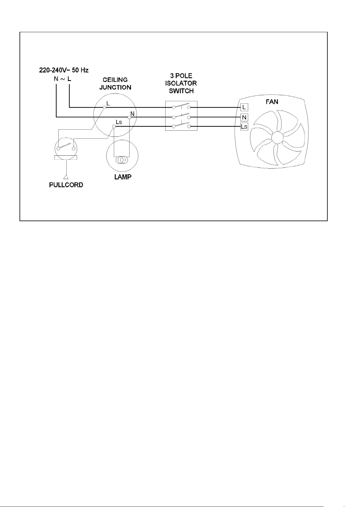
1. Select and follow the appro priate wiring diagrams (Fig 8-9)
2. It may be necessary to feed the mains cable around between the outside of the B ase Housing and the Skirt to prevent the
cable from being trapped.
3. Check all connections hav e been made correctly and ensure all ter m inal connections and cable clamps are securely
fastened.
4. Ensure the impeller rotates and is free from obstructions.
D. SERVICING AND MAINTENANCE.
WARNING: THE FAN AND ANCILLARY CONTROL EQUIPMENT MUST BE ISOLATED
FROM THE POWER SUPPLY DURING MAINTENANCE.
1. At intervals appropriate to the installation, the fan should be inspected and if required cleaned to ensure there is no build-up
of dirt or other deposits.
2. If a filter is fitted, remove the filter and wash in warm soapy water.
3. Wipe the inlets and front face with a damp cloth until clean.
4. Once the filter is dry it can be replaced.
The fan has sealed for life bearings, which do not require lubrication.
Removing the grille
Page 6
6
To remove the
Fig. 2.
Fig. 3.
Fig. 4.
Fig. 6. PIR sensor cable - (TM only)
Fig. 5.
Attaching the
Spigot.
Converting outlet
spigot for side exit
and recess mounting.
Recess mounting clips
In 3 positions
Surface mounting
screw hole locations
cover on TM
models the
sensor
lead must be
disconnected
Page 7
7
Fig. 8.
Fig. 7. Settings Top view of PCB cover showing pot locations
4 = Delay-On timer on or off (Not on TM model)
Cable clamp
wiring.
LED position
Timer adjuster
Turn anti-clockwise.
T
To increase time
Humidity adjuster
Dip switch
settings
H + + - -
L N LS
Pullcord on
P model only
IMPORTANT
Once complete after approximately 2 minutes, the fan will run as normal.
And dip switch location
(T/HT/TM Models)
To reduce time
Turn Clockwise.
(HT Model)
To LOWER the set-point
Turn Anti-clockwise.
To RAISE the set-point
Turn clockwise.
1 = Trickle speed
2 = Constant trickle on or off
3 = Wall or Duct mode
On first power up, the fan will run through its initializat i on routine.
On T, HT & TM models the fan will switch on and off during this routine (Including the LED)
P/TM wiring diagram
HT (T Disabled)
must be used
with surface
Page 8
8
Fig. 9. T/HT wiring diagram
Page 9

9
PRODUCT FICHE
Name:
Vent-Axia
Vent-Axia
Vent-Axia
Vent-Axia
SEC Class F E C C
SEC Value ('Average')
13.97
15.72
26.23
26.23
SEC Value ('Warm')
6.32
7.11
11.86
11.86
SEC Value ('Cold')
27.32
30.75
51.31
51.31
Label Required? (Yes/No=Out of scope)
No
No
No
No
Declared as: RVU or NRVU/UVU or BVU
RVU-UVU
RVU-UVU
RVU-UVU
RVU-UVU
Speed Drive
Multi-Speed
Multi-Speed
Multi-Speed
Multi-Speed
Type HRS (Recuperative, Regenerative, None)
None
None
None
None
Thermal Eff: [ (%), NA(if none)]
N/A
N/A
N/A
N/A
Max. Flow Rate (m3/h)
75.60
75.60
75.60
75.60
Max. Power Input (W): (@Max.Flow Rate)
8.40
8.40
8.40
8.40
LWA: Sound Power Level (dB)
51.02
51.02
51.02
51.02
Ref. Flow Rate (m3/s)
0.01
0.01
0.01
0.01
Ref. Pressure Diff. (Pa)
N/A
N/A
N/A
N/A
SPI [W/(m3/h)]
0.16
0.16
0.16
0.16
Control Factor & Control Typology: (CTRL/
Typology)
Control Factor; CTRL
1.00
0.95
0.65
0.65
Local Demand
Control
Local Demand
Control
Declared: -Max Internal & External Leakage
regenerative heat exchangers only),
-&Ext. Leakage Rates (%) for Ducted UVUs;
Mixing Rate of Non-Ducted BVUs not intended
either supply or extract air side;
Position and description of visual filter warning
of the unit
Internet Address (for Disassembly Instructions)
www.vent-axia.com
www.vent-axia.com
www.vent-axia.com
www.vent-axia.com
Sensitivity p. Variation@+20/-20 Pa: (for NonDucted Vus)
Air Tightness-ID/OD-(m3/h) (for Non-Ducted
Vus)
Annual Electricity Consumption: AEC (kWh/a)
2.19
2.03
1.15
1.15
Annual Heating Saved: AHS (kWh/a)
AHS: Warm
6.32
7.11
11.86
11.86
AHS: Cold
27.32
30.75
51.31
51.31
For Residential Ventilation Units (Complying Comm ission Delegated Regulation (EU) No 1254 /2014)
Model ID (Stock Ref.) :
Control Typology Manual Control Clock Control
Rates(%) for BVUs or carry over (for
Lo-Carbon Solo Plus
P - 427481
N/A N/A N/A N/A
Lo-Carbon Solo Plus
T - 427482
Lo-Carbon Solo Plus
HT - 427483
Lo-Carbon Solo Plus
TM - 427484
to be equipped with one duct connection on
for RVUs intended for use with filters, including
text pointing out the importance of regular filter
changes for performance and energy efficiency
For UVUs (Instructions Install Regulated
Supply/Extract Grilles Façade)
AHS: Average 13.97 15.72 26.23 26.23
N/A N/A N/A N/A
N/A N/A N/A N/A
In F&W In F&W In F&W In F&W
N/A N/A N/A N/A
N/A N/A N/A N/A
Page 10

10
Notes:-
Page 11

11
Page 12
12
The Guarantee
Applicable only to products installed and used in the United Kingdom. For details of guarantee outside the United Kingdom contact
Vent-Axia guarantees its products for two years from date of purchase against faulty material or workmanship. In the event of any part being found
to be defective, the product will be repaired, or at the Company’s option replaced, without charge, provided that the product:-
• Has been installed and used in accordance with the instructions given with each unit.
• Has not been connected to an unsuitable electricity supply. (The correct electricity supply voltage is shown on the product rating label
attached to the unit).
• Has not been subjected to misuse, neglect or damage.
• Has not been modified or repaired by any person not authorised by the company.
IF CLAIMING UNDER TERMS OF GUARANTEE
Please return the complete product, carriage paid to your original supplier or nearest Vent-Axia Centre, by post or personal visit. Please ensure
that it is adequately packed and accompanied by a letter clearly marked “Guarantee Claim” stating the nature of the fault and providing evidence of
date and source of purchase.
The guarantee is offered to you as an extra benefit, and does not affect your legal rights
your local supplier.
Head Office: Fleming Way, Crawley, West Sussex, RH10 9YX.
EU Authorised Representative: Vent-Axia Bedrijv enweg 17 7442 CX Nijverdal Nederland. [email protected]
UK NATIONAL CALL CENTRE, Newton Road, Crawley, West Sussex, RH10 9JA
SALES ENQUIRIES: Tel: 0344 8560590 Fax: 01293 565169
TECHNICAL SUPPORT: Tel: 0344 8560595 Fax: 01293 539209
For details of the warranty and returns procedure please refer to www.vent-axia.com or write to Vent-Axia Ltd, Fleming Way, Crawley, RH10 9YX
448519F 0721
 Loading...