

Page 1
DESCRIPTION
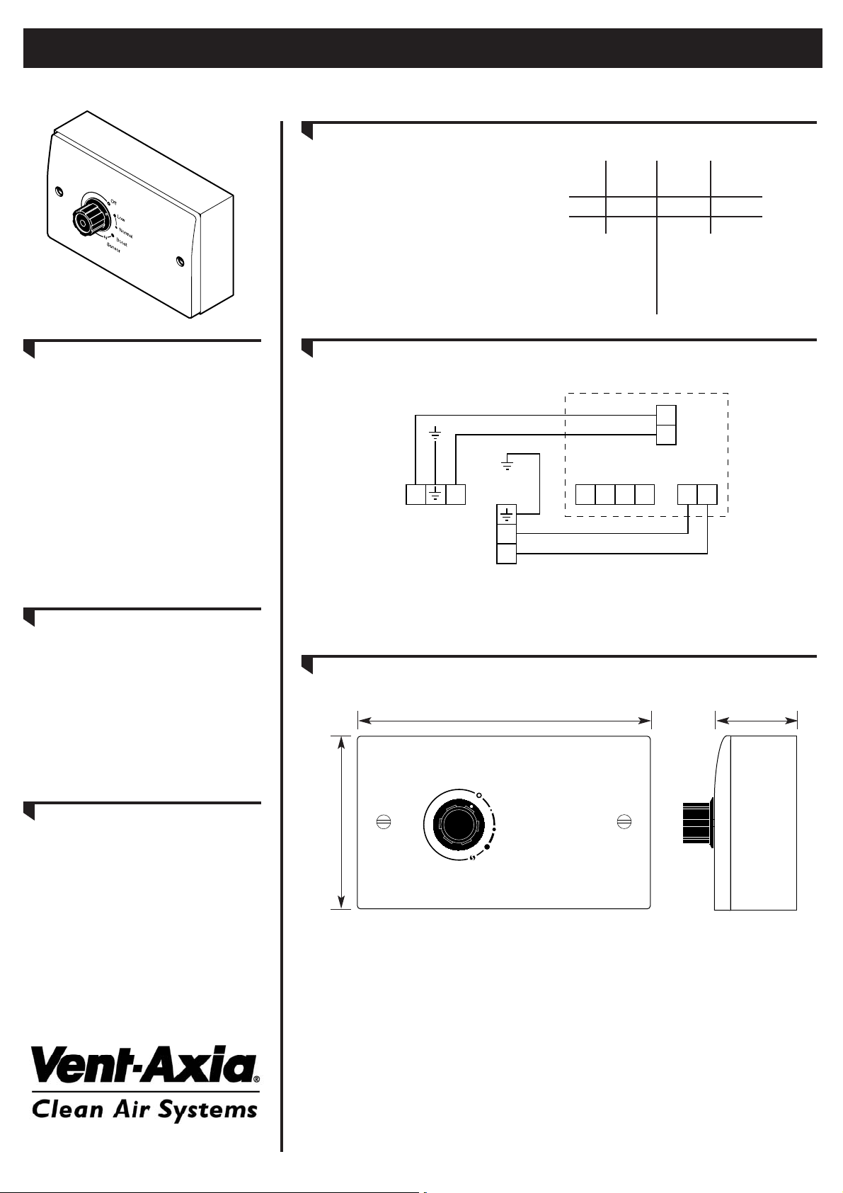
The VCON6 is designed for use with all
HR300 series units and in line mixed flow
fans type BM100, BM125 and BM150.
The VCON6 provides ON/OFF switching
and control over three speeds. The
controller also provides connection
terminals for the optional use of external
sensors/timers to provide automatic
ON/OFF control at any speed, or
switching between any two speeds as
required. The ‘sensor’ position on the
VCON6 brings this system into operation,
speed control is dependent on the wiring
option selected (see over).
INSTALLATION
The VCON6 is built on a standard single
gang plate and is designed for both
surface and flush mounting, using a
standard 25mm plastic or metal back box.
If a metal back box is used, it must be
earthed.
NOTE: The wiring should be suitably
(BASEC or HAR) approved cable of
appropriate current carrying capacity.
MULTIPLE UNIT CONTROL
The VCON6 can be used to control up to
three separate HR300 series units or up to
six mixed flow fans, type BM100, BM125,
and BM150. All multiple unit connections
must be wired in parallel.
Multiple wires must not be taken to the
controller. A junction box must be added
with a single connection taken from the
junction box to the controller. When
securing the controller to it’s back box,
care must be taken to ensure that the
P.C.B. and it’s wires do not get damaged.
VCON6 Controller
Three Speed Controller / Sensor Interface
Instruction Sheet
AIR VOLUMES (M3/HR)
All the remote units as HR300, subject to
effect of ducting layout and resultant
system resistance (pressure drop).
HR300
HR200V
HR300RW6
Boost
Normal
Low
Extract
300
210
75
Supply
270
190
70
DIMENSIONS
MANUAL
CONTROL WIRING
Low
Normal
Boost
Off
ABC
Sensor
148mm 41mm
87mm
Mains Supply
(3 amp fused)
Fan (HR300 series)
(BM100/BM125/BM150)
Terminals
L
N
N
L
VCON6
Terminals
FNSMBN LC
Page 2
VENT-AXIA LIMITED
Fleming Way, Crawley, West Sussex RH10 9YX
Tel:- 01293 526062
Fax:- 01293 551188
Internet site at:- www.vent-axia.com
AUTOMATIC
CONTROL OPTIONS
These wiring options are activated when controller is turned to ‘sensor’ position.
ON/OFF AT LOW SPEED ON/OFF AT NORMAL SPEED ON/OFF AT BOOST SPEED
LOW TO NORMAL
SPEED SWITCHING
NORMAL TO BOOST
SPEED SWITCHING
LOW TO BOOST
SPEED SWITCHING
VCON6 Terminal Block
Change Over
Switch/Sensor
B
M
S
C
VCON6 Terminal Block
Change Over
Switch/Sensor
B
M
S
C
VCON6 Terminal Block
Change Over
Switch/Sensor
B
M
S
C
AUTOMATIC CONTROL USING HUMIDITY SENSOR (REF: HS6)
These wiring options are activated when controller is turned to ‘sensor’ position. Fan units will turn ON or change speed on rise in humidity to
above the preset level. Units will revert to lower speed or turn off when humidity level falls below the preset level.
OFF/LOW SPEED ON/OFF AT NORMAL SPEED ON/OFF AT BOOST SPEED
LOW TO NORMAL
SPEED SWITCHING
NORMAL TO BOOST
SPEED SWITCHING
LOW TO BOOST
SPEED SWITCHING
VCON6 Terminal Block
HS6 Terminals
Neutral
Live
B
M
S
C
0 2 1 N L
VCON6 Terminal Block
HS6 Terminals
Neutral
Live
B
M
S
C
0 2 1 N L
VCON6 Terminal Block
HS6 Terminals
Neutral
Live
B
M
S
C
0 2 1 N L
372504C - 7/04
VCON6 Terminal Block
S
M
B
C
VCON6 Terminal Block
S
M
B
C
VCON6 Terminal Block
S
M
B
C
Sensor/External Switch
Sensor/External Switch
Sensor/External Switch
Neutral
VCON6 Terminal Block
S
M
B
C
0 2 1 N L
HS6 Terminals
Live
VCON6 Terminal Block
S
M
B
C
0 2 1 N L
HS6 Terminals
Neutral
Live
VCON6 Terminal Block
S
M
B
C
0 2 1 N L
Neutral
HS6 Terminals
Live
 Loading...