

Page 1
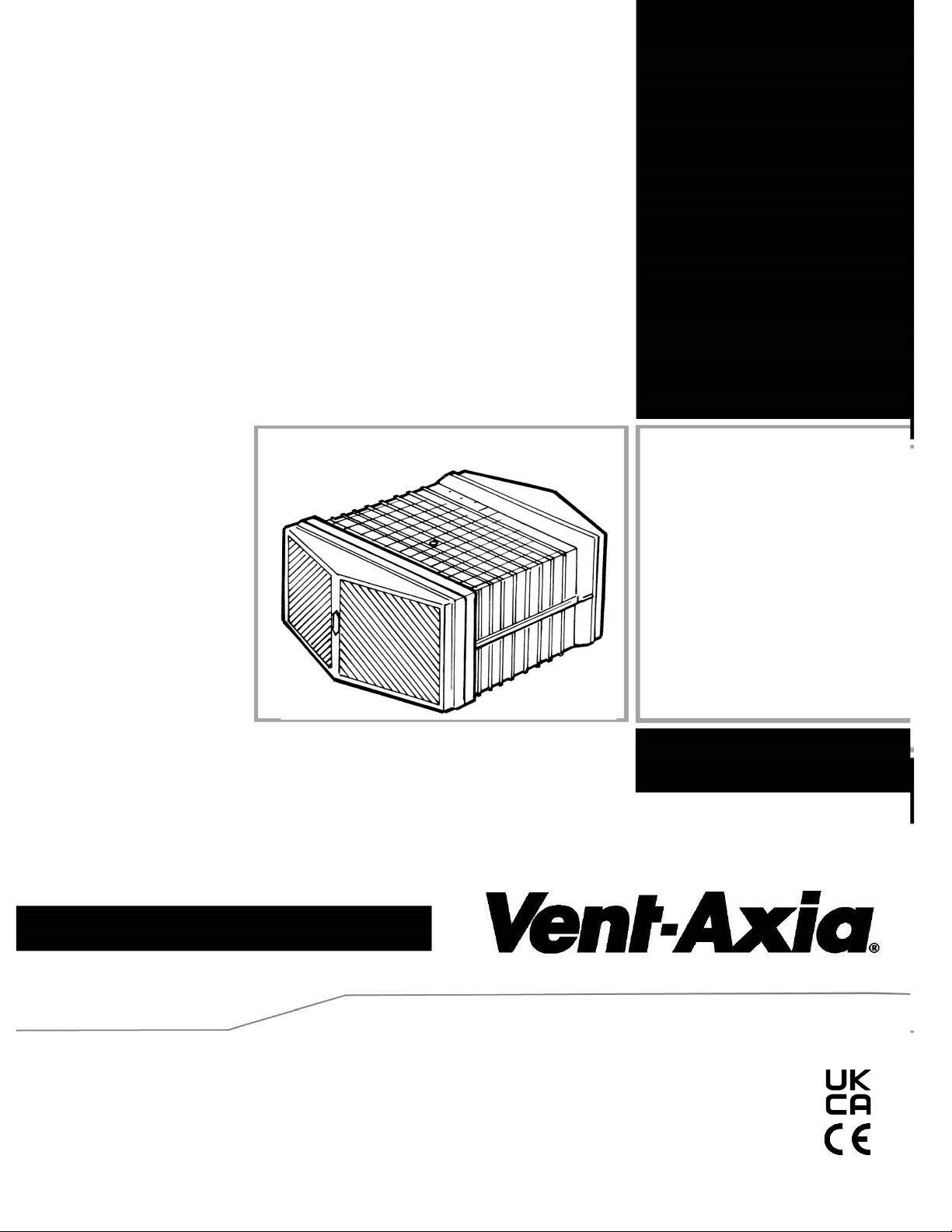
HR500 & HR500X
Wall Mounting
Heat Recovery Ventilation Units
Installation and Wiring Instructions
Stock Ref. N°
14101010B - HR500
(without shutter)
14101070 - HR500X
(with shutter)
PLEASE RETAIN THESE INSTRUCTIONS WITH THE PRODUCT.
Copyright © 2009 Vent-Axia Limited. All rights reserved.
Page 2
Warnings & Safety Information
IMPORTANT SAFETY INFORMATION
8. Young children should be supervised to
ensure that they do not play with the
appliance.
PLEASE READ THESE
INSTRUCTIONS CAREFULLY
BEFORE COMMENCING
INSTALLATION.
1. Do not install this product in areas where
the following may be present or occur:
• Excessive oil or a grease laden
atmosphere.
• Corrosive or flammable gases, liquids or
vapours.
• Subject to direct water spray from hoses.
• Ambient temperatures higher than 40°C.
• Possible obstructions that may hinder
access to or removal of the unit.
2. All wiring must be in accordance with the
current IEE wiring regulations BS7671, or
appropriate standards of your country.
Installation should be inspected and tested
by a suitably qualified person after
completion.
INSTALLATION GUIDANCE
1. The installer is responsible for the installation and
electrical connection of the system on site. It is the
responsibility of the installer to ensure that the equipment is
safely and securely installed and left only when
mechanically and electrically safe.
2. All regulations and requirements must be strictly followed
to prevent hazards to life and property, both during and
after installation, and during any subsequent servicing and
maintenance.
Disposal
This product should not be disposed of with household
waste. Please recycle where facilities exist. Check with
your local authority for recycling advice.
3. Ensure the mains supply (voltage,
frequency and phase) complies with the
rating label.
4. The power feed to the unit should be
provided with a local double pole fused spur
fitted with a 3A fuse having a contact
separation of at least 3mm.
5. This unit must be earthed.
6. Precautions must be taken to avoid the
back-flow of gases into the building from the
open flue of gas or other fuel-burning
appliances.
7. This appliance is not intended for use by
persons (including children) with reduced
physical, sensory or mental capabilities, or
lack of experience and knowledge, unless
they have been given supervision or
instruction concerning use of the appliance
by a person responsible for their safety.
HR500 and HR500X Installation & Wiring Instructions 2
Page 3
Product Description
Product Description
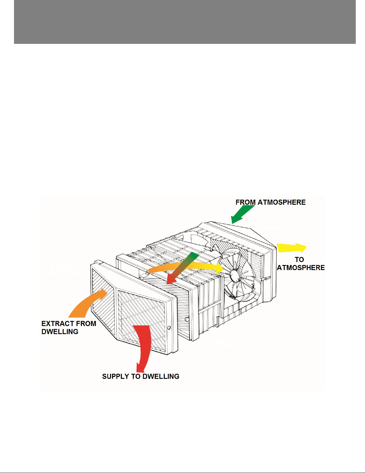
The Vent-Axia HR500 and HR500X are heat recovery units for through the wall installation, which extract stale
air and as it does so, a heat exchanger within the unit transfers up to 70% of the heat to the freshing incoming
air.
The unit is ideal for computer rooms, classrooms, offices and the health and leisure industries, the perfect
solution for commercial areas that require a high performance balanced intake/extract ventilation scheme.
Air Direction
HR500 and HR500X Installation & Wiring Instructions 3
Page 4
Product Description
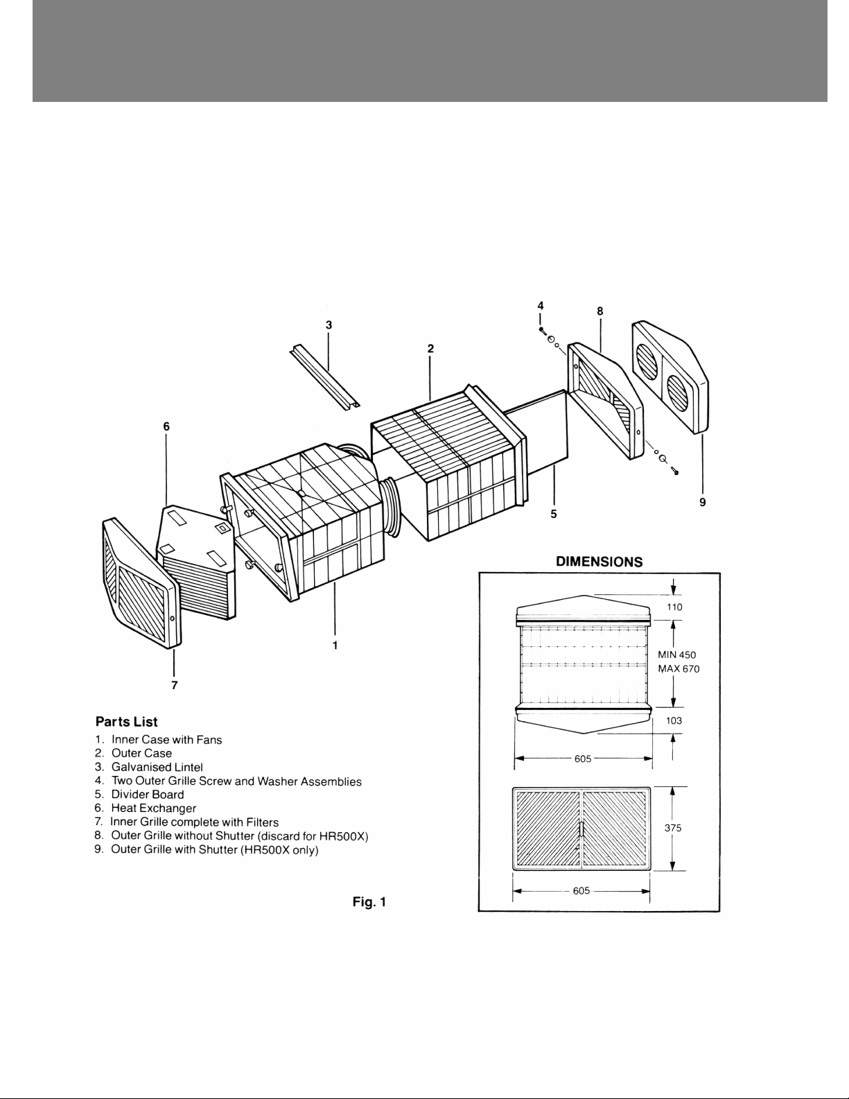
Exploded View of Fan Unit and Dimensions
HR500 and HR500X Installation & Wiring Instructions 4
Page 5

Installation
Overview
Installation should only be carried out by a qualified electrician and installer.
Before Installation of the Unit
Inspect the Unit
When taking delivery of the unit, check the items delivered against the enclosed delivery note. Inspect the unit
for damage in transit. If in doubt, contact Customer Services. Each box contains an HR500 unit and an
accessory pack, energy rating labels and product documentation.
Unit Installation
The HR500 and HR500X units are typically installed through the wall.
The wall should have sufficient strength to support the unit.
Take into consideration the position of the electrical services.
Ensure there is an adequate access for installation, operation and maintenance.
It is recommended that a local isolation switch is installed within 1m of the unit to facilitate future maintenance.
HR500 and HR500X Installation & Wiring Instructions 5
Page 6
Installation
Installation
1. Check the components supplied against the parts list
(see Fig. 1).
2. Before deciding on the final position of the unit, check
that there are no buried cables, pipes or obstructions
on the outside wall.
3. Working from the inside, mark out the position of the
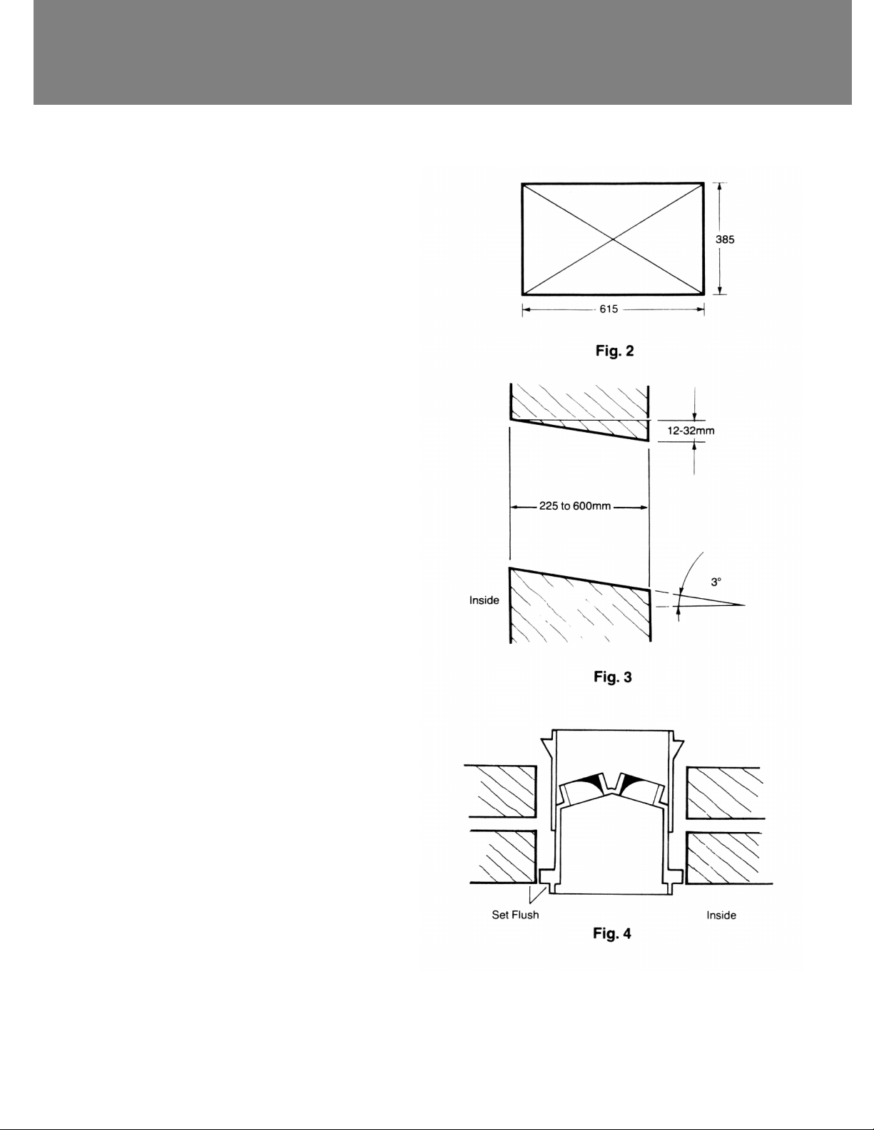
hole to be cut 615mm wide x 385mm high. Mark the
centre point by drawing diagonals (see Fig. 2).
4. Drill horizontally through the wall at the marked centre
point using a long reach drill.
5. Estimate the wall thickness and mark the position of
the hole to be cut in the outer wall using the centre
hole as a guide. Hole size 615mm wide x 385mm high.
Note: Outer hole should be marked 12mm to 32mm
(225mm wall to 600mm wall) lower than inner hole
so as to produce a 3 degree slope toward the
outside (see Fig. 3).
6. Carefully cut the holes in the inner and outer leaves to
form a suitable aperture to receive the unit.
Note: Bricks will cut more easily and accurately if a
series of holes are drilled close together along the
marked lines.
7. Remove the inner and outer grilles. While the inner
grille is released by depressing the buttons projecting
through its side walls, the outer grille is released by
removing the screw and washer assemblies passing
through the side walls.
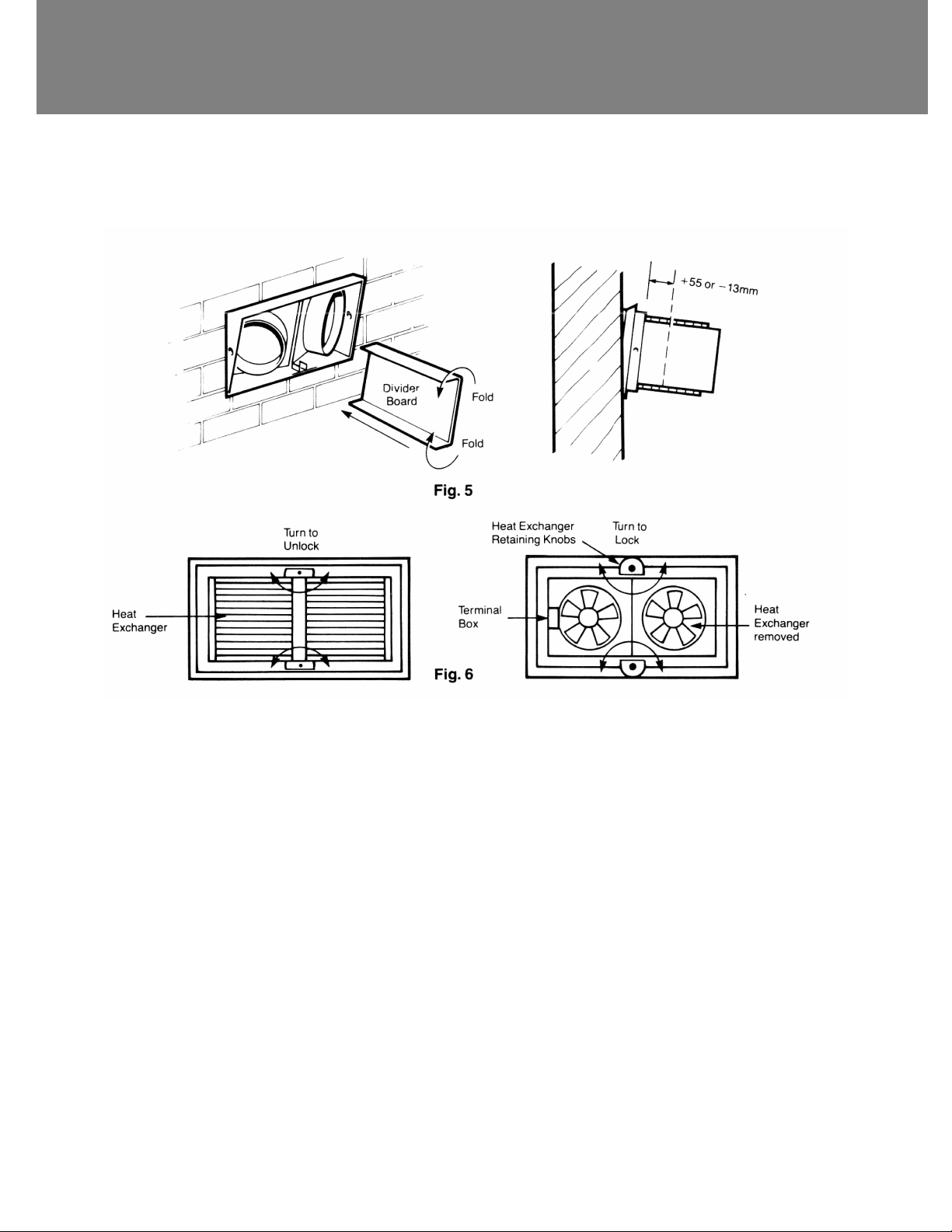
8. After turning the heat exchanger retaining knobs to
the unlocked position, withdraw the heat exchanger
(see Fig.6).
Note: The heat exchanger should be handled by the
grey top and bottom plates and frame only. Care
should be taken so as not to damage the element.
9. Try the casing assembly in the wall and ensure that
the shoulder on the inner case can be set flush with
the internal wall surface (see Fig.4).
10. Choose the site for controller or switch box and run a
suitable length of 5-core 0.75mm2 cable and it must
be round with a diameter of between 7 and 10 mm to
suit the supply cable gland (i.e. the largest gland) in
the terminal box.
HR500 and HR500X Installation & Wiring Instructions 6
Page 7
Installation
11. Position the unit in the wall aperture with the galvanised lintel placed on top of the ribs on the case to provide support for
the outer wall. Thread the cable from the controller between the inner and outer cases and through the hole located on the
left side of the top face of the inner case.
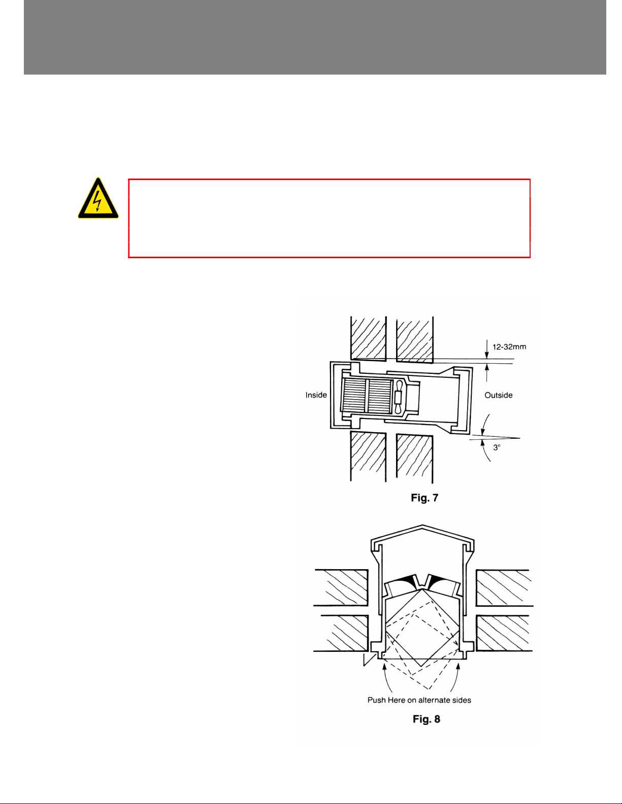
12. Position the shoulder of the inner case flush with the interior wall surface (see Fig. 4). This will automatically result in the
designed 3 degree slope to outside. If necessary, extend the telescopic outer case so that the lower shoulder of the outer
case is flush with or proud of the outer wall surface (see Fig. 7).
13. Make good around the inner and outer cases. If firmer fixings are required, secure the inner and outer cases in place by
plugging and screwing into the wall leaves.
CAUTION – Care should be taken not to distort either inner or outer cases when fixing and making good.
14. Working from outside, position the divider board in the channel between the fan housings by folding the edges down. Cut
the board such that it extends beyond the end of the outer case by 55mm for the HR500 type and falls short of the end of
the outer case by 13mm for the HR500X type (see Fig.5). Replace the outer grille and retain it with the screw and washer
assemblies previously removed. Before replacing and fixing the outer shuttered grille on the HR500X type pass the cable
from the grille through the hole with a grommet in the right hand end face of the inner case.
HR500 and HR500X Installation & Wiring Instructions 7
Page 8
Installation
15. Internal wiring connections.
1. MAINS SUPPLY VOLTAGES (220-240 V AC) ARE PRESENT IN THIS EQUIPMENT, WHICH MAY CAUSE
DEATH OR SERIOUS INJURY BY ELECTRIC SHOCK. ONLY A QUALIFIED ELECTRICIAN OR INSTALLER
SHOULD CONNECT THE POWER SUPPLY TO THIS UNIT. MAINS SUPPLY MUST BE ISOLATED BEFORE
MAKING CONNECTION.
2. THIS UNIT MUST BE CORRECTLY EARTHED.
Pass the supply cable through the largest cable
gland in the side of the terminal box. For the
HR500X the cable from the shuttered grille passes
through the remaining free cable gland. Cut the
cables to the minimum length required and make the
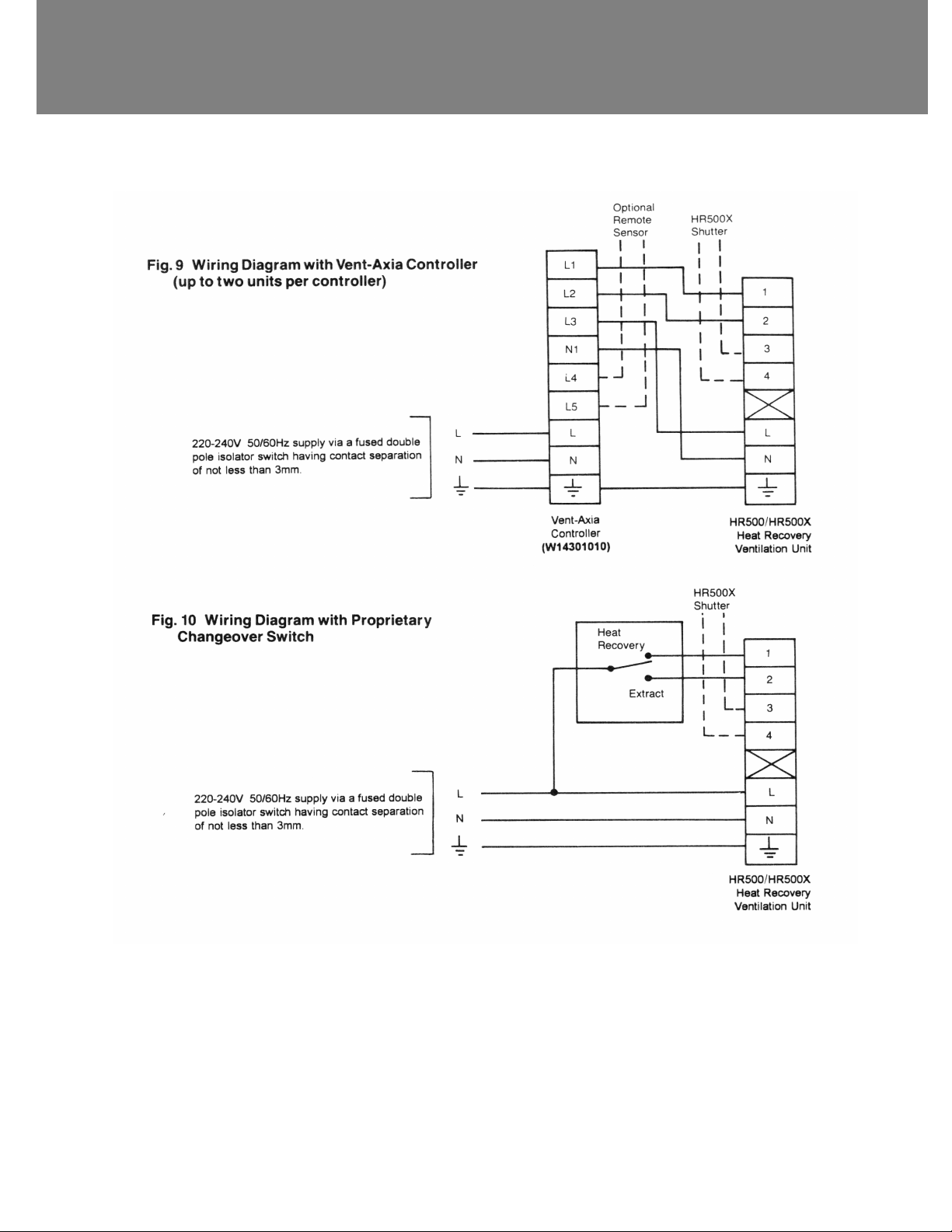
internal wiring connections within the terminal box
(see Fig.6). Connect the supply cable from VentAxia Controller to the appropriate terminals of the
terminal block within the terminal box as shown in
Fig. 9. If a Vent-Axia Controller is not used, connect
the supply cable as shown in Fig. 10. Ensure all
cable glands are tightened sufficiently to seal onto
the cables.
16. Fit the heat exchanger into the casing of the unit.
Pressing lightly on alternative side legs, ‘’walk’’ the
heat exchanger firmly into place (see Fig. 8).
17. Fix the inner grille to the casing by depressing the
button on each side and sliding the grille over them
so that they locate in the corresponding holes in the
grille sides. Ensure that the buttons are positioned on
their fixing screws so that the seal on the inner edge
of the grille is pressed against the mating face on the
inner case to give an airtight seal.
18. Connect to the mains and turn the power on.
19. Switch on at the controller and select the speed and
function required – see operating instructions
supplied with the controller.
WARNINGS
HR500 and HR500X Installation & Wiring Instructions 8
Page 9
Installation
HR500 and HR500X Installation & Wiring Instructions 9
Page 10
Maintenance
WARNING
THE FAN AND ANCILLARY CONTROL EQUIPMENT MUST BE ISOLATED FROM THE POWER SUPPLY
DURING MAINTENANCE.
Maintenance
Heat recovery units require regular maintenance. The HR500 and HR500X has been designed to facilitate access to enable
maintenance to be carried out easily. The actions below should be carried out at least every 6-months as conditions dictate.
Item Action
Unit & Heat Exchanger
Cell
Motors Inspect the motors for build-up of dust and dirt on the impeller blades, which could cause
Fastenings Check that all unit and wall-mount fastenings are sufficiently tight and have not become
Inspect and clean the unit
1. Isolate the mains power supply.
2. Remove front cover from the unit.
3. Slide out the heat exchanger.
4. Wash the outer cover and heat exchanger in warm water using a mild detergent (such as
Milton Fluid) and dry thoroughly.
NOTE: Keep water away from all electrical components and wiring within the unit.
imbalance and increased noise levels. Vacuum or clean if necessary.
loose. Re-tighten if necessary.
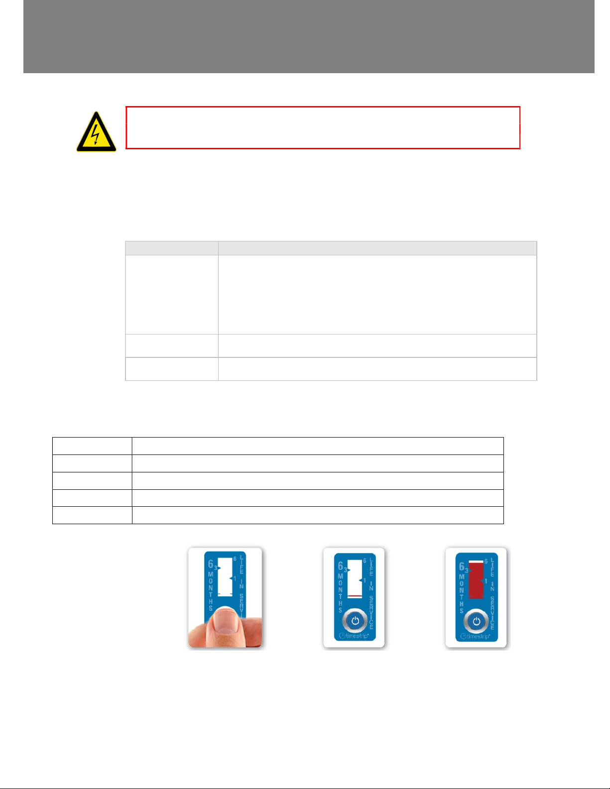
The unit is supplied with four, 6-month Timestrip indicators. A Timestrip is a single use self-adhesive label that once activated will turn
red over 6 months. It should be used to keep track of when the filter and cell need cleaning/replacement. Using the self-adhesive
backing the strip can stuck near the units controls, or in a easily visible place.
A normal cleaning schedule for a unit would be as follows:
After installation Activate the 1st Timestrip
After 6 months Clean cell, clean filter, activate 2nd Timestrip
After 12 months Clean cell, clean filter, activate 3rd Timestrip
After 18 months Clean cell, clean filter, activate 4th Timestrip
After 24 months
Note: The above is the minimum requirement; more frequent cleaning intervals may be needed depending on the environment the unit
is installed in.
Activating the Timestrip.
Clean cell, replace filters, the new filters will be supplied with 4 additional Timestrip indicators
1. Activation: Fully squeeze the activation button between thumb and finger. A red line will appear within 1-2 minutes to show that the
Timestrip has been activated.
2. Peel off the backing liner and stick the Timestrip to the Unit or near the controls of the unit. The location should make it obvious to the
person responsible for maintenance that the unit needs attention.
HR500 and HR500X Installation & Wiring Instructions 10
Page 11
Product FICHE
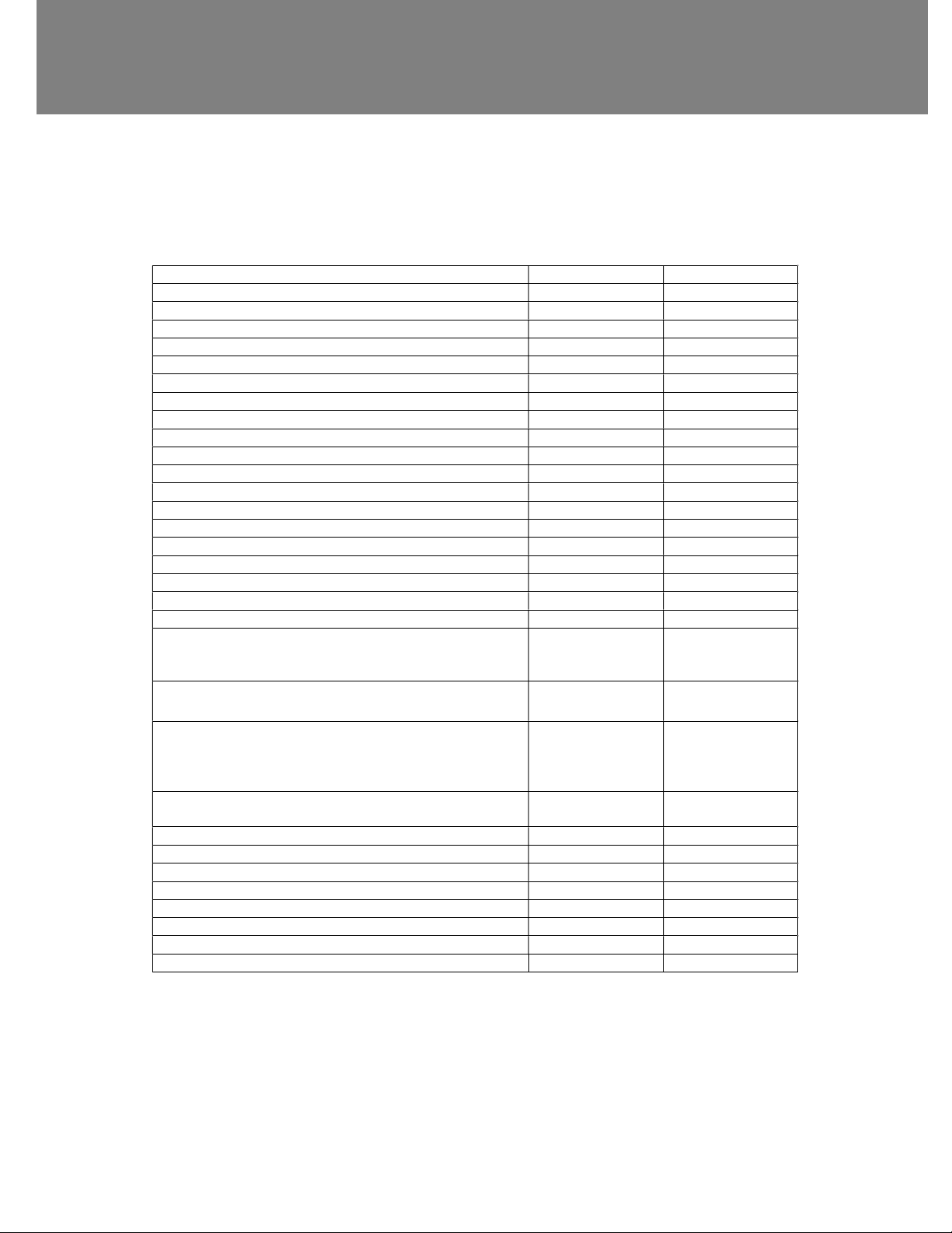
PRODUCT FICHE
For Residential Ventilation Units (Complying Commission Delegated Regulation (EU) No 1254/2014)
Name: Vent-Axia Vent-Axia
Model ID (Stock Ref.) : HR500 – 14101010B HR500 X - 14101070
SEC Class D E
SEC Value ('Average') -20.17 -18.39
SEC Value ('Warm') 0.46 2.25
SEC Value ('Cold') -56.98 -55.20
Label Required? (Yes/No=Out of scope) Yes Yes
Declared as: RVU or NRVU/UVU or BVU RVU/BVU RVU/BVU
Speed Drive Variable Speed Variable Speed
Type HRS (Recuperative, Regenerative, None) Recuperative Recuperative
Thermal Eff: [ (%), NA(if none)] 70.00 70.00
Max. Flow Rate (m3/h) 550.80 550.80
Max. Power Input (W): (@Max.Flow Rate) 210.00 220.00
LWA: Sound Power Level (dB) 70.52 70.52
Ref. Flow Rate (m3/s) 0.10710 0.10710
Ref. Pressure Diff. (Pa) 70.00 70.00
SPI [W/(m3/h)] 0.52 0.57
Control Factor & Control Typology: (CTRL/ Typology)
Control Factor; CTRL 1.00 1.00
Control Typology Manual Control Manual Control
Declared: -Max Internal & External Leakage Rates(%) for BVUs or carry over
(for regenerative heat exchangers only),
-&Ext. Leakage Rates (%) for Ducted UVUs;
Mixing Rate of Non-Ducted BVUs not intended to be equipped with one
duct connection on either supply or extract air side;
<5% Internal, <5%
External
TBC TBC
<5% Internal, <5%
External
Position and description of visual filter warning for RVUs intended for use
with filters, including text pointing out the importance of regular filter
changes for performance and energy efficiency of the unit
For UVUs (Instructions Install Regulated Supply/Extract Grilles Façade) N/A N/A
Internet Address (for Disassembly Instructions) www.vent-axia.com www.vent-axia.com
Sensitivity p. Variation@+20/-20 Pa: (for Non-Ducted VUs) TBC TBC
Air Tightness-ID/OD-(m3/h) (for Non-Ducted VUs) TBC TBC
Annual Electricity Consumption: AEC (kWh/a) 7.60 8.31
Annual Heating Saved: AHS (kWh/a)
AHS: Average 38.49 38.49
AHS: Warm 17.41 17.41
AHS: Cold 75.30 75.30
N/A N/A
HR500 and HR500X Installation & Wiring Instructions 11
Page 12
Guarantee and Contact information
The Guarantee
Vent-Axia guarantees its products for two years from date of purchase against faulty material or workmanship. In the event of any part being found
to be defective, the product will be repaired, or at the Company’s option replaced, without charge, provided that the product:
Has been installed and used in accordance with the instructions given with each unit.
Has not been connected to an unsuitable electricity supply. (The correct electricity supply voltage is shown on the product rating label
attached to the unit).
Has not been subjected to misuse, neglect or damage.
Has not been modified or repaired by any person not authorised by the company.
Please return the complete product, carriage paid to your original supplier or nearest Vent-Axia Centre, by post or personal visit.
Please ensure that it is adequately packed and accompanied by a letter clearly marked “Guarantee Claim” stating the nature of the fault and
Head Office: Fleming Way, Crawley, West Sussex, RH10 9YX.
EU Authorised Representative: Vent-Axia Bedrijvenweg 17 7442 CX Nijverdal Nederland
[email protected]
UK NATIONAL CALL CENTRE, Newton Road, Crawley, West Sussex, RH10 9JA
SALES ENQUIRIES: Tel: 0344 8560590 Fax: 01293 565169
TECHNICAL SUPPORT Tel: 0344 8560594 Fax: 01293 532814
For details of the warranty and returns procedure please refer to www.vent-axia or write to Vent-Axia Ltd, Fleming Way, Crawley, RH10 9YX
469539J © 2017 Vent-Axia Limited. All rights reserved. 0621
Applicable only to products installed and used in the United Kingdom.
For details of guarantee outside the United Kingdom contact your local supplier.
IF CLAIMING UNDER TERMS OF GUARANTEE
providing evidence of date and source of purchase.
The guarantee is offered to you as an extra benefit, and does not affect your legal rights
HR500 and HR500X Installation & Wiring Instructions 12
 Loading...