

Ventamatic NXMD1WH User Manual
Designer Light for use with Bath Fan
INSTALLATION INSTRUCTIONS
The NuVent Designer Light for use with Bath Fan listed in these
instructions is designed for use as a fan-light in the bathroom with
any pre-installed NuVent MR or MS Series fan-light (all of which
use the M2000 Universal Housing™). The NuVent Designer Light
may also be used as a separate light fixture.
SAFETY INSTRUCTIONS WARNING: TO REDUCE THE
RISK OF FIRE, ELECTRIC SHOCK OR INJURY TO
PERSONS OBSERVE THE FOLLOWING:
1. Use this unit only in the manner intended by the manufacturer.
If you have questions, contact the manufacturer.
2. Before servicing or cleaning unit, switch power off at service
panel and lock the service disconnecting means to prevent power
from being switched on accidentally. When the service disconnecting
means cannot be locked, securely fasten a prominent warning
device, such as a tag, to the service panel.
3. Installation work and electrical wiring must be done by qualified
person(s) in accordance with all applicable codes and standards,
including fire-rated construction and standards. Turn OFF power
and lock out service panel before installing or wiring this product. If
you are unfamiliar with methods of installing electrical wiring, secure
the services of a qualified electrician.
4. Sufficient air is needed for proper combustion and exhausting of
gases through the flue (chimney) of fuel burning equipment to
prevent backdrafting. Follow the heating equipment manufacturer's
guideline and safety standards such as those published by the
National Fire Protection Association (NFPA) and the American
Society of Heating, Refrigeration and Air Conditioning Engineers
(ASHRAE) and the local code authorities.
5. When cutting or drilling into wall or ceiling, do not damage
electrical wiring and other hidden utilities.
6. Ducted fans must always be vented to the outdoors.
7. NEVER place a switch where it can be reached from a tub or
shower.
8. This unit must be grounded.
9. This unit is UL listed. Type I.C. inherently protected.
10. This fan is not for use in kitchens.
11. Acceptable for use over a bathtub or shower when installed in a
GFCI protected circuit.
12. Install fan at least 1.5m (5 feet) above the floor.
CAUTION: FOR GENERAL VENTILATING USE ONLY!
1. Do not use to exhaust hazardous or explosive materials and
vapors.
2. This product is designed for installation in flat ceilings only. Do
not mount this product in a wall.
3. The light fixture assembly must be mounted to the NuVent
M2000 housing or to a wiring outlet box.
Models:
NXMD1AB
NXMD1OB
NXMD1WH
TOOLS REQUIRED FOR INSTALLATION
• Screwdriver
• Electric drill
• 1/8" drill bit
• Wire cutters
• Wire stripper
• UL approved wire nuts/connectors
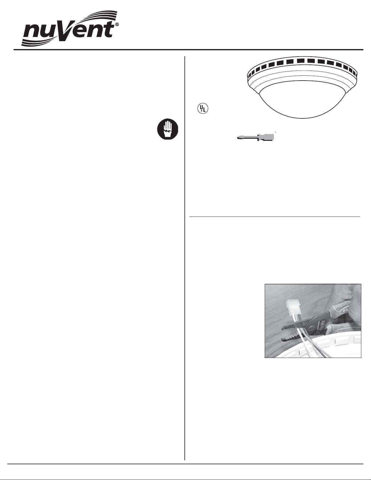
PARTS LIST:
1 Designer Light frame
1 Glass dome
1 Mounting bracket
2 2
1/2" Philips pan head screws
4 1/2" Philips pan head screws
Note: Not all of these parts will
be used in these installations. If
you are missing parts, please
phone 800.433.1626 and ask for
Customer Service.
INSTALLATION INSTRUCTIONS
FOR USE AS A SEPARATE LIGHT FIXTURE
WIRING: This product requires 120v AC standard house wiring (with
ground) from the power source through a standard wall switch. Turn
OFF power and lock out service panel before installing or wiring this
product. If you are unfamiliar with methods of installing electrical
wiring, secure the services of a qualified electrician.
1. The NuVent Designer
Light has a pre-installed
quick connector that will not
be used when the Designer
Light is used as a separate
light fixture. Before
beginning installation, the
quick connector must be
removed. (IMPORTANT!
Do not cut these wires if you
intend to use the designer
light with a fan. For that use,
follow instructions on the
reverse side of this page.) Using a wire cutter, cut each of the three
wires (white, black, and green) next to the quick connector. (See Figure 1).
2. Remove the ground wire (green) from the Designer Light frame by
removing the grounding screw. Store screw safely until needed in
Step 4 below.
3. Using a wire stripper, remove approximately 1/2" of insulation
from the black and white wires on the Designer Light.
4. Connect the supply wiring to the designer light wiring using UL
approved connectors: black to black and white to white. Connect
ground wire from the supply to the Designer Light frame using
grounding screw removed in Step 2.
5. Mount Designer Light frame to ceiling box using the two mounting
screws provided.
FIGURE 1
NuVent is the Bath and Kitchen Ventilation product line from Ventamatic, Ltd., 100 Washington St, Mineral Wells, TX 76067 (Phone: 800.433.1626 Fax: 940.325.9311)
INSTALLATION INSTRUCTIONS FOR USE WITH BATH FAN
The NuVent Designer Light (Models NXMD1AB, NXMD1OB, and
NXMD1WH) is designed to be used with any pre-installed NuVent MR
or MS Series fan-light (all of which use the M2000 Universal Housing™).
(For installation as a separate light fixture see previous page.)
1. The NuVent Designer Light frame has a pre-installed center bolt
that will not be used in this installation. Remove.
2. Remove the grille from the pre-installed NuVent fan-light.
Note: On units manufactured prior to 2005, the grille is mounted to
the housing with torsion springs; on units manufactured during or
after 2005, the grille/light assembly is mounted to the housing with a
hex screw.
3. Unplug the light assembly quick connector. (See Figure 1.)
FIGURE 1
6. Place the motor plate on a bench or other flat surface. Center the
mounting bracket (provided) on the motor plate (See Figure 4A).
Using the four pre-drilled holes in the mounting bracket as a template
(Figure 4B), mark on the motor plate the position of the holes.
Remove the mounting bracket. Drill the four marked holes in the
motor plate using a 1/8" drill bit.
FIGURE 4
{
4B
4A
{
4B
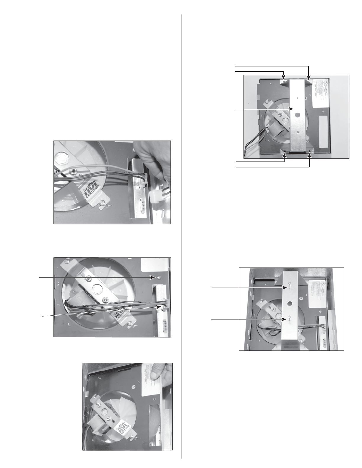
7. Attach the mounting bracket to the motor plate with four 1/2"
pan head screws (provided).
4. Remove the motor plate screw (Figure 2A). Store screw safely until
needed in Step 8. Remove the motor quick connector (Figure 2B).
FIGURE 2
2A
2B
5. Slide the motor plate out of the housing as indicated in Figure 3.
FIGURE 3
8. Reinsert the motor plate in the housing and secure motor plate
with motor plate screw removed in Step 4.
9. Reinsert the motor quick connector.
10. Insert the two 2" Phillips pan head screws (provided) in the
mounting bracket. See Figure 5.
FIGURE 5
11. Insert the quick connector on the Designer Light frame into the
same receptacle in the pre-installed housing from which the old light
assembly was disconnected in Step 3.
12. Position the keyhole slots in the Designer Light frame over the
two screws in the mounting bracket. Twist in place and secure
Designer Light frame by tightening screws in mounting bracket.
13. Insert two 60W incandescent bulbs or two compact fluorescent
bulbs into light sockets.
14. Install glass dome. Twist slightly to secure.
 Loading...