

Ventair Z564EXTSS, Z483EXTSS, Z524EXTSS Installation Manual
CEILING FAN INSTALLATION MANUAL
CAUTION
READ INSTRUCTIONS CAREFULLY FOR SAFE INSTALLATION
AND FAN OPERATION
INSTALLATION
OPERATION
MAINTENANCE
(This photo is for reference only, it doesn’t mean you are purchasing identical products. Fan picture is for
illustration purpose only, styles may vary according to the particular models)
Model No. : Z524EXTSS/Z564EXTSS/Z483EXTSS

CON GRAT ULATIONS , as you ha ve jus t c hos en a quality ceili ng fan .
Thi s fan is Fu ll 316 Stain les s S tee l a nd is an ou tdoor fan su ita ble fo r M ari ne/ Co astal /
Tr opi cal Areas etc.
C O N G R A T U L A T I O N S O N Y O U R CH O I C E
The i nfo rmation c ont ain ed in th e foll owi ng pages ha s been p rep ared t o ensure yo u of
trouble-f ree operation of your Cei ling F an .
1. To ens ure the su cces s o f t he inst alla tion be su re to read th e i nstr ucti ons and st udy the
dia gram s t horo ughl y.
2. All elec tric al work sh o uld onl y c omme nce aft er disc onne ctio n o f t he powe r b y
rem ovin g f uses or tu rnin g o ff the cir cuit br eake r t o e nsur e a ll pole is olat ion of the
ele ctri cal sup ply.
3. Mak e s ure tha t y our ins t all a tion si te will no t a llow th e r otat ing fan bl ades to co me into
con tact wi th any obj ect and tha t t here is a min imum cl eara nce of 150 mm (6") fr om the
bla de tip to the wa ll o r c eili ng. Ple ase not e t hat the bi gger th is clea ranc e i s t he bett er the
air flow fr om your fa n w i ll be. Ens ure the bl ades ar e m ount ed at a u nits he ight of 2. 1
met ers fro m t he floo r w hen the fan is in stal led.
4. The fi xing po int for th e f an must be ab le to supp ort the we ight of 6 tim es that of th e n et
wei ght of the fa n. Net wei g hts can be fo und on the bo ttom of th e u nit box . I f y ou are
mou ntin g t he fan to a ceil i ng junc tion bo x, the box an d f ixin g m ust be abl e t o s uppo rt the
mov ing wei ght of the fa n a n d m ust not tw ist or wor k l oose .
5. The fa n m ust be ear thed .
6. Do not co nnec t t he fan mot o r t o a di mmer sw itch . This ma y g ive an uns atis fact ory
per form ance (m otor hu m ) a nd caus e d amag e t o t he moto r.
7. It is not re comm ende d t h at ceil ing fan s a nd gas app lian ces be ope rate d i n t he same
roo m a t t he same ti me.
8. The fa n m ust be tur ned off a nd stop ped com plet ely bef ore rev e rsin g t he fan dir ecti on.
Thi s w ill pre vent an y d a mage to th e m otor of th e u nit or con trol ler (if in stal led) .
9. Do not in sert an ythi ng i nto the fa n b lade s w hile th e f an is oper atin g. Thi s w ill dam age
the bla des and up set the bal ance of th e u nit cau sing th e u nit to wob ble.
10. Afte r t he fan is com plet e ly inst alle d m ake sur e t hat all co nnec tion s a re secu red and
tigh tene d t o p reve nt a ny prob lems .
11. Beca use of the fa ns natu ral mov emen t, some co nnec tion s m ay loos en. Che ck the
sup port co nnec tion s, b rac k ets and bl ade att achm ents tw ice a year to ma ke sure th ey are
all se cure d. If they ar e l o ose, ti ghte n w ith a scre wdri ver.
.
.
S A F E T Y P R E C A U T I O N S
1

Your warra n t y w i l l b e vo i d if a solid- s tate dimme r typ e fa n con t roller
or o ther brand wal l con t roller is used. Wit h the s e co n trolle r s t h e re
is a st r ong p ossib i l ity that the ceilin g fa n mot o r w i l l p r o duce an
unple a sant load hummi n g n o i se.
FA N
CONTRO L
FA N
INSTALLATI O N
Under our warran t y te r m s t h i s ce i l ing f an m u st b e inst a lled b y a
licen c ed e l e ctric i a n. F a ns t h a t ar e not inst a l led c o rrect l y ca n be
dange r ous, e xpens i v e to repa i r , an d voi d the warra n t y. Mo u nting
where the fan i s su b j ect t o w a t er o r moi s t ure c an b e dang e rous
and i n t u r n vo i d th e warr a nty.
FAU LT
F INDER
WARNI N G
MECHANICAL NOISE M AY BE NOTICED ON IN STAL LATI ON. ALL OW
AT LEAST 8 HO URS S ETT LIN G IN PER IOD . SOM E FA NS WOBBLE
MORE THAN OTH ERS( EVE N IN THE S AME MODE L), Y OU SHO ULD
NOT INTERPR ET THI S AS A FAU LT.
This appl i a nce is n o t i n tended for use by p erson s (in c luding
child r en) w ith reduce d ph y s ical, sens o r y o r me n t al c apabil i ties,
or l ack of e x perie n c e a n d k n o wledg e , un l e ss t hey h ave been
given sup e r visio n or inst r u ction conc e r ning use of t he a p plian c e
by a pe r son r espon s i ble for t heir safet y.
Young chil d r en s h ould be s uperv i s ed t o e n s ure that they do n ot p l ay
with the appli a nce. The impor t ant s afegu a r ds a nd i n struc t i ons
appea r ing i n t h is m a nual are not meant to c over all possi b l e
condi t ions and situat i ons t hat may o ccur. I t mu s t b e und e r stood that
commo n se n s e, c aution and care are fact o rs, w hich canno t be buil t
into any produ c t. T hese facto r s m u s t b e su p p lied by t he p erson( s )
carin g fo r and ope r a ting the unit.
I M P O R T A N T N O T E S
NOTE: ALL POLE DISCONNECTION SWITCH MUST BE INCLUDED IN
THE FIXED WIRING. A SAFETY SWITCH IN THE SWITCH BOARD TO
THE FANS’ WIRING CIRCUIT IS CONSIDERED TO COMPLY WITH
THIS REQUIREMENT.
Alwa y s ch e ck t he“ Tr o uble S hoot i n g C h eckli s t”in c luded i n t his
b o oklet b e fore call i ng f o r s e rvice . Un n ecessa r y c a lls are
i nconve n ient for all and can attra c t a Ser v i ce c harge .
2
3
I N S T A L L A T I O N I N S T R U C T I O N S
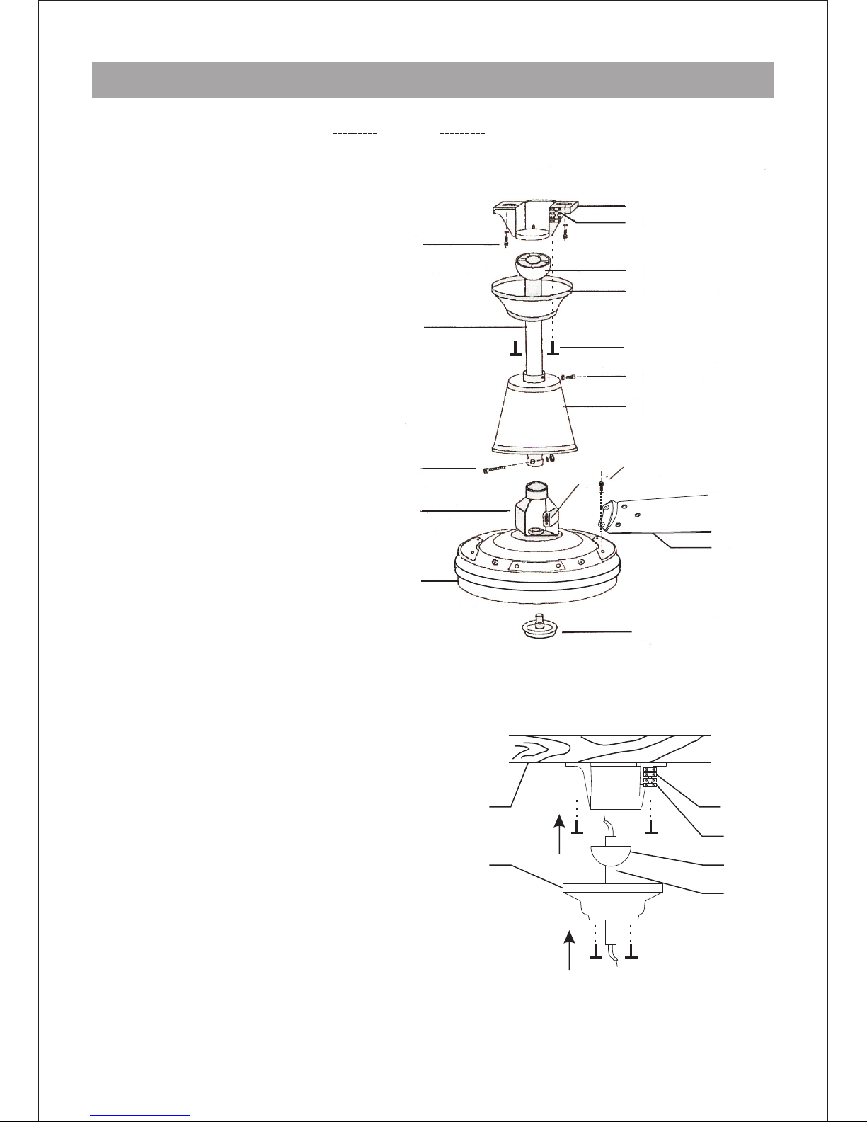
Pa rt List
1. Mount ing Bracket
2. Terminal Block
3. Hange r Ball
4. Upper C anopy
5. Screw s Fixing Canopy And
Mounting B racket
6. Screw s Fixing Mounting Bracket
And Cei ling.
7. Downr od
8. Screw F ixing Lower Canopy And
Downro d
9. Lower C anopy
10. Scre ws Fixing Blade To Mot or
11. Reverse Switch
12. Scre ws And Nuts Fixing Downrod
To The Switch Bracket
13. Blad e
14. Swit ch B racket
15. Moto r
16. Deco rative Knob
1
2
5
3
4
8
9
10
11
15
16
13
14
12
7
6
Mounti ng Bracket
Termin al Block
Hanger B all
Upper Ca nopy
Screws F ixing Canopy And
Mounti ng Bracket
Screws F ixing Mounting Bracket
And Ceil ing.
Downro d
Screw Fi xing Lower Canopy And
Downro d
Lower Ca nopy
Screws F ixing Blade To Motor
Revers e Switch
Screws And Nuts Fixing Downrod
To The Switch Bracket
Blade
Switch B racket
Motor
Decora ti ve Knob
Mounti ng Plate Hanging System
1. Ceil i ng Joist
2. Cano p y
3. Ter m inal Blo ck a nd Mount ing Plat e
4. Eart h Wi re
5. Hang e r B all
6. Down r od
Mino r des i g n c h a nges or o therw i s e m a y r e s ult i n
slig h t va r i ation bet w e e n t h e p r o duct illu s t rated
and t hat, whic h is cont a i ned w ithi n thi s pac k a ge.
1 3
4
6
2 5
I N S T A L L A T I O N I N S T R U C T I O N S
1 . O B TAI N A SU I TA B L E P O S I T I O N F O R I N S TAL L A T I O N O F YO U R C E I L I N G FA N
CAUT ION: Bef o re inst a llin g yo ur f an, make su r e y ou h ave turn ed O FF the elec t rici ty.
If i t i s ne c essary to redu c e th e le n g th o f t h e d o w nrod, ple a s e e n sure that the cut is m ade
clea n and squ a r e, t hat all b urrs are remov e d a n d th e lo c a ting hole is drill e d tr u e a n d
squa r e . I f th i s ho l e i s dr i l led out o f s q uare, you will intr o duce out of b alanc e
char a c teris t i cs t o t h e f a n , w h ich i s n o t c o vered by warra n t y.
Choo s e a loca t i on f or m ountin g th e fan whe r e t h e bl a de w i ll h ave at l e ast 2.1m of
clea r a nce from all objec t s . I f th e loc a tion you have chos e n do e s n o t ha v e a sui t a ble
supp o r t b e am, i nstal l a 2 x 4”bra c e b e t ween the ceili n g j o i sts as a su p p ort mediu m .
The brace bet w e en t he c eiling joi s t s m u st b e s t r ong enough to supp o r t a 30- 3 5 kg w eight .
2 . M O U N T I N G T H E B R A C K E T
Secure the mounti n g bra c k e t t o cei l i n g w i t h th e two screw s prov i d e d.
4
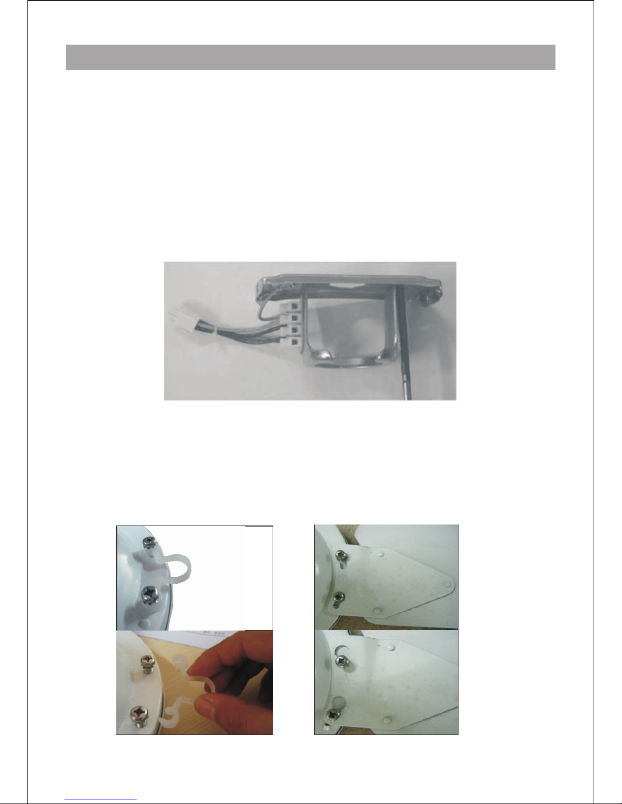
3. CONNECTING BLADE SETS TO MOTOR
Quick Fix
Take away the plastic film and put the blade holder over the screw pre assembled on the motor, and
tighten the screws. Repeat the procedure for remaining blades.
 Loading...