

Ventair HARMONY II Series, HAR1204 Series, HAR1204-L Series, HAR1204WH, HAR1204WH-L Instruction Manual
...
INSTRUCTION MANUAL
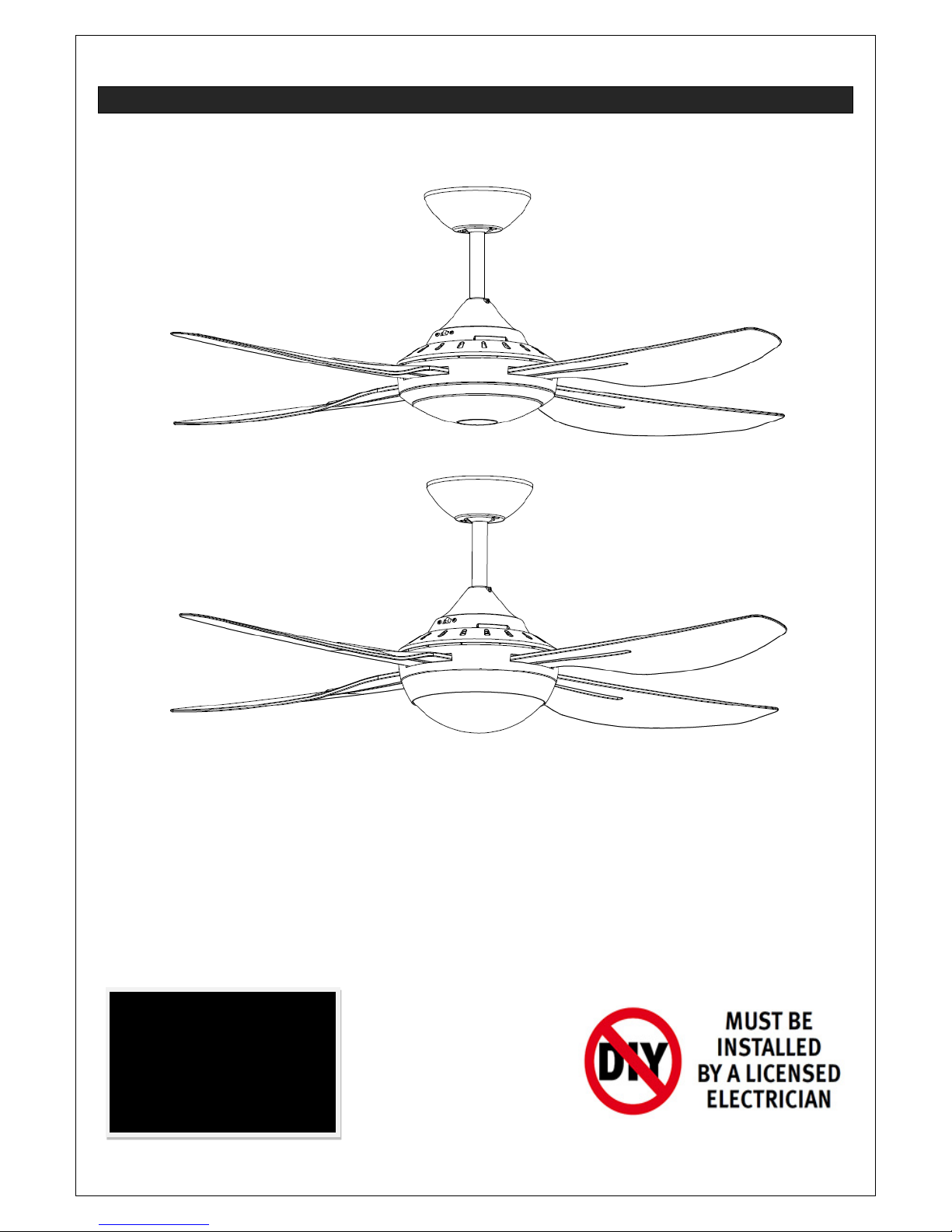
(This photo is for reference only; it does not mean you are purchasing an identical product.
Fan picture is for illustration purposes on ly. S t y les may vary according to the particular model.)
Ceiling Fan Installation Manual, Rev 1.0
HARMONY II SERIES
Models:
HAR1204WH, HAR1204WH-L, HAR1204TI, HAR1204TI-L
INSTALLATION
OPERATION
MAINTENANCE
WARRANTY INFORMATION
CAUTION
Read Instructions Carefully
For Safe Installation and
Fan Operation
2
THANK YOU FOR PURCHASING
Thank you for purchasing this quality Ventair ceiling fan. To ensure correct function and safety, please
read all instructions before using the product and keep all instructions for future reference.
SAFETY PRECAUTIONS
1. The appliance is not intended for use by persons (including children) with reduced physical, sensory
or mental capabilities, or lack of experience and knowledge, unless they have been given
supervision or instruction concerning the use of the appliance by a person responsible for their
safety.
2. Children should be supervised to ensure that they do not play with the appliance.
3. An all-pole disconnection switch must be incorporated into the fixed wiring, in accordance with local
wiring rules.
WARNING:
FOR SAFE USE OF THIS FAN AN ALL-
POLE DISCONNECTION MUST BE
INCORPORATED INTO THE FIXED WIRING IN ACCORDANCE WITH THE WIRING
RULES.
As outlined in clause 7.12.2 of AS/NZS 60335-1 for meeting the minimum electrical safety of
this standard.
Please note warranty will be void if installation is without an all-pole disconnection
incorporated in the fixed wiring in accordance with the wiring rules.
Example: If a fan is connected to a circuit that can be isolated via an all-pole safety switch at
the switchboard, then this is considered to be an all-pole disconnection to the ceiling fan
electrical circuit, meeting the requirements of clause 7.12.2 of AS/NZS 60335.1.
A single-
pole switch also must be placed in the same room as the fan as per local
wiring regulations AS3000
4.
Do not dispose of electrical appliances as unsorted municipal waste, use separate collection
facilities. Contact your local government for information regarding the collection systems available. If
electrical appliances are disposed of in landfills or dumps, hazardous substances can leak into the
ground water and get into the food chain, damaging your health and well-being.
5. The structure to which the fan is to be mounted must be capable of supporting a weight of 30kg.
6. The fan should be mounted so that the blades are at least 2.1m above the floor in Australia.
7. Only a licensed electrician should execute the installation.
3
BEFORE INSTALLATION
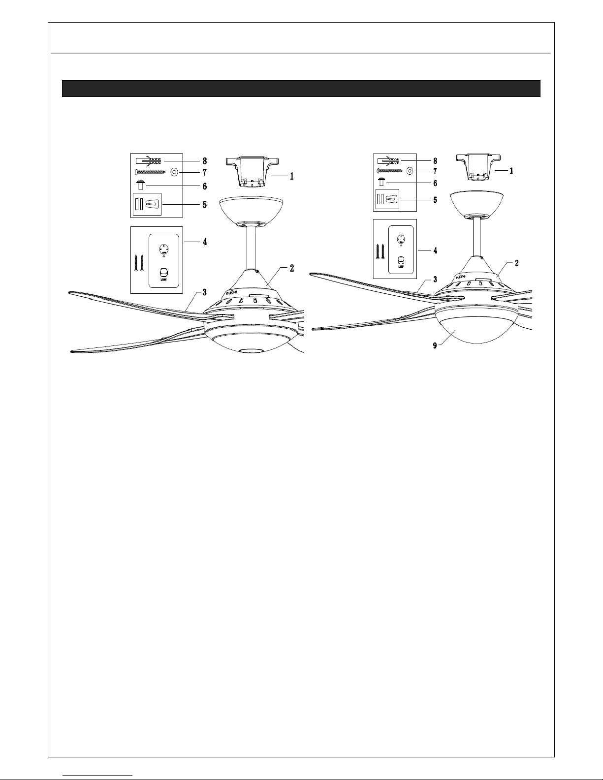
Unpack the fan and carefully identify the parts. Please refer to Fig 1.
`
FAN WITHOUT LIGHT
FAN WITH LED LIGHT
1. Mounting bracket x 1 1. Mounting bracket x 1
2. Pre-assembled fan motor, down rod, canopy
and bottom cover x 1
2. Pre-assembled fan motor, down rod, canopy
and bottom cover x 1
3. Blades x 4 3. Blades x 4
4. Wall switch x 1 4. Wall switch x 1
5. Balancing kit x 1 5. Balancing kit x 1
6. Blade screws x 9 (1 x spare) 6. Blade screws x 9 (1x spare)
7. Wooden screws for mounting bracket x 2 7. Wooden screws for mounting bracket x 2
8. Plastic anchors x 2 8. Plastic anchors x 2
9. Light kit x 1 –
LED driver
LED panel
Plastic diffuser
Fig. 1
4
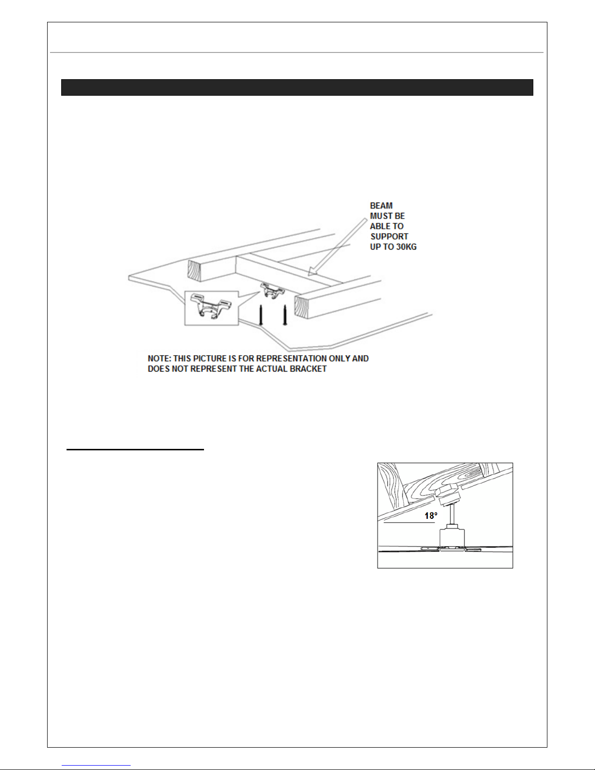
INSTALLING THE MOUNTING BRACKET
• The ceiling fan must be installed in a location so that the blades are a minimum 300mm spacing
from the tip of the blade to the nearest objects or walls.
• Secure the hanging bracket to the ceiling joist or structure that is capable of carrying a load of at
least 30kg, with the two long screws provided. Ensure at least 30mm of the screw is threaded into
the support.
NOTE: The bracket screws provided are for use with wooden structures only. For structures
other than wood, the appropriate screw type MUST be used.
Angled Ceiling Installation
This fan hanging system supports a maximum 18-degree angled
ceiling installation.
Fig. 2
Fig. 3

5
HANGING THE FAN
Lift the fan assembly onto the mounting bracket. Ensure the registration slot (A) of the hanger ball is
positioned on the stopper (B) of the mounting bracket (C) to prevent the fan from rotating when in
operation. (Fig.4)
BLADE INSTALLATION
BLADE A TT ACHMENT (Fig. 5)
1. Remove the top motor housing from the fan body by turning the top motor housing anticlockwise.
2. Insert the blade into the square slot of the motor.
3. Secure the blade on the bracket by using 2 motor screws, ensuring they are tightened
simultaneously.
4. Once completed, repeat the process on the remaining blades.
5. Replace the top motor housing.
Fig. 4
Fig. 5

6
ELECTRICAL WIRING DIAGRAM
WARNING: FOR YOUR SAFETY ALL ELECTRICAL CONNECTIONS MUST BE UNDERTAKEN BY A
LICENSED ELECTRICIAN.
NOTE: AN ADDITIONAL ALL POLE DISCONNECTION MUST BE INCORPORATED IN THE FIXED
WIRING IN ACCORDANCE WITH THE WIRING RULES.
NOTE: Wiring diagram includes the light kit wiring. The light wiring diagram and switch is omitted when
no light kit is used with the ceiling fan.
USE WITH WALL SWITCH WIRING DIAGRAM:
Fig.6

7
USE WITH REMOTE WIRING DIAGRAM: (REMOTE sold separately)
1/ Remote without plugs
2/ Remote with plugs
Fig. 8
Fig. 7

8
FINISHING THE INSTALLATION
After completing the electrical connection at the m ounting bracket terminal block, connect the ceiling
fan wiring by the quick connector plug.
Cover the mounting bracket with the canopy. Ensure all electrical wiring is tucked inside the canopy
and that the wires are not damaged during this step. Secure the canopy to the hanger bracket using
the screws provided.
How to replace the LED driver (For models with light kit)
NOTE: Always turn OFF the power at the mains switch before attempting to replace the LED driver.
Loosen the screw (A) to lift the top housing (B). Replace the LED driver by unpluggi ng the connectors (C,
D). Reposition the top housing and secure it on the down rod by screw.
Fig. 9
Fig. 10

9
REPLACING THE LED PANEL (For models with light kit)
NOTE: Always turn OFF the power at the mains switch before attempting to replace the LED panel.
1. Use a slotted screwdriver to dis-assemble the plastic diffuser carefully.
2. Loosen the 4 screws (B) and keep the screws. Replace the LED panel by unplugging the connectors
(A).
3. Re-tighten the 4 screws, re-assemble the plastic diffuser.
Fig. 12
Fig. 11

10
USING YOUR CEILING FAN
FAN WALL CONTROL
Turn on the power and check the operation of the fan.
• OFF Position – Fan off
• 3rd Position – Low fan speed
• 2nd Position – Medium fan speed
• 1st Position – High fan speed
Light Control
• Toggle Switch – On/off
REVERSE FUNCTION
Your ceiling fan can operate either in fan mode or reverse fan mode.
SUMMER Mode: The reverse switch should be in the “left” (SUMMER) position to rotate the fan in an
anticlockwise direction. The airflow will be directed downwards, for cooling in summer.
WINTER Mode: The reverse switch should be in the “right” (WINTER) position to rotate the fan in a
clockwise direction. The airflow will be directed upwards, for energy conservation in winter.
Fig. 14
Fig. 13

11
AFTER INSTALLATION
WOBBLE:
NOTE: CEILING FANS TEND TO MOVE DURING OPERATION DUE TO THE FACT THAT THEY ARE
MOUNTED ON A RUBBER GROMMET. IF THE FAN WAS MOUNTED RIGIDLY TO THE CEILING IT
WILL CAUSE EXCESSIVE VIBRATION. MOVEMENT OF A FEW CENTIMETRES IS QUITE
ACCEPTABLE AND DOES NOT SUGGEST ANY PROBLEM.
TO REDUCE THE FAN WOBBLE: PLEASE CHECK THAT ALL SCREWS WHICH FIX THE
MOUNTING BRACKET AND DOWN ROD ARE SECURE.
NOTE: This fan has been precision balanced at the factory but may need re-balancing. Balancing kit
supplied can be used if required.
NOISE:
When it is quiet (especially at night) you may hear occasional small noises. Slight power fluctuations and
frequency signals superimposed in the electricity for off-peak hot water control, may cause a change in
fan motor noise. This is normal. Please allow a 24-hour “breaking-in” period, most noises associated
with a new fan disappear during this time. Please note that this is not a product fault and as such is not
covered under warranty – All electric motors are audible to some extent.
CARE AND CLEANING:
• Periodic cleaning of your ceiling fan is the only maintenance required. Use a soft brush or lint free
cloth to avoid scratching the paint finish. Please turn power off when you do so.
• Do not use water when cleaning your ceiling fan. It could damage the motor or blades and create the
possibility of an electrical shock.
• The motor has a permanently lubricated ball bearing so there is no need to oil.
• Periodic tightening of all screws may be required if fan develops a wobble or noise
NOTE: Always turn off the power at the main switch before attempting to clean your fan.
Ceiling Fan model Rated Voltage
Rated Power
(motor)
Rated Power
(lamp)
HAR1204 220 - 240 VAC 75W N/A
HAR1204-L 220 - 240 VAC 75W 18W, LED, 4000K
TECHNICAL INFORMATION

12
IMPORTANT FACTS
All electric motors, including fan motors make some noise and may feel hot if touched – this is NOT A
FAULT. Ceiling fans tend to move during operation as they are not generally rigid-mounted. Rigid
mounted ceiling fans generate excessive vibration (which leads to noise) and stress on their mountings.
Movement in a ceiling fan is not uncommon and does not suggest the fan will fall down. Some fans
wobble more than others, even in the same model.
Fan lights can rattle; if they are not supplied with a fan, they are not covered by warranty.
Fan Operation:
A ceiling fan rotates much more slowly than an electric desk fan; it cools people effectively by introducing
slow movement into the otherwise still, hot air of a room, inducing natural evaporative cooling. Fans
never actually cool air, unlike air-conditioning equipment, but use significantly less power.
Normal Wear and Tear
Threaded components working slightly loose, or blade carriers becoming slightly bent due to vigorous
cleaning or bumping can cause extra wobble and noise. This in not covered under warranty, but a little
care and maintenance can reduce or prevent this problem.
Night Noises
This is the biggest cause of service calls, which are outside the manufacturer’s warranty. If a fan has a
fault, then it would be noticeable at ALL TIMES. Obviously when everything is quiet at night you will be
more inclined to hear small noises, which may not be noticeable at other times. Even slight signals super
imposed in your electricity supply for off peak hot water control may cause a change in the fan motor
noise, which is deemed normal.
WARRANTY INFORMATION
• If you consider there are faults relating to the installation, contact your installer to rectify.
• If you consider there is an manufacturer defect to the fan motor, contact the warranty service line on
1300 665 926, or log the warranty at www.ventair.com.au/warranty
You will need to provide the following information:
• the name and contact details of the licensed electrician installer
• the brand, model number and serial number (located on top of the motor)
• the date and place of purchase of the unit.
• the owners name, address and telephone contact numbers
• the nature of the fault
The cost of a service person will only be paid for manufacturer defect. Once a service person has been
out, if any fault is found to be an installation or user fault, the charges will be applied to the fan owner.
 Loading...