

Vent-a-Hood SL6 User Manual
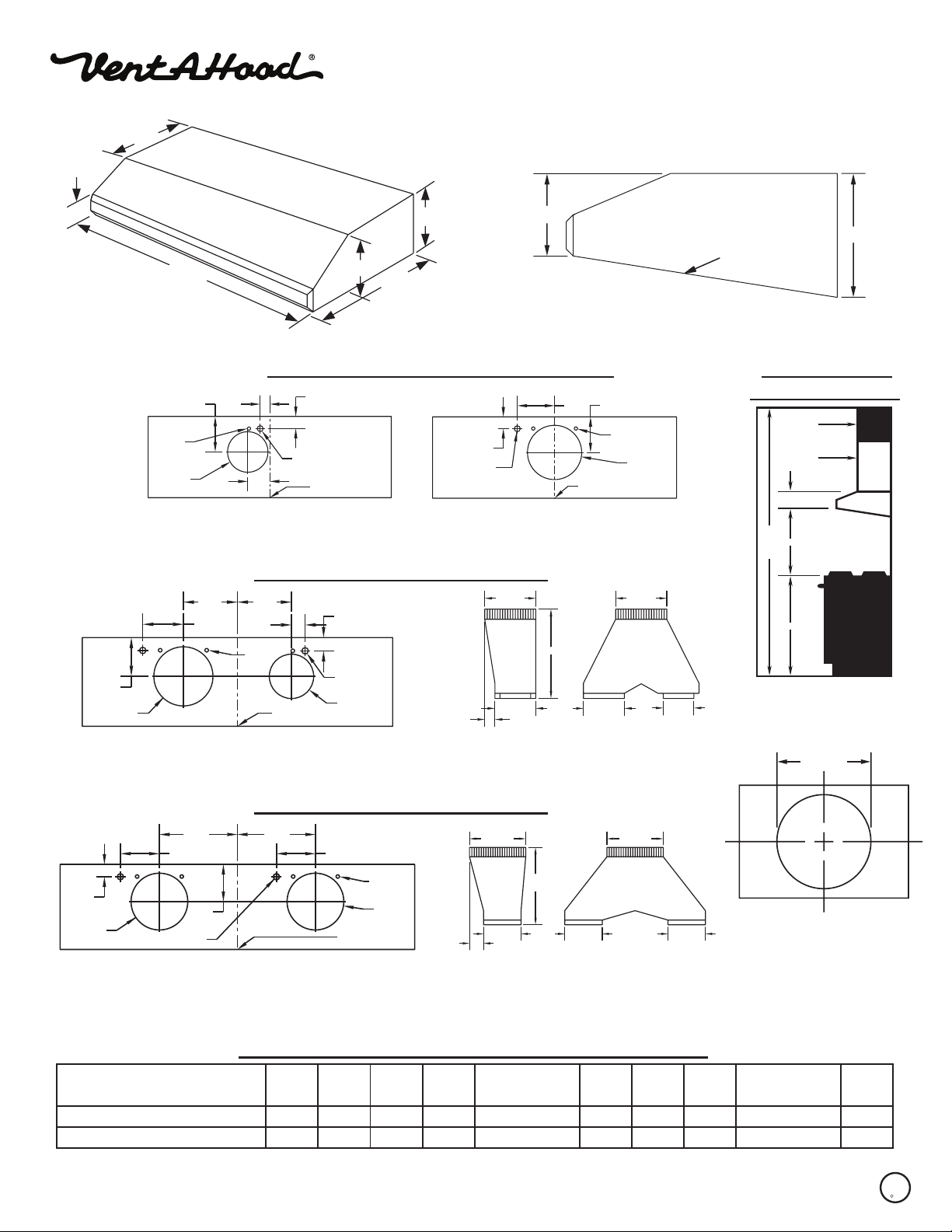
UNDER CABINET RANGE HOOD SPECIFICATIONS
SL6/SLH6 “H” in part number indicates halogen lighting. WL-1 warming lights are available on selected
models.
12”
SL6/SLH6 SIDE VIEW
2”
WIDTH
6”
19 ½”
Connection Diagrams (30”- 48” Widths) Recommended
1 ¾”
Electrical
Centerline
Wall Side
of Hood
Vent
Hole
6” Outlet
1 ⁄”5 ¼”
3 ¼”
300 CFM B100 Single Blower 600 CFM B200 Dual Blower
(Top View) (Top View)
Connection Diagram (42” - Wider)
7 ⁄”
1 ⁄”
Vent
Holes
Centerline
of Hood
1 ¾”
Electrical (2)
6” Outlet
Wall Side
5 ¼”
8” Outlet
7 ⁄”
5 ½”
900 CFM B200 Dual & B100 Single Blower
(Top View)
9”
6”
SL6/SLH6
Wall Side
1 ¾”
Electrical
10” Round 10” Round
17 ½”
8” Round
2”
VP562 Transition (Optional) For B300
(B200 Dual Blower & B100 Single Blower)
5 ¼”5 ½”
Vent
Holes
8” Outlet
Centerline
of Hood
8” Round 6” Round
Sloped
Bottom
Mounting Height*
Soffit
Cabinets
6”
21”-24”
8’ Ceiling
36”
*Exceeding recommended
mounting height may
compromise performance.
10” OR 12”
Round
9”
Connection Diagram (48” - Wider)
11” 11”
1 ¾”
8” Outlet
5 ½”
5 ¼”
Electrical (2)
5 ½”
Centerline
of Hood
Wall Side
Vent
Holes
8” Outlet
1200 CFM Double B200 Dual Blowers
(Top View)
12” Round 12” Round
16 ½”
3”
8” Round
8” Round 8” Round
VP563 Transition (Optional) For B400
(Double B200 Dual Blowers)
VP562/VP563
transition
centers outlet
over top of hood
Electrical/Mechanical Specifications For Blower Units
CFM
SP@0.0”
300
600
Equivalent CFM
450
900
1.7
3.4
*
1550
1550
Model
B100 Single
B200 Dual
*
Note: Add 2.5 amps for each warming light and 0.5 amp for each halogen light. Hood is available with fluorescent light (1 for each single or dual blower) or with halogen lights (2 lights: 30” - 41”, 3 lights: 42” - 53”, 4 lights: 54” - 66”, +1 light for each 16” if over 66”).
#
Because the Magic Lung
than other filtration systems. When comparing the Magic Lung
®
uses centrifugal filtration rather than conventional baffle or mesh filters, the Magic Lung® blower can handle cooking equipment with higher cubic feet per minute (CFM) requirements and can deliver equivalent CFM much more efficiently
Volts Amps RPM
115
115
®
with other blower units made by other manufacturers, use the “Equivalent CFM”.
#
SP@0.1”
CFM
286
572
SPECIFICATIONS SUBJECT TO CHANGE WITHOUT NOTICE Rev. 04/08
CFM
SP@0.2”
270
540
CFM
SP@0.3”
240
480
Minimum Round
Duct Size
6” (or equivalent)
8” (or equivalent)
Square
Inches
28
50
U
CUS
R
L
 Loading...