

Vent-A-Hood RM1000, RM1500 INSTALLATION INSTRUCTIONS
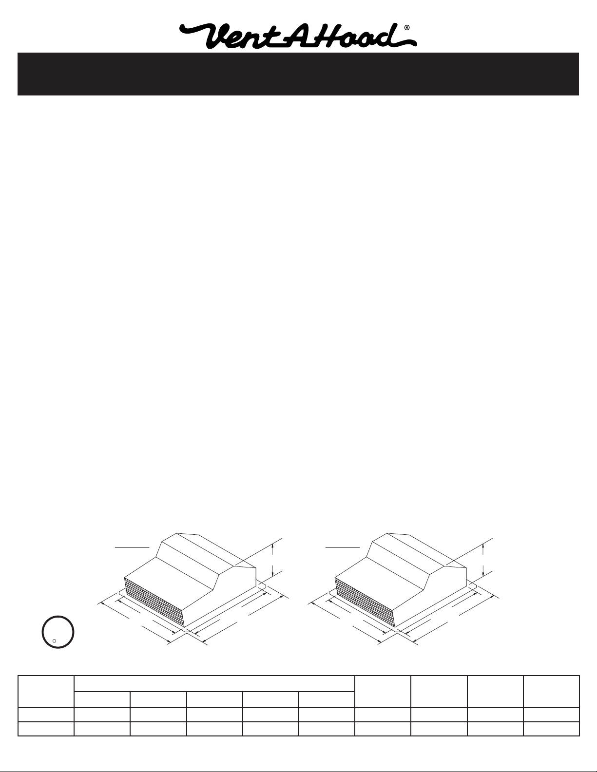
24”
10”
20”
28”
24 ¾”
RM1000
U
L
CUS
R
24”
12 ¼”
20”
28”
24 ¾”
RM1500
INSTALLATION INSTRUCTIONS
FOR REMOTE BLOWER MODEL RM1000 & RM1500
READ AND SAVE THESE INSTRUCTIONS
WARNING - TO REDUCE THE RISK OF FIRE, ELECTRIC SHOCK, OR INJURY TO PERSONS,
OBSERVE THE FOLLOWING:
A. Use this unit only in the manner intended by the manufacturer.
If you have questions, contact the manufacturer at the
address or telephone number listed on the back cover of
the Homeowner’s Manual.
B. Before servicing or cleaning unit, switch power off at the
service panel and lock the service disconnecting means to
prevent power from being switched on accidentally. Then
the service disconnecting means cannot be locked, securely
fasten a prominent warning device, such as a tag, to the
service panel.
C. Installation work and electrical wiring must be done by
qualied person(s) in accordance with all applicable codes
and standards, including re-rated construction codes and
standards.
D. Sufcient air is needed for proper combustion and exhausting
of gases through the ue (chimney) of fuel burning equipment
to prevent back drafting. Follow the heating equipment
manufacturer’s guideline and safety standards such as
those published by the National Fire Protection Association
(NFPA), and the American Society for Heating, Refrigeration,
and Air Conditioning Engineers (ASHRAE), and the local
code authorities.
E. When Cutting or drilling into wall or ceiling, do not damage
electrical wiring or other hidden utilities.
WARNING
1. TO REDUCE THE RISK OF FIRE, USE ONLY METAL
DUCTWORK.
2. THIS FAN IS UL LISTED FOR USE WITH VENT-A-HOOD
MODEL B210R.
CAUTION
1. FOR GENERAL VENTILATION USE ONLY. DO NOT USE
TO EXHAUST HAZARDOUS OR EXPLOSIVE MATERIALS
AND VAPORS.
INSTALLATION TIPS
1. For best performance, keep duct length and number of
elbows to a minimum. 10” round ducting or equivalent is
recommended.
2. Select a location that is free of obstacles such as heating and
air conditioning ducts, water pipes, electrical wiring, etc.
3. Position discharge of the blower down towards ground level
and away from prevailing winds to minimize back drafts.
4. For best appearance, locate the fan on the rear of the house,
below the top of the roof line.
F. Ducted fans must always be vented to the outdoors.
PRODUCT SPECIFICATIONS
Model
RM1000 945 922 884 852 770 120 3.2 60 10"
RM1500 1500 1455 1410 1375 1295 120 5.0 60 10"
L101 0810A Page 1
0.0" Ps 0.1" Ps 0.2" Ps 0.3" Ps 0.5" Ps
CFM Ratings and Electrical Specications
CFM At Static Pressure Ps = Inches of Water
Volts Amps Hz
Duct
Size
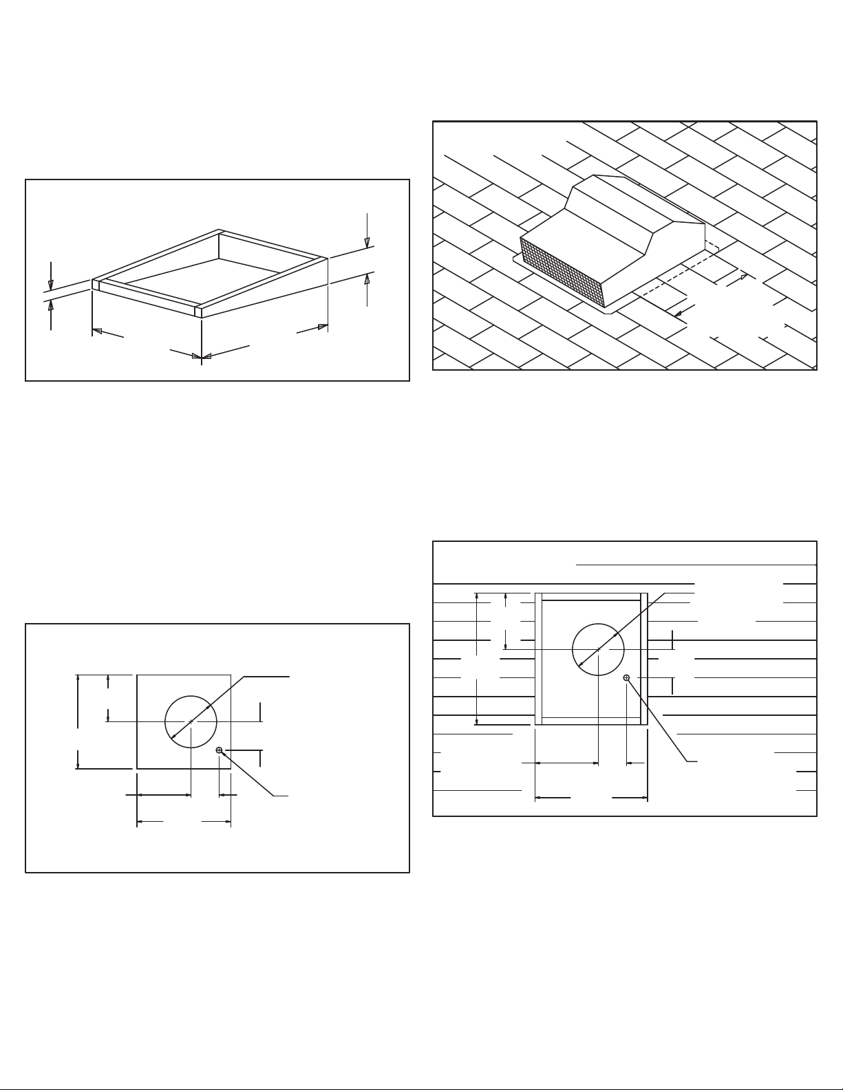
FIGURE 1
5 ½”
28”
24 ¼”
2”
FIGURE 2 - ROOF MOUNT
10”
20”
11 ½”
6”
20”
1 ¼” DIA.
HOLE
6”
11” DIA.
HOLE
FIGURE 3
20”
MINIMUM
FIGURE 4
12”
28”
13 ½”
6”
24”
1 ¼” DIA.
HOLE
6”
11” DIA.
HOLE
PREPARE LOCATION AND INSTALL BLOWER
FLAT OR LOW SLOPE ROOF MOUNT
1. For at roofs having a pitch less than 1-1/2” of rise per 12”
length, mount the blower on a roof curb as shown in Figure
#1.
2. Position the blower so that discharge-end of the blower slopes
downward and away from prevailing winds.
3. Use ashing and roong mastic to prevent leaks between
the roof, the curb, and the blower.
4. Cut holes for ducting and electrical wiring as shown below.
TYPICAL ROOF MOUNT
1. Position the blower so that discharge-end of the blower slopes
downward and away from prevailing winds.
TYPICAL ROOF MOUNT, CONTINUED
6. Fasten the blower to the roof using the mounting screws
provided.
7. Apply roof mastic between the shingles, the remote blower,
and any exposed screw heads.
WALL MOUNT WITH LAP SIDING
1. Remove siding from the 24” x 28” area as shown in Figure
#4. CAUTION: Do not cut through the wooden sheathing
behind the siding.
2. Center the blower duct opening between roof rafters.
3. Remove shingles from the 20” x 20” area and cut openings
for ducting and electrical wiring as shown in Figure #2.
4. Apply a quality grade of roof mastic between the bottom of the
remote blower and the roof. WARNING: Failure to properly
5. For proper drainage, shingles must fully cover the blower’s
L101 0810A Page 2
seal between the remote blower and the roof surface may
result in leaks, resulting in damages to roong and ceiling
material.
rear ashing ange and not less than 20” of the side anges
as shown in Figure #3. The ashing on the discharge-end of
the blower must rest on top of the roof shingles.
2. Use furring strips to frame in around the siding. For best
appearance, the thickness of the strips should be equal to
or greater than the thickness of the siding.
3. Anchor the frame securely to the sheathing with glue and
wood screws. Caulk all joints to prevent water leakage.
4. Cut openings for ducting and electrical connector as shown
above.
5. Apply caulk around the front face of the furring strips.
6. Fasten the blower to the frame using the screws provided.
 Loading...