

Page 1
U
L
CUS
R
Read and Save These Instructions
All Hoods Must Be Installed By A Qualied Installer
INSTALLATION INSTRUCTIONS
WALL MOUNT RANGE HOOD WITH
M600 OR M1200 BLOWER
Read All Instructions Thoroughly Before Beginning Installation
WARNING - TO REDUCE THE RISK OF FIRE, ELECTRIC SHOCK,
OR INJURY TO PERSONS, OBSERVE THE FOLLOWING:
A. Installation work and electrical wiring must be done by qualied person(s)
in accordance with all applicable codes and standards, including rerated construction. Switch power off at service panel and lock the service
disconnecting means to prevent power from being switched on accidentally
during installation.
B. When cutting or drilling into wall or ceiling, do not damage electrical wiring
and other hidden utilities.
C. Ducted fans must always be vented to the outdoors.
D. Sufcient air is needed for proper combustion and exhausting of gases
through the ue (chimney) of fuel burning equipment to prevent back
drafting. Follow the heating equipment manufacturer’s guideline and
safety standards such as those published by the National Fire Protection
Association (NFPA), and the American Society for Heating, Refrigeration
and Air Conditioning Engineers (ASHRAE), and local code authorities.
E. ASHRAE residential ventilation standard 62.2 limits exhaust fans (total) to
a maximum of 15 CFM per 100 square feet of occupiable space, unless a
back drafting test is performed or make-up air is provided. Consult a local
HVAC engineer for make-up air evaluation.
WARNING - TO REDUCE THE RISK OF FIRE, USE ONLY METAL
DUCTWORK
Page 1L157 0311A
Page 2
Ducting Do’s and Don’ts
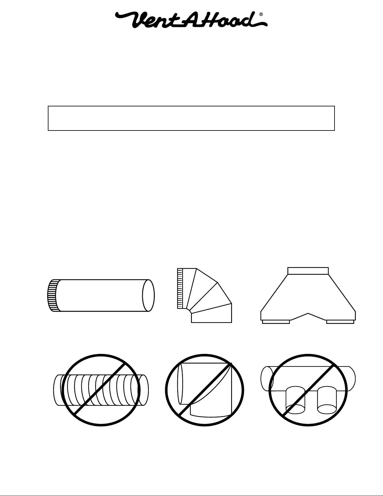
NEVER restrict the duct size. The single blower unit (M600) requires 6” round duct or equivalent
(28 square inches), and the dual blower unit (M1200) requires 10” round duct or equivalent
(79 square inches). Using Vent-A-Hood ducting products (back page) will ensure proper
efciency.
Blower Duct Size Sq. Inch Area Vent-A-Hood Transition
Single (M600) 6” round or equivalent 28” N/A
Dual (M1200) 10” round or equivalent 79” VP566 (Inlcuded)
Do not use exible or corrugated duct. This type of duct will restrict airow and reduce
performance. Only use smooth, galvanized, metal duct. Observe local codes regarding special
duct requirements and placement of duct against combustibles. Make the duct run as short
and as straight as possible with as few turns as possible. Avoid sharp-angled turns. Instead,
use smooth, gradual turns such as adjustable elbows or 45 degree angled turns. For duct runs
over 20 feet, increase the duct diameter by one inch for every ten feet of duct. A 90 degree
elbow is equal to 5 feet of duct. Using Vent-A-Hood roof jacks or wall louvers (back page) will
ensure proper efciency. Airow must not be restricted at the end of the duct run. Do not use
screen wire or spring-loaded doors on wall louvers or roof jacks. Do not terminate venting into
an attic or chimney. Where possible, seal joints with duct tape. The hood must be ducted to the
outdoors without restrictions.
YES
NO
Smooth Duct Smooth Gradual Turn Proper Combining
of Two Ducts
Flexible Duct
Sharp Angled Turns Improper Combining
of Two Ducts
Page 2L157 0311A
Page 3
Electrical
10" Round
Centerline
of Hood
6" Round
Electrical
Centerline
of Hood
Installation Details
1) Read all instructions thoroughly before beginning installation. Note: These instructions apply to standard hoods only.
Custom hoods may require additional specication consideration.
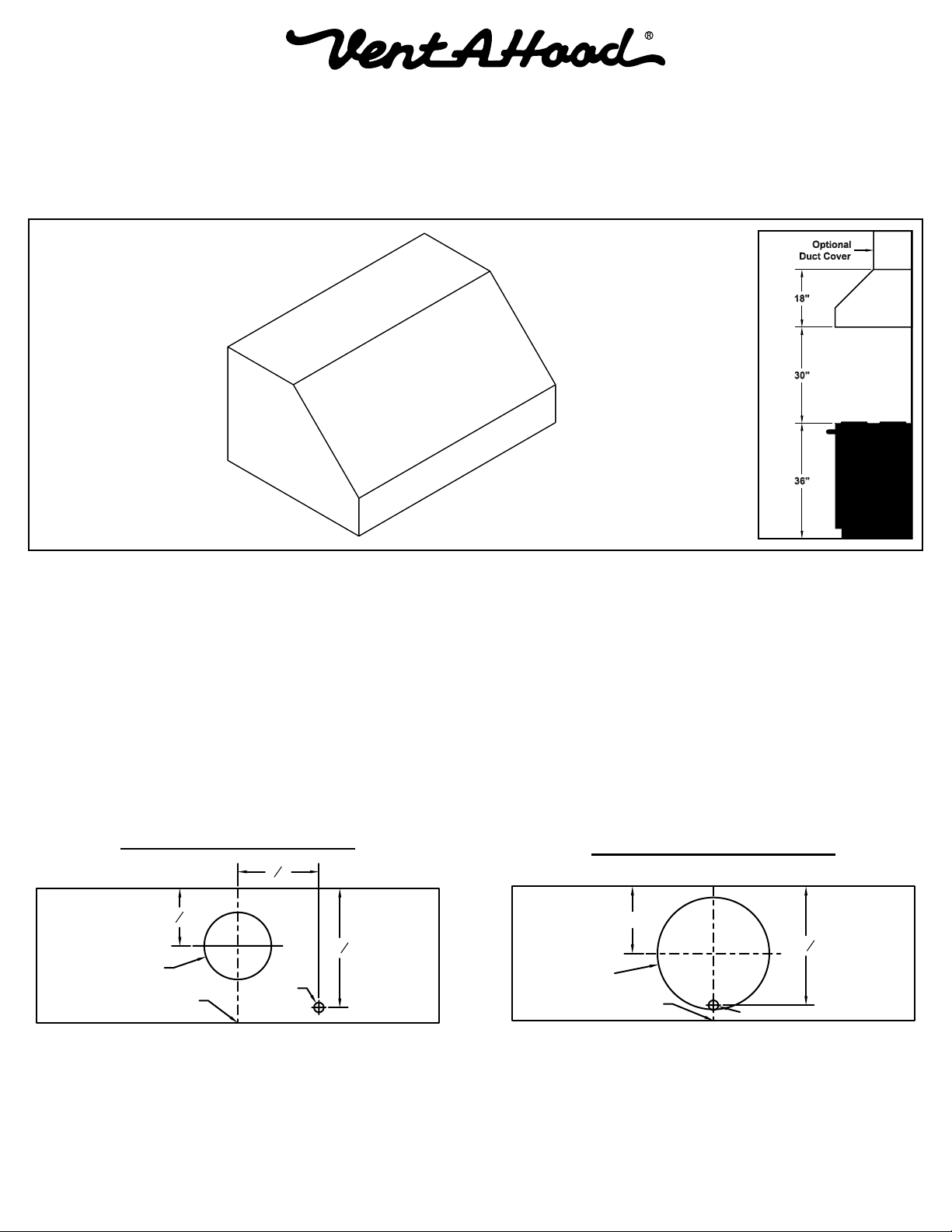
2) When installing a wall mount range hood, it is recommended that the bottom edge of the hood be located no more
than 30” above the cooking surface. Exceeding recommended mounting height may compromise performance.
3) Consult the connection diagrams below for further details on exhaust outlet placement.
Install the duct from the outside of the home down to the exhaust outlet on the hood. The end of the duct should extend
to the top of the hood for the M600 blower or 1" past the top of the transition for the M1200 blower.
Use duct tape to seal all joints. A complete listing of available Vent-A-Hood ducting materials is included on the back
page of this instruction sheet.
Transition heights are as follows:
Single Blower (M600): 6” round duct will connect directly to the top of the hood.
Dual Blower (M1200): Included 10” round transition (VP566) is 9” tall.
M600 Connection Diagram
M1200 Connection Diagram
Single Blower
(Top View)
Dual Blower
(Top View)
Page 3L157 0311A
Page 4
Installation Details Continued
4) Remove the hood from its packaging and place the back of the hood on the oor or countertop in front of the wall
where it will hang.
5) Remove the cardboard lter retaining clip. Sharply push the front of the lter (knob end) into the hood. Raise the back
of the lter from the lter rest and remove the lter through the hood opening. Repeat for each lter.
Warning: Make sure power is off and locked at the service disconnecting
means on the service panel during installation.
6) Hoods are shipped from the factory with the junction box mounted for the M1200 double blower conguration. Remove
the junction box cover. If the M600 single blower will be used, relocate the junction box and ground strap to the offset
location. Install an appropriate 1/2” UL listed electrical wire clamp through the electrical opening on top of the hood.
Install electrical wiring from the service panel to the hood location. Consult the connection diagrams (on previous
page) for further details on electrical placement.
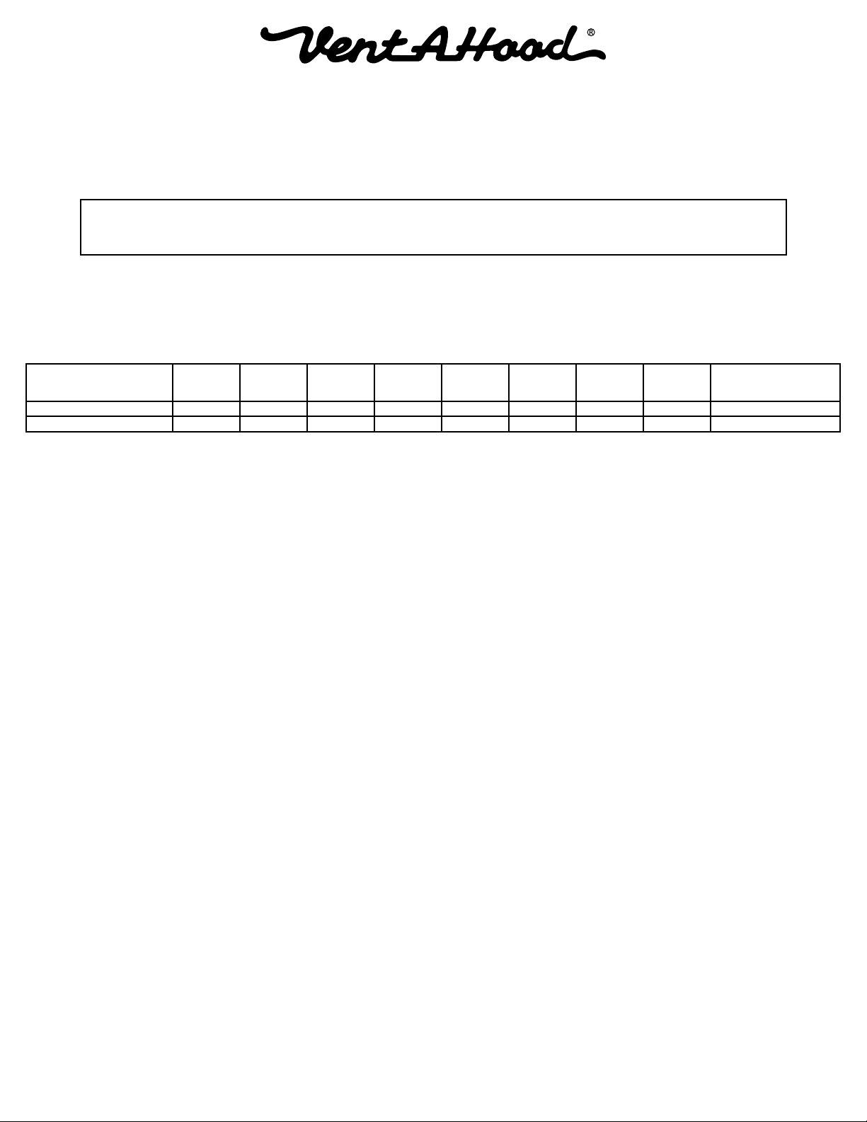
Model Volts Amps* Hz
M600 Single 115 5.0 60 630 625 615 600 580 6" (28 in.2)
M1200 Dual 115 10.0 60 1035 1015 1000 955 915 10" (79 in.2)
* Add 0.5 amp for each halogen light. 2 lights: 30" - 41", 3 lights: 42" - 53", 4 lights: 54"-66"
7) For M600 single blower installation, skip to Step 8. Install the 10" transition (VP566, included) to the top of the hood
with the screws provided. Seal the base of the transition to the hood with duct tape.
8) If using a duct cover, carefully remove the knockouts from the top four corners of the hood. Remove the duct cover
from its packaging and remove the mounting screws from the base of the duct cover. Place the duct cover on the top
of the hood and secure it through the knockout openings using the mounting screws previously removed.
9) Lift the hood (and duct cover assembly) to the location on the wall where it will be installed. Lightly mark the wall with
a short, horizontal mark along the bottom edge of the hood. Remove the hood (and duct cover assembly) from the
wall.
10) On the back side of the hood, measure the distance between the bottom edge of the hood and the top edge of the
wood mounting strip. Measure this distance above the horizontal mark made in Step 9 and lightly mark the wall with
a level, horizontal line. Measure where the center (left to right) of the hood will be and mark the upper, horizontal line
on the wall with a short, vertical centerline.
11) Remove the screws inside the top of the back of the hood that retain the wood strip that is recessed in the mounting
channel. Remove the wood mounting strip from the back of the hood and place the top edge of the strip on the upper,
level, horizontal line on the wall. Referencing the vertical centerline from Step 10, place the mounting strip on the
wall so it is centered (left to right) in the space where the hood will be located. Drill pilot holes in the strip to prevent
splitting. Using proper hardware, attach the mounting strip to the two outermost available wall studs. For hoods wider
than 36", attach to additional wall studs.
CFM
CFM
CFM
CFM
CFM
Minimum Round
Duct Size
12) Hang the hood on the mounting strip by rst aligning the ducting (M1200 blower only) and then aligning the channel
at the top of the back of the hood over the wood mounting strip on the wall. While holding the hood in place, mark
locations on the mounting strip through the two mounting holes in the channel at the top of the hood. Remove the
hood and drill 3/32" pilot holes at the center of the marks in the wood strip to prevent splitting.
13) Insert the electrical wire from the service panel 6" past the electrical wire clamp on the junction box. Tighten the wire
clamp. While securing the slack in the wire, lift the hood up to the wall and hang the hood on the mounting strip, taking
care to properly align the duct connection (M1200 blower). Secure the hood to the mounting strip by installing the
screws (previously removed from the strip in Step 11) into the pilot holes drilled in Step 12.
Page 4L157 0311A
Page 5

Installation Details Continued
14) From inside the hood, using UL listed wire nuts, attach the "neutral" wire to the white lead, the "hot" wire to the black
lead, and the ground wire to the green lead inside the junction box. Replace the junction box cover.
Warning: Do not operate hood without proper ground connection.
15) Raise the blower plate into the hood rst aligning the ducting (M600 blower only) and then aligning the blower mounting
studs to the holes in the blower plate. Secure the blower assembly with the nuts provided. Connect the motor harness
to the socket next to the power cord on the reverse side of the control housing.
16) To install the bafe lter, hold the lter with the knob facing down and toward the front of the hood. Insert the back of
the lter into the back lter channel with enough force to compress the lter spring. Raise the front of the lter inline
with the front lter channel and slowly release the spring force.
To remove the bafe lter, push the lter knob toward the back lter channel to compress the lter spring. Lower the
front of the lter below the front lter channel and slowly release the spring force.
17) Refer to the Owner and Maintenance Guide for proper hood operation. Test all blower and light functions to ensure
they are operating properly.
Page 5L157 0311A
Page 6
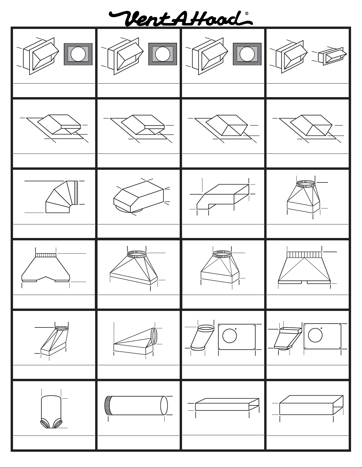
VENTING ACCESSORIES
WALL LOUVER
6”
7”
8”
8 ⁄”
Back
View
1 ½” Flange
WALL LOUVER
11”
11”
Back
View
1 ½” Flange
WALL LOUVER
13”
13”
Back
View
1 ½” Flange
RECTANGULAR WALL LOUVER
3 ¼”
10”
8 ½”
6”
1 ½” FLANGE
2” FLANGE
LOW PROFILE ROOF JACK
(MAXIMUM 4/12 PITCH)
6 ½”
16 ¾”
16 ¾”
LOW PROFILE ROOF JACK
(MAXIMUM 4/12 PITCH)
10 ½”
22 ½”
20 ¾”
ADJUSTABLE ELBOW
6”
7”
8”
VP513 - 8 ½”
VP514 - 9 ⁄”
VP515 - 10 ⁄”
ROUND DUCT PIPE
36”
6”
7”
8”
3 ¼” RECTANGULAR DUCT PIPE
30”
10”
12”
16”
3 ¼”
6” RECTANGULAR DUCT PIPE
24”
8 ½”
6”
OFFSET L & R TRANSITION
FOR ISLAND BLOWERS
8”
12”
5”
16”
SIDE VENT TRANSITION L & R
FOR ISLAND BLOWERS
19”
8”
16”
5”
“Y” TRANSITION
18”
10”
12”
OFFSET KIT - ROUND
16”
11”
6”
7”
10 ½”
OFFSET KIT - RECTANGULAR
16”
11”
6”
11”
3 ¼”
10”
STANDARD ISLAND TRANSITION
8”
9”
16”
5”
CLUSTER BLOWER TRANSITION
18 ½”
12”
11 ¼”
BACK/SIDE VENT ELBOW
12”
6”
16”
8” Round
8 ½”
3 ¼” x 10” BACK VENT ELBOW
4 ¼”
10”
14”
3 ¼”
3 ¼”
MULTI-BLOWER TRANSITION
VP562 - 17 ½”
VP563 - 16 ½”
10”
12”
VP562 - 23 ¼”
VP563 - 30 ½”
3 ¼” x 10” TO 7” TRANSITION
7”
7 ½”
3 ¼”
10”
M1200 STANDARD TRANSITION
10”
9”
8”
21”
LOW PROFILE ROOF JACK
(MINIMUM 4/12 PITCH)
6 ½”
16 ¾”
16 ¾”
LOW PROFILE ROOF JACK
(MINIMUM 4/12 PITCH)
10 ½”
22 ½”
20 ¾”
MODEL DESCRIPTION PRICE
VP526 6” Round
VP527 7” Round
VP528 8” Round
MODEL DESCRIPTION PRICE
VP554 10” Round
MODEL DESCRIPTION PRICE
VP555 12” Round
MODEL DESCRIPTION PRICE
VP538 6” x 8-1/2”
VP560 3-1/4” x 10”
MODEL DESCRIPTION PRICE
VP539 6” Round
VP540 7” Round
VP541 8” Round
MODEL DESCRIPTION PRICE
VP552 10” Round
VP553 12” Round
MODEL DESCRIPTION PRICE
VP539-HP 6” Round
VP540-HP 7” Round
VP541-HP 8” Round
MODEL DESCRIPTION PRICE
VP552-HP 10” Round
VP553-HP 12” Round
MODEL DESCRIPTION PRICE
VP513 6” Round
VP514 7” Round
VP515 8” Round
MODEL DESCRIPTION PRICE
VP561 8” to 6” x 8-1/2”
MODEL DESCRIPTION PRICE
VP559 3-1/4” x 10”
MODEL DESCRIPTION PRICE
VP521 3-1/4” x 10 to 7”
MODEL DESCRIPTION PRICE
VP562 6” & 8” to 10”
VP563 8” & 8” to 12”
MODEL DESCRIPTION PRICE
VP566 M1200 Transition
MODEL DESCRIPTION PRICE
VP565 5” x 16” to 8” Rnd
MODEL DESCRIPTION PRICE
VP564 8” & 8” to 12”
MODEL DESCRIPTION PRICE
VP542 Top Left
VP543 Top Right
MODEL DESCRIPTION PRICE
VP544 Side Left
VP545 Side Right
MODEL DESCRIPTION PRICE
VP529 6” Rnd to 7” Rnd
MODEL DESCRIPTION PRICE
VP550 6” to 3-1/4” x 10”
MODEL DESCRIPTION PRICE
VP517 8” & 8” to 12”
VP518 6” & 8” to 12”
VP551 6” & 8” to 10”
MODEL DESCRIPTION PRICE
VP500 6” Round
VP501 7” Round
VP502 8” Round
MODEL DESCRIPTION PRICE
VP504 3-1/4” x 10”
VP505 3-1/4” x 12”
VP506 3-1/4” x 16”
MODEL DESCRIPTION PRICE
VP507 6” x 8-1/2”
Page 6L157 0311A
 Loading...