

Vent-a-Hood ISLAND RANGE HOOD Installation Instructions Manual

Read and Save These Instructions
All Hoods Must Be Installed By A Qualified Installer
INSTALLATION INSTRUCTIONS
ISLAND RANGE HOOD
Read All Instructions Thoroughly Before Beginning Installation
WARNING - TO REDUCE THE RISK OF FIRE, ELECTRIC SHOCK,
OR INJURY TO PERSONS, OBSERVE THE FOLLOWING:
A. Installation work and electrical wiring must be done by qualified
person(s) in accordance with all applicable codes and standards,
including fire-rated construction. Switch power off at service panel
and lock the service disconnecting means to prevent power from
being switched on accidentally during installation.
B. When cutting or drilling into wall or ceiling, do not damage
electrical wiring and other hidden utilities.
C. Ducted fans must always be vented to the outdoors.
D. Sufficient air is needed for proper combustion and exhausting of
gases through the flue (chimney) of fuel burning equipment to
prevent back drafting. Follow the heating equipment
manufacturer’s guideline and safety standards such as those
published by the National Fire Protection Association (NFPA), and
the American Society for Heating, Refrigeration and Air
Conditioning Engineers (ASHRAE), and local code authorities.
WARNING - TO REDUCE THE RISK OF FIRE, USE ONLY METAL
DUCTWORK
Page 1
L111
(Rev. 02/08)
U
CUS
R
L
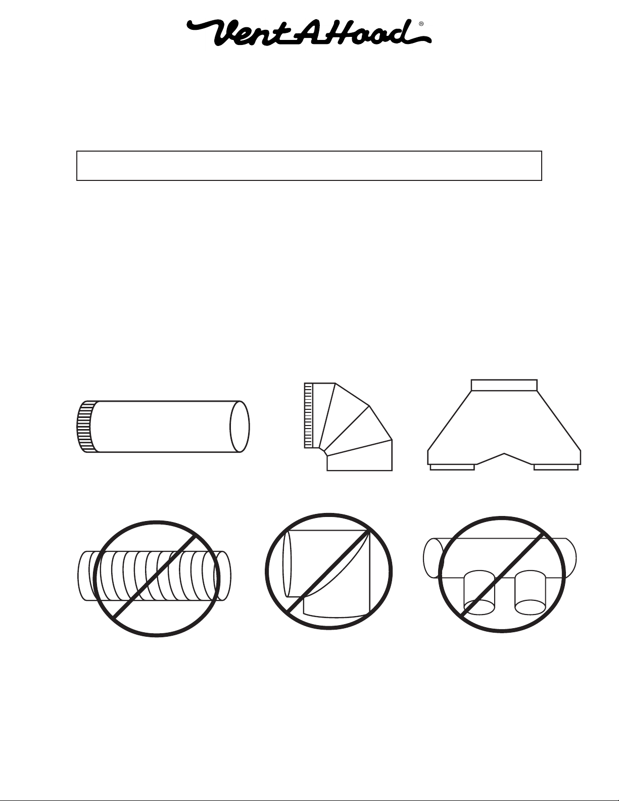
Ducting Do’s and Don’ts
NEVER restrict the duct size. An island dual blower unit (T200) requires 8” round duct or
equivalent (50 square inches). When combining ducts together, the square inch area must
reflect the total square inch area of the ducts being combined. Using the included Vent-A-Hood
transition(s) will ensure proper efficiency.
Blower Duct Size Sq. Inch Area Vent-A-Hood Transition
Island Dual (T200) 8” round or equivalent 50” VP565 (Included)
Do not use flexible or corrugated duct. This type of duct will restrict airflow and reduce
performance. Only use smooth, galvanized, metal duct. Observe local codes regarding special
duct requirements and placement of duct against combustibles. Make the duct run as short and
as straight as possible with as few turns as possible. Avoid sharp-angled turns. Instead, use
smooth, gradual turns such as adjustable elbows or 45 degree angled turns. For duct runs over
20 feet, increase the duct diameter by one inch for every ten feet of duct. A 90 degree elbow is
equal to 5 feet of duct. Using Vent-A-Hood roof jacks or wall louvers (back page) will ensure
proper efficiency. Airflow must not be restricted at the end of the duct run. Do not use screen
wire or spring-loaded doors on wall louvers or roof jacks. Do not terminate venting into an attic
or chimney. Where possible, seal joints with duct tape. The hood must be ducted to the outdoors
without restrictions.
YES
NO
Smooth Duct
Flexible Duct
Smooth Gradual Turn
Sharp Angled Turns
Proper Combining
of Two Ducts
Improper Combining
of Two Ducts
L111
Page 2
(Rev. 02/08)
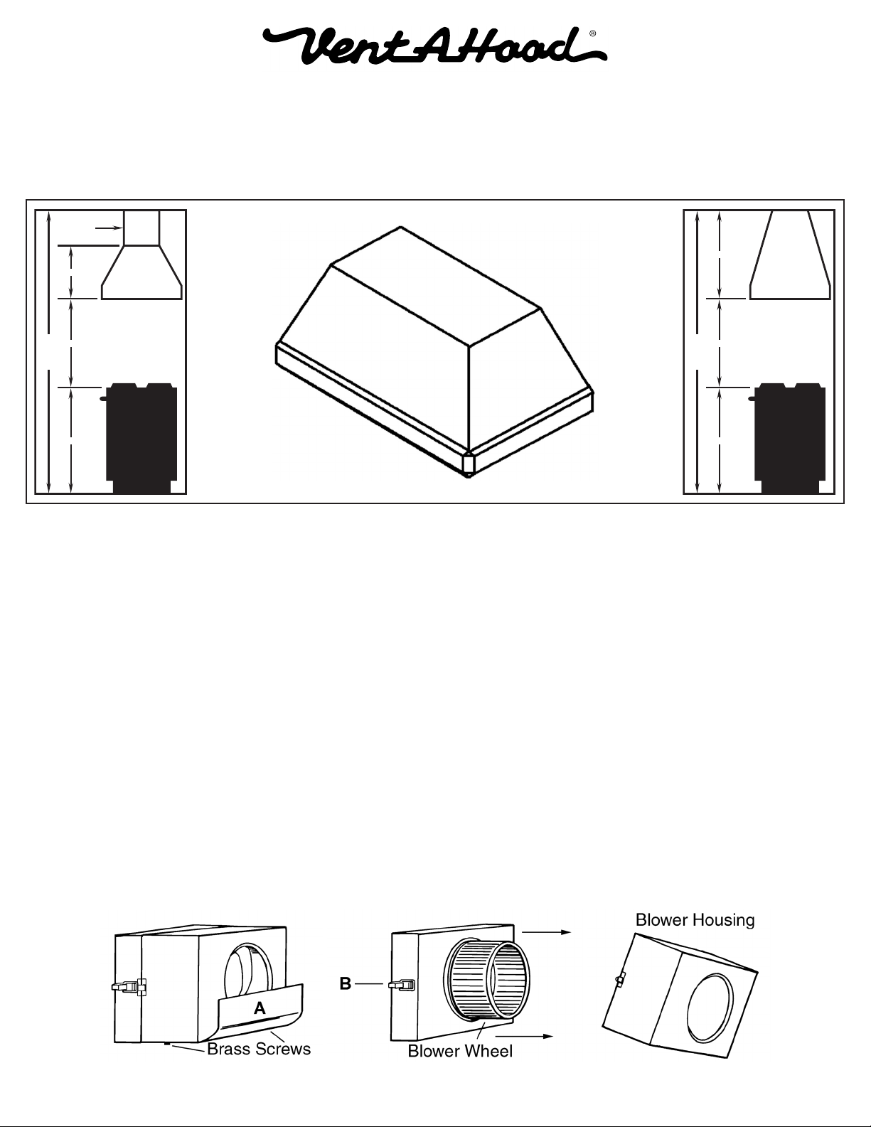
Installation Details
1) Read all instructions thoroughly before beginning installation. Note: These instructions apply to standard hoods only.
Custom hoods may require additional specification consideration.
2) When installing an island range hood, it is recommended that the bottom edge of the hood be located no more than 30”
above the cooking surface. Exceeding recommended mounting height may compromise performance.
Optional
Duct Cover
30”
18”
30”
8’ Ceiling
36”
30”
8’ Ceiling
36”
3) Load-bearing framework in the ceiling is necessary for installation. Additional framework construction may be required.
Do not attach an island hood to a structure that cannot support twice the weight of the hood.
If applicable, remove the duct cover from its packaging and remove the hood-mounting screws from the base of the
duct cover. Install the duct cover to the load-bearing framework in the ceiling using appropriate hardware through the
four inside corner mounting flanges on the top of the duct cover.
4) Install the duct(s) from the outside of the home down to the location of the exhaust outlet(s) on the top of the transition
plus 1”. This will allow the transition to engage 1” inside of the duct. Consult the connection diagrams (on next page)
for further details on exhaust outlet placement.
Use duct tape to seal all joints. A complete listing of available Vent-A-Hood ducting materials is listed on the back page
of this instruction sheet.
Transition height is as follows:
Island Dual Blower (T200): 8” round duct connects to 9” tall VP565 transition (included).
5) Prepare a protective surface on the floor or countertop for the hood. Remove the hood from its packaging and place it
upside-down on the protective surface for access to the inside of the hood.
6) Remove the blower shields (A) by loosening the two brass screws on the bottom of the shield. Gently close the back
draft dampers from the top side of the hood. To remove the blower housings, unsnap the suitcase latches (B) (one on
each side of the housing). The housings should be pulled forward and gently “tipped” to clear the blower wheels and
then out of the hood.
Page 3
L111
(Rev. 02/08)
 Loading...