

Vent-a-Hood 300 CFM B100, 900 CFM B200, 900 CFM B100, 600 CFM B200 Dual, B200 Dual Installation Instructions Manual
Read and Save These Instructions
All Hoods Must Be Installed By A Qualified Installer
INSTALLATION INSTRUCTIONS
WALL MOUNT RANGE HOOD
Read All Instructions Thoroughly Before Beginning Installation
WARNING - TO REDUCE THE RISK OF FIRE, ELECTRIC SHOCK,
OR INJURY TO PERSONS, OBSERVE THE FOLLOWING:
A. Installation work and electrical wiring must be done by qualified
person(s) in accordance with all applicable codes and standards,
including fire-rated construction. Switch power off at service panel
and lock the service disconnecting means to prevent power from
being switched on accidentally during installation.
B. When cutting or drilling into wall or ceiling, do not damage
electrical wiring and other hidden utilities.
C. Ducted fans must always be vented to the outdoors.
D. Sufficient air is needed for proper combustion and exhausting of
gases through the flue (chimney) of fuel burning equipment to
prevent back drafting. Follow the heating equipment
manufacturer’s guideline and safety standards such as those
published by the National Fire Protection Association (NFPA), and
the American Society for Heating, Refrigeration and Air
Conditioning Engineers (ASHRAE), and local code authorities.
WARNING - TO REDUCE THE RISK OF FIRE, USE ONLY METAL
DUCTWORK
Page 1
L110
(Rev. 02/08)
U
CUS
R
L
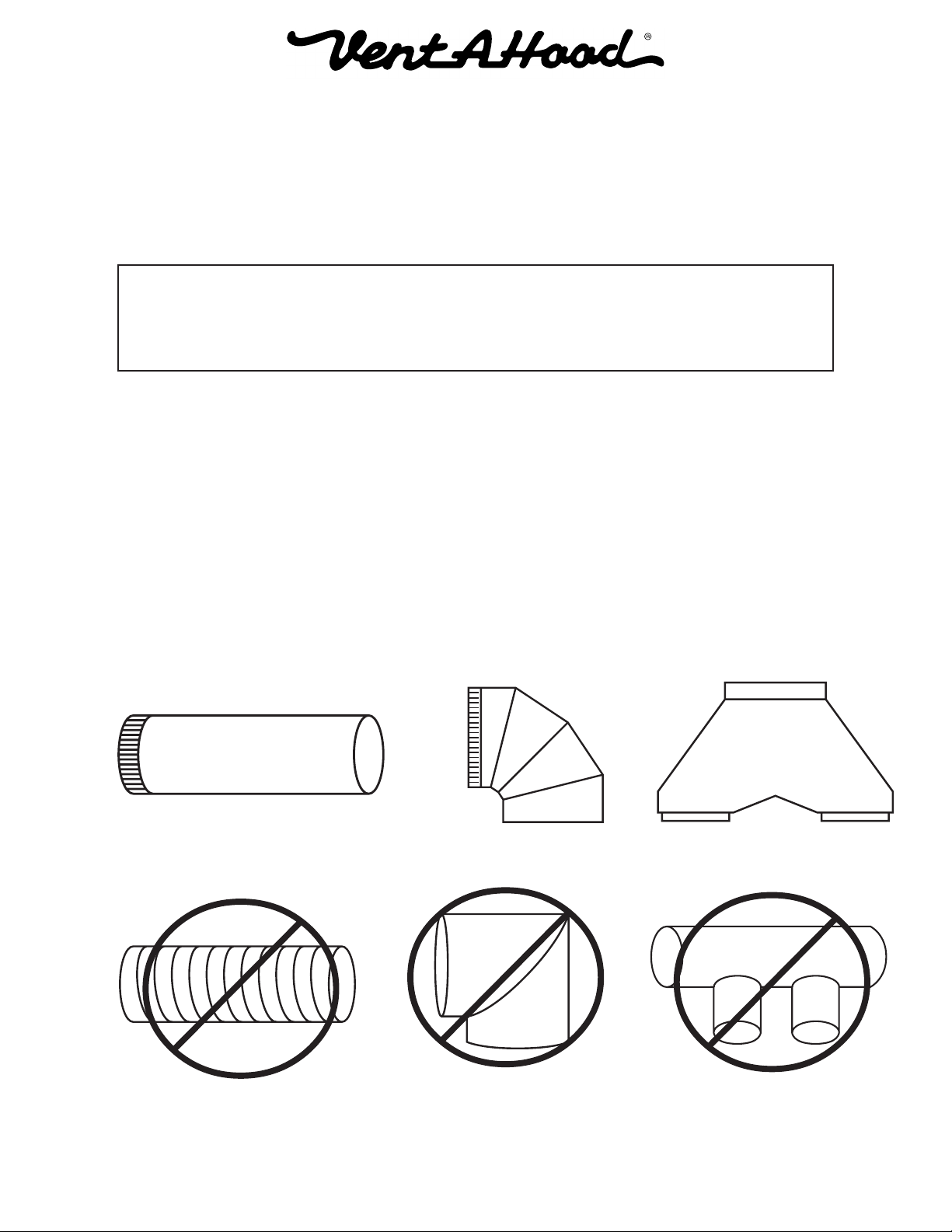
Ducting Do’s and Don’ts
NEVER restrict the duct size. The single blower unit (B100) requires 6” round duct or equivalent
(28 square inches), and the dual blower unit (B200) requires 8” round duct or equivalent (50
square inches). When combining ducts together, the square inch area must reflect the total
square inch area of the ducts being combined. Using Vent-A-Hood transitions (back page) will
ensure proper efficiency.
Blower Duct Size Sq. Inch Area Vent-A-Hood Transition
Single (B100) 6” round or equivalent 28” N/A
Dual (B200) 8” round or equivalent 50” N/A
Single and Dual (B100 & B200) 10” round or equivalent 79” VP562 (Optional)
Two Dual (Two B200s) 12” round or equivalent 113” VP563 (Optional)
Do not use flexible or corrugated duct. This type of duct will restrict airflow and reduce
performance. Only use smooth, galvanized, metal duct. Observe local codes regarding special
duct requirements and placement of duct against combustibles. Make the duct run as short and
as straight as possible with as few turns as possible. Avoid sharp-angled turns. Instead, use
smooth, gradual turns such as adjustable elbows or 45 degree angled turns. For duct runs over
20 feet, increase the duct diameter by one inch for every ten feet of duct. A 90 degree elbow is
equal to 5 feet of duct. Using Vent-A-Hood roof jacks or wall louvers (back page) will ensure
proper efficiency. Airflow must not be restricted at the end of the duct run. Do not use screen
wire or spring-loaded doors on wall louvers or roof jacks. Do not terminate venting into an attic
or chimney. Where possible, seal joints with duct tape. The hood must be ducted to the outdoors
without restrictions.
L110
YES
NO
Smooth Duct
Flexible Duct
Smooth Gradual Turn
Sharp Angled Turns
Page 2
(Rev. 02/08)
Proper Combining
of Two Ducts
Improper Combining
of Two Ducts
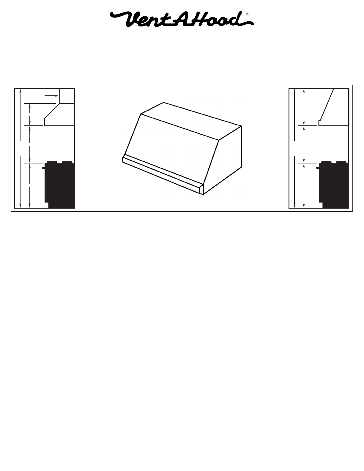
Installation Details
1) Read all instructions thoroughly before beginning installation. Note: These instructions apply to standard hoods only.
Custom hoods may require additional specification consideration.
2) When installing a wall mount range hood, it is recommended that the bottom edge of the hood be located no more than
30" above the cooking surface. Exceeding recommended mounting height may compromise performance.
Optional
Duct Cover
30”
18”
30”
8’ Ceiling
36”
30”
8’ Ceiling
36”
3) Select the appropriate installation method.
Method 1 is suitable for applications where the top of the hood (blower outlet(s) location) is accessible after the hood
is mounted on the wall.
Method 2 is suitable for applications where the top of the hood (blower outlet(s) location) is not accessible after the
hood is mounted on the wall.
4) IF THE HOOD IS TO BE “BACK VENTED”, PROCEED DIRECTLY TO STEP 5.
Consult the connection diagrams (on next page) for further details on exhaust outlet placement.
Method 1: Install the duct(s) from the outside of the home down to the location of the exhaust outlet(s) on the top of
the hood allowing room for the transition (if applicable). If a transition is used, install duct down to the
location of the transition outlet plus 1". This will allow the transition to engage 1" inside of duct.
Method 2: Install the duct(s) from the outside of the home to the ceiling over the exhaust outlet(s) on the hood. The
end of the duct(s) should extend 1" below the ceiling.
Use duct tape to seal all joints. A complete listing of available Vent-A-Hood ducting materials is provided on the back
page of this instruction sheet.
Transition heights are as follows:
Single Blower (B100): 6" round duct will connect directly to the top of the hood.
Dual Blower (B200): 8" round duct will connect directly to the top of the hood.
Single and Dual Blower (B100 & B200): 6" round duct will connect directly to the top of the hood; 8” round will
connect directly to the top of the hood. Optional 10" round combination
transition (VP562, sold separately) is 17 1/2" tall.
Two Dual Blowers (Two B200s): Two 8” round ducts connect directly to the top of the hood. Optional 12”
round combination transition (VP563, sold separately) is 16 1/2” tall.
Page 3
L110
(Rev. 02/08)
 Loading...