

Vent 125 Derapage 2019, 125 Baja RR 2019, 125 Baja 2019, 125 Derapage RR 2019 Use And Maintenance Manual

USE AND MAINTENANCE
MANUAL
VENT 125 Baja + Baja RR / VENT 125 Derapage + Derapage RR

This manual is an integral part of the vehicle and must always be so, even when the
vehicle is sold.
VENT is entitled to modify its own models,
except for the essential characteristics described and illustrated herein.
All rights of electronic memory, reproduction and total or partial adaptation, whatever the means, are reserved in all countries.
Mentions of products or services provided
by third parties are for information purposes
only and do not represent any commitment
whatsoever.
VENT cannot be held liable for the services
or the use of these products.
Edition: 03/2019.
Produced by:
DUESSE SERVICE srl
Samarate (VA)
www.duesse.it
On behalf of:
VENT srl
I - 23815 Introbio (Lecco) Via V. Veneto, 9
Phone: +39 (0341) 901-533 (R.A.)
Fax: +39 (0341) 901-457
E-mail: info@ventmoto.it
2 use and maintenance manual
VENT 125 Baja + Baja RR / VENT 125 Derapage + Derapage RR

MAIN INDEX
SAFETY MESSAGES ....................................... 4
WARNINGS - CAUTION -
GENERAL WARNINGS ................................ 4
CatalytiC exhaust system .................... 4
SAFETY RULES ............................................... 4
Permitted use ........................................... 5
Clothing .................................................... 5
aCCessories ............................................. 5
luggage ..................................................... 5
Fuel ............................................................. 5
engine oil................................................... 6
Brake Fluid ................................................ 6
Cooling Fluid ........................................... 7
exhaust Fumes ......................................... 7
Battery ....................................................... 7
saFe driVing .............................................. 7
Parking ....................................................... 8
VehiCle identiFiCation............................. 9
engine identiFiCation .............................. 9
MAIN ELEMENTS.......................................... 10
main elements on the leFt side ........ 10
main elements on the right side ...... 10
COMMANDS ................................................. 14
start switCh ........................................... 14
start Button .......................................... 14
leFt switCh ............................................. 15
ClutCh Command .................................. 16
aCCelerator Command ....................... 16
Front Brake Command ........................ 16
ComBined Braking Command ............. 16
ClutCh Command leVer ....................... 17
steering loCk ........................................ 17
Fuel taP .................................................... 17
INSTRUCTIONS TO USE THE VEHICLE ..... 20
general CheCks Prior to use ........... 20
ClimBing on and oFF the VehiCle ...... 20
Break-in.................................................... 21
adjusting rear-View mirrors ................ 21
PlaCing the VehiCle on
the side kiCkstand ................................ 22
Fuelling ................................................... 22
STARTING THE ENGINE ............................... 23
on your way ........................................... 24
stoPPing the VehiCle ........................... 25
stoPPing the engine ............................. 25
Preliminary oPerations ...................... 25
SCHEDULED MAINTENANCE SHEETS ...... 27
Parts remoVal ....................................... 29
remoVing the seat ................................ 29
remoVing the leFt Front
ConVeyor ................................................ 29
remoVing the wheels .......................... 30
disassemBling the Front
light BraCket ............................................32
COMMANDS ................................................. 33
engine oil leVel CheCk ........................ 33
Brake Fluid leVel CheCk ..................... 34
Brake lining CheCk ............................... 35
Cooling Fluid leVel CheCk ................. 35
CheCking the tyres .............................. 36
insPeCtions and regulations ............ 37
side kiCkstand ........................................ 37
handleBar ............................................... 37
swingarm................................................. 38
Fuel tank CaP ......................................... 38
air Filter .................................................. 39
transmission Chain .............................. 40
Front susPension ................................. 42
rear susPension ................................... 42
sPark Plug .............................................. 43
Front Brake Command leVer ............ 44
ComBined Braking Command leVer .. 44
ClutCh Command leVer ....................... 45
aCCelerator Command regulation ...... 46
idling sPeed regulation ...................... 46
Battery ..................................................... 47
tyPe oF reCharge ................................. 48
FUSES ............................................................ 48
light Beam ............................................... 49
Front headlight BulBs ....................... 50
rear headlight BulB ............................ 51
Front and rear Blinkers .................... 51
TRANSPORTATION ....................................... 51
CLEANING ..................................................... 52
washing ................................................... 52
storage ................................................... 53
TECHNICAL INFORMATION ........................ 54
VENT 125 Baja + Baja RR / VENT 125 Derapage + Derapage RR
3use and maintenance manual
SAFETY MESSAGES
This symbol indicates a safety message.
When this symbol appears in the
manual, pay particular attention to the
potential risk of harm. Failing to heed the
warnings that contain this symbol may
compromise your own safety as well as
that of other people and of the vehicle!
The following words are used throughout
the manual to indicate:
DANGER
Potential risk of serious injury or death
for the operator or other people.
WARNING
Potential risk of light injuries for the operator or other people, or damage to the
vehicle.
NOTE: The term “NOTE” precedes important information or instructions.
WARNINGS - PRECAUTIONS GENERAL WARNINGS
Before using or operating the vehicle, read
this manual very carefully, paying particular
attention to the chapter “SAFETY RULES”.
Your safety and that of others depend on:
- Being familiar with the vehicle in your
possession;
- Theefciencyandmaintenancestatusof
your vehicle;
- Being familiar with and respecting the
Highway Code;
- Your familiarity with movements on the
vehicle.
To familiarise yourself with the vehicle,
choose an area awayfromtrafcanddevoid of dangers to practice.
VENT thanks you for choosing one of
our products and wishes you a pleasant
drive.
Catalytic discharge system
The catalytic discharge system must be
able to work at high temperatures, which remain for a certain period of time even after
the engine has been turned off.
DANGER
Do not touch or move objects, especial-
ly ammable ones, near the catalytic
discharge system until it is completely
cold.
Park the vehicle away from dry brush or
places accessible to children.
WARNING
To avoid damage to the catalytic discharge system, use only lead-free gasoline.
SAFETY RULES
- To drive this vehicle it is necessary to
possessallrequisitesdenedbythelaw
in force in the country where it is used.
- Taking certain medications, alcohol or
other drugs increases the risk of accidents. Make sure you are psychologically and physically able to drive, focusing particularly on physical fatigue and
drowsiness.
- Anothersignicantcauseofaccidentsis
driver’s inexperience. DO NOT entrust
the vehicle to beginners, and make sure
the driver possesses the necessary requisites to drive.
- Always respect road signs and highway
laws, nationally and locally.
- Avoid sudden manoeuvres, which are
dangerous for yourself and for others (for
4 use and maintenance manual
VENT 125 Baja + Baja RR / VENT 125 Derapage + Derapage RR
example, wheeling, failing to respect the
speed limit etc).
Assess driving conditions:
- Visibility;
- Road conditions;
- Trafc;
- Presence or possible presence of pedestrians.
Rule out and avoid obstacles that may
cause damage to the vehicle or lead to
loss of control of the vehicle.
- Respect and maintain all safety distances.
- Always drive holding the steering wheel
with both hands, with your feet resting on
the driver’s footrests, i.e. In the proper
driving position.
- Pay maximum attention to the act of driv-
ingandtothetrafcontheroad.
- If the vehicle has been in an accident or
has been in a crash or fall, make sure the
command levers, the tubes, the cables,
the braking system, the wheels, the tyres
and all other parts are intact.
If the damage is persistent or if you are
uncertain of its conditions, take the car to
a VENT dealer, where the vehicle will be
tested and inspected.
Always report any case of malfunctioning
to make it easier for the technicians and/
or mechanics to solve the problem.
VENT 125 Baja + Baja RR / VENT 125 Derapage + Derapage RR
Do not drive or allow anyone to drive the
vehicle if the damage it has suffered is
compromising its safety.
- Itis forbiddento carryout anymodica NOTE: Making modications to the vehi-
- It is advisable to follow all national and
- It is forbidden to use the vehicle to race,
Permitted use
Baja models are intended for use on the
road and off-road.
Derapage models are intended exclusively
for use on the road.
Clothing
- Always wear and properly snap shut the
- It is advisable to wear protective gar-
Do not wear exceedingly loose or abun-
DANGER
tion to the vehicle.
cle will result in warranty annulment.
local laws and regulations regarding vehicle equipment.
except for competitions in tracks set
apart for this purpose.
helmet, which must be approved according to the laws in force in the country
where it is being used.
ments in the event of falls, such as jacket, trousers, gloves, boots etc, suitable
for motorcycle use.
dant garments or accessories, as they
may impair driving manoeuvres.
- Do not keep in your pockets any sharp
objects that could potentially cause harm
in a fall, such as:
- Keys;
- Pens;
- Glass containers etc.
This also applies to the passenger.
Accessories:
It is advisable to purchase and install original accessories from a VENT dealer.
Users are personally responsible for choosing and installing accessories.
Luggage
- Be prudent when loading luggage. Do
not overload.
- Maintain the luggage as close as possible to the barycentre of the vehicle.
- Distribute the load uniformly on both
sides to reduce imbalances.
- Theloadmustbermlyanchoredtothe
vehicle.
- Never rest any loads on the handlebars,
swingarm or front mudguard.
- Exceedingly voluminous loads, or anything that protrudes too much from the
limits of the vehicle, may cause crashes and therefore injury and damage to
animals or things and compromise the
stability of the vehicle, with dangerous
5use and maintenance manual

consequences.
-
It is forbidden to transport any load that
protrudes exceedingly or that covers
the acoustic and visual signalling devices.
-
Overloading the vehicle compromises
its stability and manoeuvrability.
Fuel
DANGER
Fuel is highly ammable, harmful for the
health and dangerous for the environment.
DANGER
Do never use your mouth to pump fuel
from the tank using tubes or any other
means.
- Whenllingup thetank,never usefree
ames,do notsmoke,andkeeptheen-
gine off.
Avoid inhaling fuel fumes and keep the
fuel from coming into contact with eyes
or skin.
If any fuel comes into contact with your
clothes, change them immediately.
WARNING
If you feel ill due to inhaling fuel fumes,
stay outdoors and seek medical help. If
fuel comes into contact with your eyes,
rinse abundantly with water. If it comes
6 use and maintenance manual
into contact with your skin, wash abundantly with water and soap.
In the event of fuel ingestion, seek
medical help immediately.
DANGER
Be careful not to pour fuel over the en-
gine or the exhaust pipe; re hazard. If
this happens, wash and rinse the area
involved.
DANGER
KEEP AWAY FROM THE REACH OF
CHILDREN.
DO NOT DISPOSE OF ENGINE OIL IN
THE ENVIRONMENT.
- Neverllupthetanktothetop;stopat
the maximum level permitted, indicated in the relative paragraph “Refuel-
ling”.
Engine oil
DANGER
Engine oil is highly ammable, harmful
for the health and dangerous for the environment.
- During maintenance operations, always
wear latex gloves to protect your hands.
VENT 125 Baja + Baja RR / VENT 125 Derapage + Derapage RR
WARNING
If the oil comes into contact with your
eyes, rinse abundantly with water. If it
comes into contact with your skin, wash
abundantly with water and soap.
In the event of engine oil ingestion, seek
medical help immediately.
DANGER
KEEP AWAY FROM THE REACH OF
CHILDREN.
DO NOT DISPOSE OF ENGINE OIL IN
THE ENVIRONMENT.
-
Used oil must be collected in a suitable
container and taken to a recycling centre.
Brake uid
DANGER
Brake uid is highly ammable, harmful
for the health and dangerous for the environment.
-
During maintenance operations, always wear latex gloves to protect your
hands.
WARNING
If brake uid comes into contact with
your eyes, rinse abundantly with water.
If it comes into contact with your skin,
wash abundantly with water and soap.
In the event of brake uid ingestion,
seek medical help immediately.
Cooling uid
DANGER
Cooling uid is highly ammable, harmful for the health and dangerous for the
environment.
- When lling up or replacing cooling u-
id,neverusefreeames,donotsmoke,
and keep the engine off.
Avoidinhalingcoolinguidandkeepthe
fuel from coming into contact with eyes
or skin.
If any cooling uid comes into contact
with your clothes, change them immediately.
WARNING
If brake uid comes into contact with
your eyes, rinse abundantly with water.
If it comes into contact with your skin,
wash abundantly with water and soap.
In the event of brake uid ingestion,
seek medical help immediately.
DANGER
Be careful not to pour cooling uid over
the engine or the exhaust pipe; risk of
re with invisible ames. If this happens, wash and rinse the area involved.
DANGER
KEEP AWAY FROM THE REACH OF
CHILDREN.
DO NOT DISPOSE OF ENGINE OIL IN
THE ENVIRONMENT.
- Neverll uptheradiatortothetop;stop
at the maximum level permitted, indicated in the relative paragraph “Cooling
uid level check”.
Exhaust fumes
DANGER
Exhaust fumes consist of carbon monoxide, an extremely harmful substance
if inhaled.
Avoid starting the engine in closed spaces or anywhere with poor ventilation.
Failure to follow this recommendation
may result in loss of senses and even
death by asphyxia.
Battery
DANGER
The battery releases explosive gases;
keep away from sparks and free ames.
Do not smoke. When recharging the battery, make sure there is sufcient air circulation in the area.
SAFE DRIVING
This paragraph offers some suggestions for
driving/riding safely.
ACCELERATION. Accelerating and decelerating repeatedly without true need may
cause loss of vehicle control and result in
fall, with serious consequences for yourself,
for others, and for the vehicle.
BRAKING. To reduce speed in a uniform,
optimal manner:
- Decelerate and always use both brakes,
suitably dosing the amount of force applied on the brake levers;
- Avoid close braking whenever possible.
Using only one of the brakes:
- Reduces braking force;
- Risks locking the braking wheel;
- Contributes to loss of adherence and to
the possibility of falling, with serious consequences for themselves and for others, as well as for the vehicle.
BRAKING IN ASCENT. Decelerate completely and use both brakes to keep the vehicle in place.
Using motion force (using the accelerator)
to keep the vehicle in place causes anomalous overheating of the engine and of the
clutch.
Keeping the vehicle in place using only
physical strength may cause loss of balance and fall, with serious consequences
for yourself, for others and for the vehicle.
VENT 125 Baja + Baja RR / VENT 125 Derapage + Derapage RR
7use and maintenance manual
FACING AND RIDING A
CURVE. Do not ride into a curve at high
speed.
Donotunderestimatethedifcultyinvolved
in negotiating a curve; slow down before
facing it.
When you see a curve up ahead, reduce
your speed by decelerating and then braking. Negotiate the curve at constant speed
or at moderate acceleration, being careful
not to lose adherence with the terrain or
control of the vehicle. If it is necessary to
use the brakes, do it with moderation and
attention.
NEGOTIATING DESCENTS: Never ride
the vehicle with the engine off in descents.
Using only the brakes when riding down a
slope causes overheat in the friction material (brake linings or shoes) and consequently reduces brake effectiveness.
Combine the use of brakes and the compression of engine power (scaling the shifts
correctly).
DRIVING WHEN VISIBILITY IS POOR. It is
obviously not advisable to drive/ride when
visibility is poor (due to rain, fog, mist etc);
if possible, it is always better to stop and
wait until visibility conditions improve before
resuming your trip.
DRIVING/RIDING WHEN ROAD ADHERENCE IS POOR.
Whenever possible, avoid driving/riding
in such conditions (snow, ice, mud etc). If
necessary, proceed at moderate speed and
avoid sudden manoeuvres; always brake
with caution so as to avoid losing control of
the vehicle.
OBSTACLES AND TRAPS ON THE
ROAD.
Disconnected roads, manholes, sudden
depressions, bumps, rail tracks, road signs
painted over, metal slabs belonging to building sites along the road, may all be slippery
or otherwise jeopardise, even if only temporarily, vehicle stability, causing falls with serious consequences for yourself, for others
and for the vehicle.
CHANGING LANES OR DIRECTION. Always activate the blinkers when changing
lanes or direction, and carry out the manoeuvres with regularity.
Turn off the blinkers after use.
OVERT AKE CAREFULLY Whenever overtaking another vehicle or when you are
being overtaken yourself, be particularly
attentive. Water splashes when the road
is wet and the slipstream caused by the
motion of large vehicles can cause loss of
control of the vehicle and the possibility of
falling, with serious consequences for yourself, for others and for the vehicle.
WARNING
Always follow the recommended indications when driving/riding.
PARKING
DANGER
Accidentally falling from the vehicle can
cause:
- Fuel leaking from the tank, resulting
in re hazard;
- Cooling uid leaks;
- Engine oil leaks;
- Damages to people, things and the vehicle itself.
To avoid accidental falls with the vehicle,
choose asolid,atterrain and an area of
suitable size for the vehicle and for parking
manoeuvres.
DANGER
Make sure the terrain is not exceedingly
inclined.
Always check the motorbike for stability
after lowering it on its kickstand.
If you must park on inclined terrain, park
your motorbike facing uphill, so that its
weight will keep the kickstand in place and
prevent it from caving in.
- Do not leave the vehicle sideways on the
ground or leaning on walls, fences, handrails etc.
- The vehicle must always be parked on its
kickstand.
8 use and maintenance manual
VENT 125 Baja + Baja RR / VENT 125 Derapage + Derapage RR

DANGER
The parked vehicle, and in particular its
overheated parts, must not be a hazard
for children, people or animals. NEVER
leave the vehicle parked with the engine
running.
NOTE: The kickstand is designed to sustain
the combined weight of vehicle and luggage.
- Always use the steering lock.
WARNING
Avoid parking or lounging beneath
plants or trees.
During some seasons, certain plants and
trees drop or release residues, resin, fruits
or leaves containing substances that can
damage the vehicle (especially its body).
IDENTIFICATION
Every request made to the dealer must be
accompanied by the V.I.N. of the vehicle in
question, so that the dealer can recognise
the vehicle and meet your demands.
B
A
Engine identication
The engine number (C) is printed on the
base of the engine casing, on the left lower
side.
Vehicle identication
Each VENT vehicle comes with a vehicle
identicationnumber(V.I.N.)
This vehicle displays its V.I.N.:
- On the chassis, on the steering head on
the right side (A);
- On the SUMMARY PLATE (B), located
on the right side of the chassis, near the
steering head.
VENT 125 Baja + Baja RR / VENT 125 Derapage + Derapage RR
C
use and maintenance manual
9
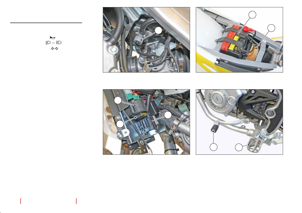
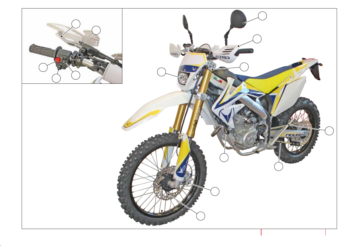
MAIN ELEMENTS
Main elements on the left side
1. Left rear view mirror.
2. Buzzer button “
3. Light switch “
4. Blinker switch “
5. Buzzer
6. Airlter
7. Cold-start device.
8. Fuse holder (main and secondary).
9. Clutch lever.
10. Fuel tap (FUEL).
11. Clutch command lever.
12. Pilot’s left foothold (with spring, always
open).
13. Side kickstand.
14. Transmission chain.
15. Battery.
16. Contactor
17. Contactor fuse
18. Left handguard
19. Front brake pincers
20. Front brake disk
21. Front headlight
22. Front blinkers
”.
”.
”
16
17
10
15
6
8
11
12
10
use and maintenance manual
VENT 125 Baja + Baja RR / VENT 125 Derapage + Derapage RR
1
9
7
18
2
4
VENT 125 Baja + Baja RR / VENT 125 Derapage + Derapage RR
3
21
20
19
22
13
5
14
use and maintenance manual
11
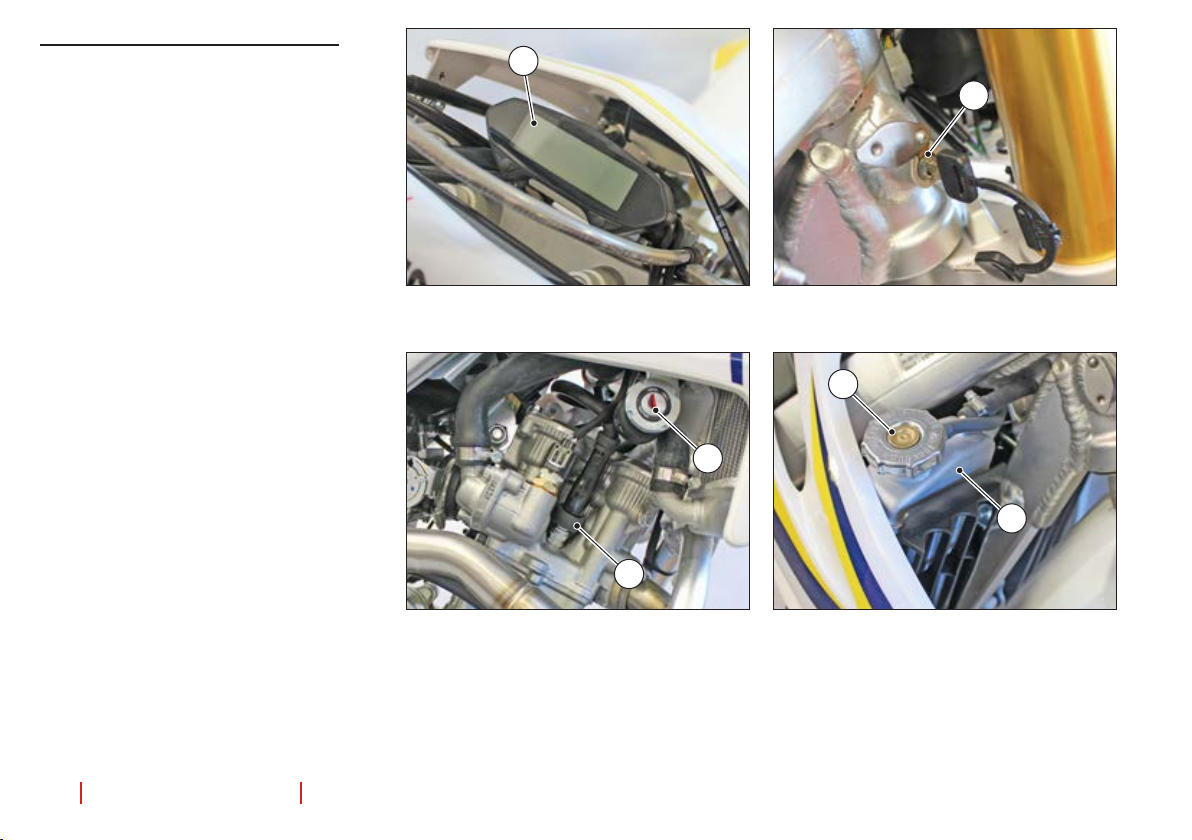
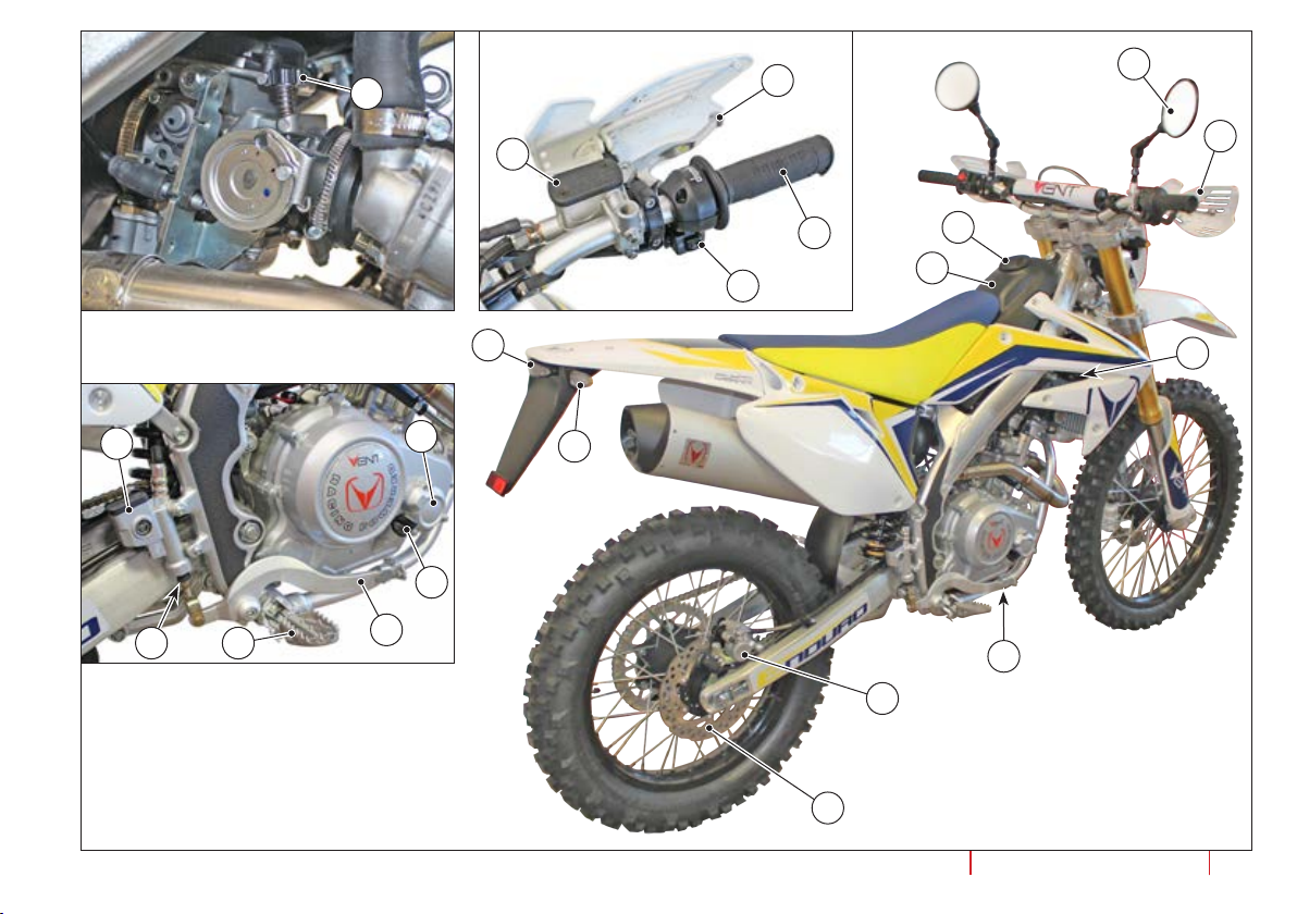
Main elements on the right side
1. Start and stop switch.
2. Right rear view mirror.
3. Fuel tank cap.
4. Fuel tank.
5. Coolinguidradiatorcap.
6. Coolinguidradiator.
7. Engine oil level rod-cap.
8. Engine oil drain plug.
9. Rear brake command lever.
10. Pilot’s right foothold (with spring,
always open).
11. Frontbrakeuidreservoir.
12. Front brake command lever.
13. Accelerator.
14. Dashboard.
15. Steering lock.
16. Spark plug.
17. Start button.
18. Rearbrakeuidreservoir.
19. Engineoilltercap.
20. Rear brake lever knob.
21. Engine idling speed knob.
22. Cooling fan.
23. Right handguard.
24. Rear brake pincers.
25. Rear brake disk.
26. Rear light/plate light.
27. Rear blinkers
14
15
5
1
6
16
12
use and maintenance manual
VENT 125 Baja + Baja RR / VENT 125 Derapage + Derapage RR
21
12
2
18
11
23
13
3
4
17
19
26
27
22
7
1020
9
8
24
VENT 125 Baja + Baja RR / VENT 125 Derapage + Derapage RR
25
use and maintenance manual
13
COMMANDS
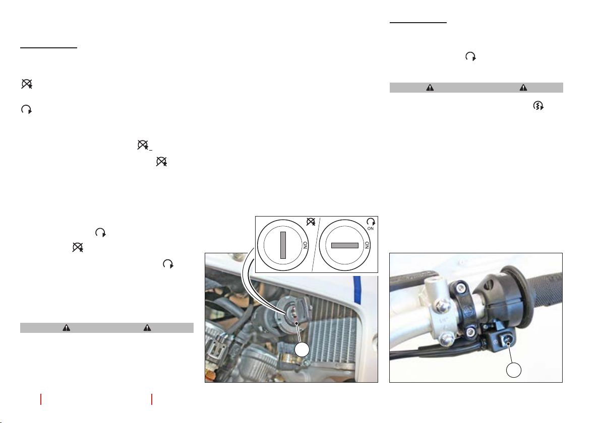
Start switch
The start switch has two positions:
“OFF” position, key removal;
“ON” position, motorbike start (key
cannot be removed);
might damage the engine and especially
cause loss of vehicle control, with possible serious consequences for people,
things and the vehicle itself.
Start button
Press the start button (1), with the start
switch at the ON “
will start.
Avoid pressing the start button “ ” (1)
when the engine is on: this might damage the starter.
” position, the engine
WARNING
- Key extraction position “
When the key is turned to the “
”
” position, the engine and the lights are turned
off and voltage is cut off from the circuits.
In this position, the key can be removed
from the switch.
- Start position “
From the “ ” OFF key removal position,
turn the key (1) clockwise to the “
”
” ON
position. The lights will light up and the
display will show that the circuits are live.
It is now possible to start the motorcycle.
DANGER
Do not tamper with the engine on/off
key (1) while the engine is running. This
would temporarily stop the engine and
then restart it when the key is used. This
14
use and maintenance manual
OFF OFF
OFF
1
For the engine start procedure, see the paragraph on “Starting the engine”.
1
VENT 125 Baja + Baja RR / VENT 125 Derapage + Derapage RR
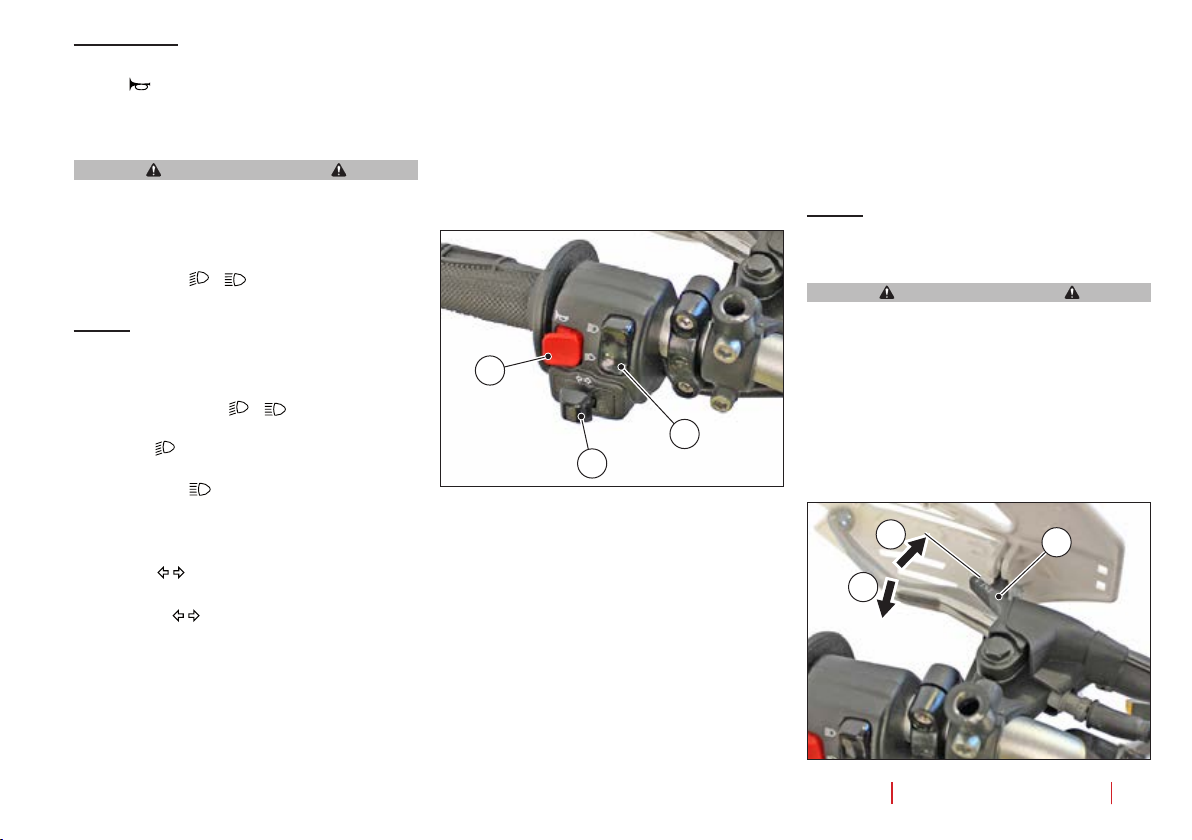
Left switch
Honk “ ”
Press the button (1) to honk.
WARNING
The use of the honk must be limited by
the laws of the road and to specic prohibitions.
Light switch “
NOTE: When the light switch is in “ON”
position, the passing and position lamp is
always switched on.
- The light switch “ - ” (2) has two positions.
In the “
are turned on.
In position “
lamp is switched on and the relative indicator lights up on the dashboard.
Blinkers “
The blinker “ ” (3) has three positions, re-
turning to the centre position.
- When moved to the right and released,
it turns on the right blinker. Its relative
warning light on the dashboard will turn
on;
- ”
”, position, the dipped beams
”, the driving and position
”
- When moved to the left and released,
it turns on the left blinker. Its relative
warning light on the dashboard will turn
on;
To turn off the blinker, press the lever (3)
once it is back in its central position.
1
2
3
Cold-start device
This vehicle is equipped with a cold-start
device commanded by a lever (1).
- To activate the cold-start device, turn the
lever (1) counter-clockwise (B) and keep
it in position.
- After starting the vehicle, wait a few seconds until the engine’s regime of rotations per minute is settled (this depends
on the room temperature). Turn off the
cold-start device by releasing the lever
and making sure it returns to the “A” position.
NOTE: Prior to starting the engine, make
sure the lever (1) is completely rotated
clockwise (A).
WARNING
ONLY use the cold-start device when
the engine is off and cold. NEVER use
it while the engine is running. Use the
cold-start device only when necessary.
A
1
B
VENT 125 Baja + Baja RR / VENT 125 Derapage + Derapage RR
use and maintenance manual
15
Clutch command
The command lever (1) for the clutch is located to the left of the steering wheel.
1
Accelerator command
The accelerator command (1) is located to
the right of the steering wheel.
According to how much it is turned, the
rotations per minute will increase or diminish.
1
Front brake command
The command lever (1) for the front brake
is located to the right of the steering wheel.
NOTE: The lever has a STOP switch: when
braking, it lights up the rear stop light.
1 2
Combined braking command
The motorcycle is equipped with combined
brakes.
- The command pedal (1) for the combined
braking is located on the right side of the
motorcycle.
NOTE: The pedal has a STOP switch:
when braking, it lights up the rear stop
light.
- Pull the lever (2) to brake with the front
brake;
- Press the pedal (1) for combined braking. The system will split the braking between the front and the rear brakes.
1
16
use and maintenance manual
VENT 125 Baja + Baja RR / VENT 125 Derapage + Derapage RR
Clutch command lever
This motorcycle is equipped with six gears.
- Use the lever (1) to change gears.
NOTE: After inserting a gear, release the
lever (1), which will return to its central
position.
WARNING
To change the gear, pull the gear lever
and lower the number of rpm using the
accelerator knob.
- From the N (neutral) position, press the
lever (1) downwards to insert the rst
gear.
- To change to the other gears, move the
lever (1) upwards.
- To reduce the gears, proceed in the opposite direction.
6
5
4
3
2
N
1
1
Steering lock
To lock the steering, do the following:
- Park the vehicle on its kickstand.
- Turn the handlebar completely to the left.
- Turn the protection cover (1).
- Insert the key (2) into the lock (3).
- Rotate the key (2) counter-clockwise.
- Press the key (2) inwards and turn it
clockwise.
- Remove the key.
To unlock the steering, follow the same instructions in the opposite order.
WARNING
Do not leave the key inserted after having unlocking the handlebar; when the
handlebar is turned, it may break the
key.
1
2
3
Fuel tap
This motorcycle is equipped with a screwing fuel tap (1).
- Completely closed (tightened), it closes
the feeding line of fuel to the carburettor;
- Completely open (unscrewed), it opens
the feeding line of fuel to the carburettor.
NOTE: Prior to starting the motorcycle,
make sure the tap (1) is completely open
(unscrewed).
NOTE: It is advisable to close (tighten) the
tap (1) when the motorcycle is not to be
used for a few days.
WARNING
This vehicle is NOT equipped with manual fuel reserve. The use of the fuel reserve is automatic, and is indicated by
its specic warning light on the dashboard. When the fuel reserve light on the
dashboard lights up, ll up the tank as
soon as possible.
1
VENT 125 Baja + Baja RR / VENT 125 Derapage + Derapage RR
use and maintenance manual
17
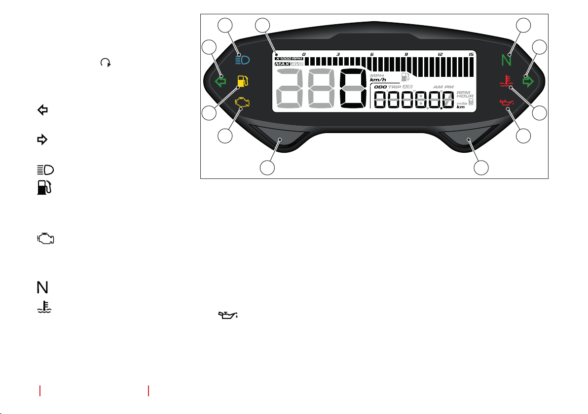
DASHBOARD
ODOMETER
The odometer is activated when the start key
is in the ON position.
Lights and buttons
1) Backlighted display
GREEN light, left blinker; it lights up
2)
when the left blinker is on.
3)
GREEN light, right blinker; it lights
up when the right blinker is on.
4)
BLUE light, high beams are on
4
1
2
5
6
10
11
7
3
8
9
5)
YELLOW light, fuel reserve.
This indicator lights up when the fuel
level is at its minimum. Drive to the
nearestfuelstationtollupthetank.
6)
YELLOW light; engine anomaly.
It lights up when an engine or exhaust
anomaly has happened. Go to the
nearest VENT Dealer.
7)
GREEN light, neutral gear.
8)
Cooling uid temperature alarm
light
18
use and maintenance manual
When the warning light is on, this
means the temperature of the cool-
ing
uid has reached its maximum
allowed temperature. Stop the vehicle, leave the engine at idle for a few
seconds, then turn it of
f. Wait until
the temperature of the cooling uid
drops then restart the engine. If the
light turns on again, do not use the
vehicle. Take it to the nearest VENT
Dealer.
9) Not used
10) Select button
Multi-function button. Pressing during
use will display, in sequence:
VENT 125 Baja + Baja RR / VENT 125 Derapage + Derapage RR
-
Start time (when the motorcycle is
turned off, the time will go back to zero)
- Battery voltage.
11)
Select button
Multi-function button. Pressing during
use will display, in sequence:
- Total km/miles
- Trip A
- Trip B
- Total hours running
- Trip A hours running
- Trip B hours running
- Maximum rotations per minute
achieved (optional)
- Maximum speed reached
- Average speed employed.

3
1
Display
1) Speedometer
Indicates the speed of the vehicle
2) Multidata display
This part of the display can show the
following information:
Odometer
- Total km/miles covered
- Maximum 99,999 km/miles; once this
maximum value has been reached,
the odometer resets itself and starts
counting from 0 again. Minimum: 1
km/mile
Partial “Trip A/B” km/mile counters
It is possible to set two partial counters,
Trip A and Trip B. Indicator of maximum
km/miles covered, maximum 9999.9
km/miles; once this maximum value has
been reached, the odometer resets itself
and starts counting from 0 again. Mini
mum: 0.1 km/mile
“Total” or partial running hours for
Trip A and Trip B
4
2
It is possible to set two partial counters,
Trip A and Trip B, and a Total hour counter.
Indicator of maximum hours covered,
maximum 9999.9 hours; once this maximum value has been reached, the odometer resets itself and starts counting from
0 again. Minimum: 0.1 hour
.
Indicator of total hours covered, maxi-
mum 99999.9 hours; once this maximum
value has been reached, the odometer
resets itself and starts counting from 0
again. Minimum: 0.1 hour
.
Maximum rpm achieved (optional,
with additional kit)
Maximum speed reached
Average speed employed
3) RPM indicator
(optional, with addition-
al kit)
4) Reserve fuel level indicator.
This indicator lights up when the fuel
level is at its minimum. Drive to the
nearestfuelstationtollupthetank.
1
Reset partial values
To reset the partial values Trip A, Trip B,
maximum rpm achieved, maximum speed
achieved, average speed covered, proceed
as follows:
- Press the “Set” (1) until the desired
screen is displayed, e.g. Trip A, then
press “Set” (1) again for 3 seconds to reset the value.
- Proceed in the same manner for all other
screens.
VENT 125 Baja + Baja RR / VENT 125 Derapage + Derapage RR
use and maintenance manual
19

INSTRUCTIONS TO USE THE
VEHICLE
General checks prior to use
Every time you are about to ride your motorcycle, go through this checklist:
- Rotate the start key to the ON position
and make sure the display lights up;
- Turn on the high beam and make sure its
warning light is on;
- Turn on the blinkers and make sure their
relative warning lights are on;
- Pull the front brake lever and press the
combined brake pedal; make sure the
rear stop light turns on;
- Check fuel and engine oil levels;
- Checkthebrakeuidlevelinitstank;
- Checkthecoolinguidlevel;
- Make sure the handlebar is working by
turning it all the way to the right and to
the left;
- Check pressure in the tyres;
- Make sure tension in the chain is adequate.
NOTE: For the inspection operations,
please consult their relative paragraphs.
Climbing on and off the vehicle
Pay attention to the instructions below.
They have the goal of keeping the pilot or
the passenger from falling from the vehicle
and/or the vehicle itself from toppling, which
would result in damages
to people, things and the vehicle itself.
- Only climb on and off the vehicle if you
have freedom of movement; your hands,
in particular, must not be holding objects,
such as helmet, gloves or glasses.
Climbing on the bike
- With the bike on the side kickstand, the
pilot must climb on the motorbike from
its left side, with both hands holding the
handlebar.
- Once the pilot is on the bike, lift the bike;
the side kickstand will automatically lift
as well.
DANGER
Make sure the side kickstand is fully lifted.
WARNING
Do not place the pilot’s or the passenger’s weight on the side kickstand.
NOTE: If you are unable to rest both your
feet on the ground on both sides of the bike,
rm your right foot on the ground and keep
the left one ready to offer support.
- The passenger must extract the rear
footrests and climb from the left side
of the bike, using the left footrest while
holding on to the pilot.
20 use and maintenance manual
VENT 125 Baja + Baja RR / VENT 125 Derapage + Derapage RR

Climbing off the bike
- First of all, the passenger must climb off the
left side of the bike, using the left footrest.
- Once on the ground, the passenger must
push the rear footrests back in.
- The pilotmustkeep his/herhands rmon
the handlebar and climb off the left side of
the motorcycle, resting his/her left foot on
the ground and lifting his/her right leg.
- Once on the ground, lower the kickstand
and make sure the motorcycle is resting
its weight on it (for kickstand operations,
please read the “Side kickstand” chapter).
Break-in
Breaking in is crucial for the proper working
and duration of the engine.
The break-in means the rst kilometres
covered.
During break-in, it is necessary to follow
certain rules to prepare the parts of the engine and of the vehicle itself for the maximum performance to be demanded later on
(after the break-in).
toexceed andnottostressinsufciently;in
both cases the engine and parts of the vehicle might suffer.
ITINERARIES Do not strain engine, brakes
and suspensions in mountain roads.
Give preference to roads with curves and
moderate hills, where the engine, the brakes
and the suspensions can alternate periods
under stress and periods with little or no
stress at all.
SPEED Always change the speed gradually, without sudden, complete accelerations.
Complete acceleration is allowed, but DO
NOT ride for long distances with the accelerator knob fully turned (full regime).
BRAKING New brake linings. In order to be
fully operative, the friction surface of brake
linings must be broken in, so it adheres
perfectly to the disk when braking. A good
break-in requires about 200 km (125 miles)
of urban distance. During this period, go for
longer braking distances and use the brake
lever with more intensity . Avoid sudden, long
brakes.
Adjusting rear-view mirrors
DANGER
Never ride the vehicle with the rear-view
mirrors rotated incorrectly.
Before you get going, always make sure
the mirrors are in their correct position
and adjusted accordingly.
- Climb on to the vehicle, to the pilot position.
- Use the joint (1) to regulate mirror height
(2) and the joint (3) to adjust inclination.
NOTE: Make sure you, as pilot, can properly see the rear part of the road from your
sitting position.
DANGER
Always adjust the mirrors with the motorcycle standing still.
Rules for a good break-in
These rules are only suggestions to help the
rider break in the motorcycle properly. Failing to follow them may not result in immedi-
NOTE: The rst 500 km (312 miles) are the
threshold of end of break-in, but only after
the rst 1,000 km (625 miles) do the vehicle’s best performances occur.
ate damage, but can have negative effects
on the performance of the engine and of the
different parts of the vehicle.
STRESS It is important to “stress” the engine and the other parts of the vehicle in an
The 500-km break-in threshold (312 miles)
requires carrying out the maintenance
operations dened for this distance.
appropriate manner. It is also important not
VENT 125 Baja + Baja RR / VENT 125 Derapage + Derapage RR
WARNING
1
1
2
2
3
3
use and maintenance manual
21

Placing the vehicle on the side
kickstand
This vehicle is only equipped with a side
kickstand.
- Hold the left handle and place your right
hand on the posterior part of the seat;
- Push the side kickstand (1) with your
right foot until it is fully extended;
- Keep the side kickstand in its extended
position, then incline the vehicle until the
kickstand is on the ground.
WARNING
Make sure the vehicle is stable.
- The rotation of the side kickstand (1)
must be free from obstacles.
DANGER
The side kickstand automatically goes
back to its place when the vehicle is
pulled up from its parking position to its
working position.
- Once you are sitting on the bike, use your
left foot to check the side kickstand and
make sure it is completely in its resting position again.
If it is not fully back in, go through the inspec-
tions indicated in the Maintenance chapter.
Fuelling
WARNING
For the type of fuel, tank capacity and
fuel reserve, please check the “Technical information” paragraph.
- Park the vehicle on its side kickstand;
- Unscrew and remove the cap (1) of the
fuel tank.
NOTE: If you are using a funnel or anything
of the kind, make sure it is perfectly clean
before use.
- Do not ll the tank to its maximum capacity; maximum fuel level must remain
beneath the lower edge (2) of the shaft.
- Afterllingup,closethefueltankcap(1)
again.
1
22
use and maintenance manual
1
VENT 125 Baja + Baja RR / VENT 125 Derapage + Derapage RR
MAX
2

Starting the engine
- Unlock the handlebar;
- Unlock or remove any additional anti-theft device installed;
- Climb on to the vehicle, to the pilot position.
NOTE: This vehicle is equipped with auto-
matic lights.
- Make sure the light switch (1) is in the
low beam position “ ”
- Make sure the fuel tap (2) is completely
open (unscrewed).
- Insert the key (3) and turn it to the ON
position “
- Pull the clutch lever (4).
-
Place the gear lever (5) in its neutral position; the display will show this symbol: .
- Lock at least one of the wheels using its
relative command.
”
NOTE: To start the engine, the gear lever
must be in its neutral position “ “ or in a
gear, with the clutch (4) lever pulled.
- Press the start button (6) without accelerating, then release it as soon as the
engine starts running.
WARNING
Avoid pressing the start button (6) when
the engine is running: this might damage the starter.
NOTE: To avoid excessive battery con-
sumption, do not keep the start button (6)
pressed for more than 5 seconds.
If the engine does not start within this pe-
riod, wait 10 seconds then press the start
button again.
Cold-start
When the surrounding temperature is too
low(aroundorbelow0°C),itcanbedifcult
tostarttheengineatrst.
- Prepare the motorcycle as indicated previously: before starting the engine, pull
the lever (7) of the cold-start device.
- Start the engine by pressing the start button (6).
- Release the lever (7) as soon as the engine starts running.
- If the idling speed is unstable, use the
accelerator knob (8) with small and frequent rotations, to warm up the engine
and obtain a constant idling speed.
4
1
2
VENT 125 Baja + Baja RR / VENT 125 Derapage + Derapage RR
3
7
N
5
use and maintenance manual
6
8
23

Starting the engine after a long time of
inactivity
If the vehicle has remained inactive for a
long period of time, starting the engine may
not be an easy task, as the fuel feeding circuit may be partially empty.
- It may be necessary to press the start
button(1)manytimesin orderto llthe
circuit again and allow the engine to start.
Starting the engine when it is ooded
After following the complete starting proce-
dureandobservingtheengineisooded:
- Press the start button (1) for a few seconds (so the engine runs empty) with the
accelerator knob (2) fully rotated.
- Completely release the accelerator knob
(2).
- Press the start button (1) without accelerating, then release it as soon as the
engine starts running.
2
1
On your way
DANGER
If you are travelling without a passenger,
make sure the passenger’s footrests are
closed. While riding, keep your hands
rmly on to the handlebar and your feet
on the footrests.
WARNING
Make sure the “ “ light goes off once
the engine is started. If this does not
happen, do not use the vehicle: take it to
the nearest dealer instead.
NOTE:
stop to ll up your tank as soon as possible.
- With the accelerator knob (2) released
- Inserttherstgearby pushingthegear
- Release the brakes activated during en-
If the display lights up this symbol “ ”,
and the engine at its idling speed, fully
activate the clutch lever (3).
lever (4) downward.
gine start.
3
DANGER
When leaving, releasing the clutch lever
too jerkily or quickly may cause the engine to stop and the vehicle to jib.
Do not accelerate jerkily or excessively while releasing the clutch lever; this
will keep the clutch from slitting and the
front wheel from coming off the ground.
- Slowly release the clutch lever (3), simultaneously accelerating by moderately rotating the accelerator knob (2).
The vehicle will begin to move forward.
- Increase speed by gradually rotating the
accelerator knob (2), without exceeding
the maximum speed limit and the suggested rpm.
- Change gears as indicated in the paragraph on “Gear lever”.
6
5
4
3
2
N
1
4
24
use and maintenance manual
VENT 125 Baja + Baja RR / VENT 125 Derapage + Derapage RR

OFF
WARNING
Change gears one at a time; stepping up
several gears at once may cause the engine to exceed its maximum power and
to overrev.
Before and during the “scaling up” from
one gear to another, always slow down,
releasing the accelerator to avoid overrevving.
Stopping the vehicle
- Release the accelerator knob (1), gradually activate the brakes and simultaneously “scale down” the gears to reduce
the speed.
- Pull the clutch lever (2) before fully stopping the vehicle, to keep the engine from
turning off.
- Place the gear lever (3) in its neutral position.
- Release the clutch lever (2).
- During a temporary stop, keep at least
one of the brakes activated.
1
Stopping the engine
- Stop the vehicle as indicated previously.
- Rotate the key (4) to the OFF position
“
” and remove it.
- Park the vehicle on its side kickstand as
described in its relative paragraph.
2
6
5
4
3
2
N
1
3
4
MAINTENANCE
DANGER
Danger of re or toxic fumes.
Never place ammable substances
(such as fuel, cooling uid, solvents etc)
near the electric parts.
Always wear suitable garments (working overalls) and working gloves, latex
gloves, protective goggles (or mask)
when doing the necessary maintenance
operations on the vehicle.
Preliminary operations
Before starting maintenance operations:
-
Turn off the engine;
- Wait until all overheated parts of the vehicle (engine, silencer etc) are down to
room temperature;
- Make sure the place has suitable ventilation and air circulation;
- Check the maintenance area (it must
not be dusty, dirty or occupied with other
components not involved in the operations or the vehicle);
- Make sure you have all the tools and
pieces of equipment you need for the
maintenance operations you must carry
out;
- Always wear suitable garments (working overalls) and working gloves, latex
gloves, protective goggles (or mask)
when doing the necessary maintenance
operations on the vehicle;
VENT 125 Baja + Baja RR / VENT 125 Derapage + Derapage RR
use and maintenance manual
25

- Make sure you have all spare parts and
uidsyou needforthemaintenanceoperations(e.g.brakelinings,oil,brakeu-
id,coolinguid).
DANGER
Always respect the torque for each
screw.
Before intervening on the vehicle:
- Check this manual for torque values and
ndatorquewrenchtoworkwith.
DANGER
If you cannot nd one, contact a VENT
Dealer.
DANGER
Never use your mouth to hold mechanical parts or to carry out interventions of
any kind.
The vehicle is made of inedible parts,
some of which are hazardous or toxic.
Things you should know
For maintenance interventions, assistance,
technical and non-technical consultancy,
contact a VENT Dealer. They will provide
you with accurate, friendly, up-to-date service in accordance with VENT’s specic
guidelines for your vehicle.
The FIRST SHEET refers to scheduled
maintenance, for users willing to do maintenance themselves. This sheet is called:
INTERVENTIONS TO BE MADE BY A
VENT DEALER (BUT CAN ALSO BE
CARRIED OUT BY THE USER).
DANGER
VENT refuses all liability, both civil and
criminal, for damage inected to people
and things deriving from maintenance
interventions carried out by the user.
The user must inform the VENT Dealer of
the maintenance operations carried out, so
as not to have them done twice.
Users unwilling or unable to carry out maintenance operations themselves should contact a VENT Dealer.
Even when the user has carried out all
maintenance operations, VENT advises a
road test at a VENT Dealer.
The SECOND SHEET for scheduled maintenance, for the exclusive use of VENT
Dealers, is called:
INTERVENTIONS TO BE CARRIED OUT
EXCLUSIVELY BY VENT Dealers.
The maintenance operations described in
this sheet require technical and updated
knowledge,andsometimesspecicequipment, only VENT Dealers possess.
DANGER
Do not attempt to carry out and do NOT
have third parties carry out the operations indicated in this sheet, as they may
result in damage to the vehicle.
NOTE: Carrying out schedule maintenance
operations does not mean you can forgo
the general check you should always per-
form before using the vehicle.
Maintenance has been purposefully di-
vided in two specic sheets
26 use and maintenance manual
VENT 125 Baja + Baja RR / VENT 125 Derapage + Derapage RR

Scheduled maintenance sheets
FIRST SCHEDULED MAINTENANCE
SHEET
INTERVENTIONS TO BE CARRIED OUT
BY THE VENT Dealer (BUT CAN ALSO BE
CARRIED OUT BY THE USER)
Key
➀ = check.
➁ = clean.
➂ = replace.
➃ = adjust.
➄ = lubricate.
NOTE: Carry out these procedures more
frequently if the vehicle is used in rainy or
dusty places, or in irregular roads.
(*) = Every 12 months:
(**) = Each tyre replacement
(***) = First replacement after 500 Km
then after each 2000 Km.
➂.
➃.
Components
Spark plug
Clutch command/ Clutch play
Airlter
Handlebar play
Swingarm fulcrum axis play/levers
Lights system
Coolinguid
Engine oil
Engineoillter
Engine idling speed
Wheel rims and spokes
Tyres
Tyre pressure
Transmission chain tension and lubrication
Swingarm protection skid and chain eye
Kickstand
Wearing of front and rear brake linings
(where present)
End of break-
in 500 km
(312 miles)
➀ ➁
Every 2,500 km
(1,560 miles) or
6 months
Every 1,000 km (625 miles): ➁ /
Every 2,500 km (1,560 miles): ➂
➀ ➃ ➀ ➃
➀ ➁ ➀ ➁ ➂
➀ ➃ ➀ ➃
➀ ➀
➀ ➀
➀ ➀
(***)
➂
➂
➂
---
➀ ➃ ➀ ➃
➀
(**)
➀
(**)
➀ ➀
➀ ➃ ➀ ➃
Every 500 km (312 mi):
➀ ➀ ➂ ➀ ➂
--- ---
---
➀ ➂
Every 5,000
km (3,120 mi)
or 12 months
---
---
---
---
---
---
➀ ➂
---
---
---
---
➀ ➂ ➃
➀
---
VENT 125 Baja + Baja RR / VENT 125 Derapage + Derapage RR
27use and maintenance manual

SECOND SCHEDULED MAINTENANCE
SHEET
INTERVENTIONS TO BE CARRIED OUT
EXCLUSIVELY BY THE VENT Dealer
Key
➀ = check.
➁ = clean.
➂ = replace.
➃ = adjust.
➄ = lubricate.
NOTE: Carry out these procedures more
frequently if the vehicle is used in rainy or
dusty places, or in irregular roads.
(*) = Every 12 months:
(**) = Each tyre replacement
➂.
➃.
Components
Rear damper
Transmission cables and commands
Wheel centring and spoke tension
Handlebar stem bearings and handlebar play
Wheel bearings
Brake disks
General functioning of the vehicle
Brakeuid
Coolinguid
Valve play
Bolt tightening
Final transmission (chain, crown, pinion)
Fuel tubes
Brake tubes
Clutch wear
End of break-
in 500 km
(312 miles)
---
Every 2,500 km
(1,560 miles) or
6 months
➀
➀ ➄ ➀ ➄
➃ ➃ ➃
➀ ➀
---
➀ ➀
➀ ➀ ➂
➀ ➀
➀
➀
--- ---
Every year:
Every 2 years:
➀ ➀
➀ ➁ ➃ ➄ ➀ ➁ ➃ ➄
---
---
---
➀
➀
➀
Every 5,000
km (3,120 mi)
or 12 months
---
---
---
---
---
➂
➂
➀ ➃
---
---
Every 4 years:
➂
Every 4 years:
➂
---
28 use and maintenance manual
VENT 125 Baja + Baja RR / VENT 125 Derapage + Derapage RR

PARTS REMOVAL
In order to carry out some of the maintenance operations/inspections, it is necessary to remove some parts of the vehicle.
Removing the seat
- Unscrew the screws (1) on the left and
right sides of the vehicle and recover the
spacers.
- Lift the seat (2) starting with its rear part
(A) and slide it towards the back of the
vehicle (B).
NOTE: When assembling the seat back,
the tabs (3) must be positioned internally to
the side panel in contact with the chassis.
- To reassemble the seat (2), place it on
the vehicle, press down on its central
part, then push it forward until it comes to
a complete stop.
NOTE: The seat must be hooked correctly
with the front (4) and central (5) hooks be-
neath the seat, with their relative seats (6)
and (7) on the vehicle.
- Screw back the screws (1) on both sides
of the vehicle.
Removing the left front conveyor
- Remove the seat as described in its relative paragraph.
- Unscrew the screws (1) and recover
1
2
A
B
3
5
4
the two spacers from the two (1a) lower
screws.
- Remove the conveyor (2).
1
2
1a
VENT 125 Baja + Baja RR / VENT 125 Derapage + Derapage RR
6
7
use and maintenance manual
29

Removing the wheels
WARNING
An inexperienced user may nd it dif-
cult and complex to disassemble and
reassemble the front wheel.
In case of need, contact a VENT Dealer.
If you do wish to do it yourself, follow
these instructions.
NOTE: When disassembling and reassembling the wheel, be careful not to damage
the brake tubes, disk and linings.
To disassemble and reassemble, wear
work gloves that ensure suitable protection
for ngers and hands.
Disassembling the front wheel
- Park the vehicle on the central support
kickstand, with the front wheel off the
ground.
- Have someone hold the vehicle by keeping the handlebar in its driving position.
-
A second operator can now loosen the
screw (1) that blocks the wheel pin and
unscrew the pin (2).
- Hold the front wheel and manually slide
out the wheel pin (2).
WARNING
Mark the spacers and keep them apart
so as not to invert their positions when
reassembling the wheel.
NOTE: Remove the wheel, carefully sliding
the disk from the brake fork.
Remove the wheel by sliding it forward.
WARNING
Do not activate the front brake after
removing the wheel, otherwise the
fork pistons can leave their seats and
cause braking uid to leak.
If this happens, contact a VENT Dealer.
Reassembling the front wheel
- Have someone hold the vehicle by
keeping the handlebar in its driving position.
- Moderately grease the outer seats of
the wheel hub.
- A second operator should position the
wheel beneath the parts of the fork, inserting the brake disk into the fork.
- Use grease on the wheel pin and slide
it completely with the spacer (3) into
the wheel hub (left side) and the spacer (4) (right side).
- Tighten the wheel pin (2).
Wheel pin torque: 80 Nm (8 kg/m).
- Remove the central kickstand.
- With the front brake lever activated,
press repeatedly on to the handlebar,
causing the swingarm to dip.
This will allow the swingarm parts to
settle appropriately.
- Park the vehicle on its kickstand.
- Tighten the screws (1) of the wheel pin
clamp (right side).
Wheel pin clamp screw torque: 10 Nm
(1.0 kgm).
DANGER
After reassembling, repeatedly activate the front brake lever and make
sure the braking system is functioning
properly.
1
2
4
3
30
use and maintenance manual
VENT 125 Baja + Baja RR / VENT 125 Derapage + Derapage RR

Disassembling the back wheel
- Park the vehicle on the central support
kickstand, with the back wheel off the
ground.
WARNING
Let the engine and the silencer to cool
down to room temperature before carrying out any of the next operations, to
avoid burns.
When disassembling and reassembling
the wheel, be careful not to damage the
speed sensor or the brake tubes, disk or
linings.
- Have someone support the vehicle.
- A second operator should unscrew the
screw nut (1), locking the wheel pin (1)
from the other side.
WARNING
Mark the spacers and keep them apart
so as not to invert their positions when
reassembling the wheel.
- Hold the rear wheel and manually slide
out the wheel pin (2).
- Remove the wheel towards the back,
carefully sliding the disk from the brake
fork.
WARNING
Do not activate the back brake after removing the wheel, otherwise the fork
pistons can leave their seats and cause
braking uid to leak.
If this happens, contact a VENT Dealer.
Reassembling the back wheel
- Moderately grease the outer seats of the
wheel hub.
- Make sure the hole (D) of the brake fork
support plate (3) is properly inserted in its
anti-rotation seat (E), on the inner part of
the right arm of the swingarm.
- Apply a small and uniform amount of
grease on the wheel pin (2).
- Insert the wheel, careful to centre the
disk on the brake fork and not to bump
into the speed sensor.
- Assemble the chain on the crown.
- Lift the wheel.
- Insert the wheel pin (2) into the bracket
(4) from the left side, assembling its relative spacer (6), and into the bracket (5)
from the left side, assembling its relative
spacers (7) and (8).
NOTE: Be careful and insert the brackets
(4) e (5) in their relative pins of the chain
adjustment screws.
Wheel pin torque: 90 Nm (9 kgm).
NOTE: Make sure tension in the chain is
adequate, if necessary.
7 8
5
1
6
2
4
D
- Lock the pin (2) and tighten the nut (1)
VENT 125 Baja + Baja RR / VENT 125 Derapage + Derapage RR
E 3
use and maintenance manual
31

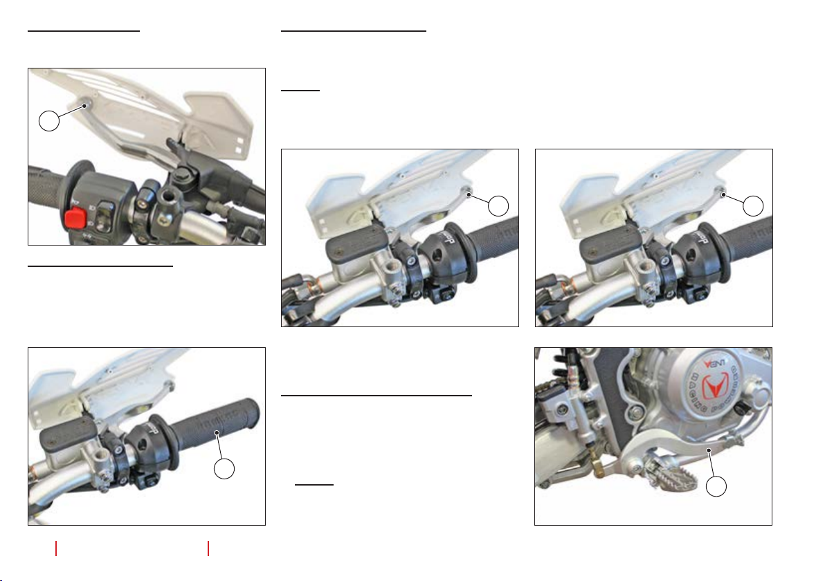
Disassembling the front light holder
- Park the vehicle on its kickstand.
Removing the lamp bracket Model Baja
- Unscrew and remove the screw (1). Repeat
the operation on the other side of the vehicle.
- Remove the lamp bracket (2) “A” and lift it
“B” to unhook it from the seats (3) of the front
mudguard.
WARNING
The lamp bracket, complete with front
headlight, remains connected to the
electric cables.
DO NOT FORCE THE ELECTRIC CABLES.
- Disconnect the electric connector (4)
from the light cable.
NOTE: Place the lamp bracket on a clean,
soft cloth on a support surface, to avoid
damage to the bracket.
Removing the lamp bracket Model
Derapage
1
- Unscrew and remove the screws (1). Repeat
the operation on the other side of the vehicle.
-
Remove the lamp bracket (2) from the support.
WARNING
The lamp bracket, complete with front
headlight, remains connected to the
electric cables.
DO NOT FORCE THE ELECTRIC CABLES.
- Disconnect the electric connector from
the light cable.
B
NOTE: Place the lamp bracket on a clean,
soft cloth on a support surface, to avoid
A
damage to the bracket.
- Re-mount everything, proceeding in the
opposite order to disassembly.
2
- Re-mount everything, proceeding in the
opposite order to disassembly.
32
use and maintenance manual
1
4
2
3
VENT 125 Baja + Baja RR / VENT 125 Derapage + Derapage RR

MIN
CHECKS
Engine oil level check
NOTE: The engine must be warmed up; the
check must be made after a trip or after 5
km (3 miles) in roads outside the city, suf-
cient to take oil temperature up.
- Park the vehicle on its kickstand.
- Stop the engine and let it cool down for at
least 10 minutes, to allow the oil to drain
into the housing and the oil itself to cool
down.
- Keep the vehicle in the upright position,
with both wheels touching the ground.
- Unscrew and remove the dipstick (1),
complete with its sealing ring (2).
WARNING
Check the sealing ring (2) for wear. Replace it if necessary.
- Use a clean cloth to clean the part that
comes into contact with the oil. Insert
the dipstick (1) completely in its seat (3),
without screwing it.
- Remove the dipstick (1) once again and
read the level visible on the stick:
MAX = maximum level
MIN = minimum level
- If the level visible on the stick is around
the MAX notch, it is correct.
WARNING
Do not ll over the MAX notch or below
the MIN notch, to avoid serious damage
to the engine.
- Ifnecessary,llup.
- Pour small amounts of oil into the oil
compartment (2) and wait about a minute before pouring some more. Do this
untiltheoilisowinguniformlywithinthe
housing.
- Checktheoillevelandcontinuellingup
if necessary.
- Screw and tighten the dipstick (1), complete with its sealing ring (2).
Dipstick (1) torque: 7 Nm (0.7 kg/m).
WARNING
Tighten the caps well and make sure no
oil is coming out.
Periodically check for oil leaks around
the housing lid seal.
NOTE: For instructions on changing the oil
and the lter, contact a VENT dealer.
1
2
3
MAX
VENT 125 Baja + Baja RR / VENT 125 Derapage + Derapage RR
use and maintenance manual
33

Brake uid level check
DANGER
Unexpected variations in the brake lever
play or elastic resistance on the brake
lever are caused by issues in the hydraulic system.
If normal inspections cannot be carried
out, of if you are in doubt regarding the
perfect functioning of the braking system, contact a VENT Dealer, which will
be ready to provide you with accurate,
friendly service.
DANGER
Be particularly sure that the brake disk
is not greasy or oily, especially after carrying out maintenance or inspections.
Make sure the brake tube is not twisted,
worn or cracked, cut or ssured in any
way.
NOTE: As the friction linings get worn, the
level of uid inside the reservoir diminishes,
to automatically compensate the wearing.
MIN = minimum level (Half of the inspec-
tion hatch)
- IftheuidisnotatorabovetheMINlevel
and the brake linings are not yet to be
replaced,llupthereservoir.
DANGER
For brake uid top-up, contact a VENT
dealer.
Rear brake uid level check
- Have someone hold the vehicle in its up-
rightposition, sothattheuidcontained
in the reservoir (1) is parallel with the
edge of the reservoir.
- Make sure the level contained in the reservoir is above the MIN notch.
MIN = minimum level (Half of the inspec-
tion hatch)
- IftheuidisnotatorabovetheMINlevel
and the brake linings are not yet to be
replaced,llupthereservoir.
DANGER
For brake uid top-up, contact a VENT
dealer.
1
Front brake uid level check
- Park the vehicle on its kickstand.
- Rotate the vehicle completely to the right,
sothattheuidcontainedinthereservoir
(1) is parallel with the edge of the reservoir.
- Make sure the level contained in the reservoir is above the MIN notch.
34
use and maintenance manual
1
MIN
MIN
VENT 125 Baja + Baja RR / VENT 125 Derapage + Derapage RR

ficacia frenante, la sicurezza e l’integrità
del disco sarebbero così compromesse.
Se lo spessore del materiale d’attrito (A)
[anche di una sola pastiglia anteri ore o po-
steriore] è ridotto sino al v alore di circa 1,5
mm (oppure se anche uno solo degli indi-
catori di usura non è più visibile):
Per la pinza freno anteriore. Fare sosti-
tuire entrambe le pastiglie della pinza
freno anteriore.
Per la pinza freno posteriore. Fare so-
stituire entrambe le pastiglie della pinza
Se utilizzato un imbuto o altro accesso-
rio, assicurarsi sia pulito.
Rabboccare con liquido refrigerante sino
a raggiungere il “livello di pieno”. (*1)
Se utilizzato un imbuto o altro accesso-
ficacia frenante, la sicurezza e l’integrità
del disco sarebbero così compromesse.
Se lo spessore del materiale d’attrito (A)
[anche di una sola pastiglia anteri ore o po-
steriore] è ridotto sino al v alore di circa 1,5
mm (oppure se anche uno solo degli indi-
catori di usura non è più visibile):
Per la pinza freno anteriore. Fare sosti-
tuire entrambe le pastiglie della pinza
freno anteriore.
Per la pinza freno posteriore. Fare so-
stituire entrambe le pastiglie della pinza
Brake lining check
- Park the vehicle on its kickstand.
NOTE: The brake fork comes with two
brake linings.
Visually inspect the area between brake
fork and linings, as follows:
- From above and from the front, for the
front brake fork (1);
- From above and from the back, for the
rear brake fork (2).
WARNING
If the friction material is worn beyond
acceptable limits, the metal support of
the lining might come into contact with
the disk, resulting in a metallic noise
and the formation of sparks against
the fork. The braking effectiveness, the
safety and the integrity of the disk would
therefore be compromised.
- If the thickness of the friction material (A)
(even if considering only one lining, either front or back) drops to about 1.5 mm
(or even if only one of the wearing indicators is no longer visible), it is necessary
to replace both linings.
DANGER
If this happens, contact a VENT Dealer.
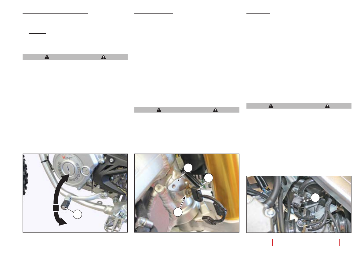
Cooling uid level check
DANGER
While the engine is warm, the cooling
uid is under pressure and at a high
temperature.
Risk of burns on the skin and damage
to clothes.
Remove the cap (1) ONLY after the engine has cooled down to room temperature.
- Switch the engine off and wait until it
cools down.
- Keep the vehicle in the upright position,
with both wheels touching the ground.
- Turn the handlebar to the left.
- Unscrew (A) (counter-clockwise) the cap
(1) until it locks into place (one-fourth of
a turn).
Wait a few seconds to allow any remain-
ing pressure to be released.
- Press the cap (1) downwards (B), unscrew it completely (C) (counter-clockwise) and remove it (D).
- Make sure the cooling uid reaches its
maximum level (2). If the level is not
reached, top it up without exceeding the
maximum level (2).
- Replace and tighten the cap (1).
VENT 125 Baja + Baja RR / VENT 125 Derapage + Derapage RR
2
1
A
2
2
B
3
3
use and maintenance manual
C
1
1
D
35

Checking the tyres
Check the status of all tyres, which must not
presentssures,abrasionsetc.Inaddition,
check the tread for wear, using the indicators on the tyres themselves.
Minimum tread height:
Baja - Baja RR = 4 mm
Derapage - Derapage RR = 2 mm
- Check the pressure while the tyres are
at room temperature, and follow the indications on the “Technical information”
paragraph.
WARNING
The front and rear tyres must be of the
same make and model. Using different
types of tyres on the same car compromises vehicle stability and manoeuvrability.
NOTE: Tyres get old even if they do not
look worn. Side cracks or deformations on
the carcass are signs of ageing; have a tyre
repairer check your tyres before using the
vehicle.
WARNING
Riding the motorbike with tyres lled
with an incorrect pressure or with worn
or deteriorated tyres may cause serious
injuries and even death after losing control of the vehicle.
36 use and maintenance manual
VENT 125 Baja + Baja RR / VENT 125 Derapage + Derapage RR

INSPECTIONS AND REGULATIONS
Side kickstand.
- Make sure the springs (1) are not damaged, worn, rusted or weakened.
The kickstand must be free to rotate.
Grease its joint (2) if necessary.
- Check the two little rubbers (3) that work
as limit switches for wear, in the case
of motorbikes equipped with passenger
footrests.
3
2
Handlebar
Check the rotation
The handlebar has bearings that allow for
minimum play, which must be inspected periodically.
- Climb on to the vehicle, to the pilot position.
- Rotate the handlebar completely to both
directions.
NOTE: Make sure the handlebar can rotate
in a uid manner, without obstacles or noises.
The handlebar must be neither too hard nor
too loose.
DANGER
If you detect any functional anomaly or
if specialised intervention is required,
contact a VENT Dealer.
Checking the play
- Park the vehicle on the central support
kickstand, with the front wheel off the
ground.
- Have someone else keep the motorbike
still on the central kickstand, while the
other operator moderately shakes the
limber in the direction of the movement
(A).
DANGER
If the play detected is evident, contact a
VENT Dealer.
- Remove the central kickstand.
1
1
VENT 125 Baja + Baja RR / VENT 125 Derapage + Derapage RR
A
use and maintenance manual
37

Swingarm
Fuel tank cap
- Park the vehicle on the central support
kickstand, with the back wheel off the
ground.
- Have someone else keep the motorbike
still on the central kickstand, while the
other operator moderately shakes the
limber sideways (transversal do the direction of the movement) (B).
DANGER
If the play detected is evident, contact a
VENT Dealer.
- Remove the central kickstand.
B
Iftheoriceonthefueltankcapisobstructed, fuel aspiration may be compromised,
which would hamper the start and the performance of your vehicle.
Periodically check the status of the fuel tank
cap.
- Park the vehicle on its kickstand.
- Unscrew and remove the fuel tank cap
(1).
- Check the status of the seal (2) on the
fuel cap.
If the seal is worn, replace the fuel cap.
DANGER
DO NOT use your mouth to check air
passage through the orice on the fuel
tank cap.
- Checktheorices(3)onthefuelcap.
Iftheoricesareobstructed,cleanthem
with compressed air.
- If cleaning is not enough, replace the fuel
tank cap.
1
3
2
38
use and maintenance manual
VENT 125 Baja + Baja RR / VENT 125 Derapage + Derapage RR

Air lter
WARNING
Do not wash or damp the ltration
element. DO NOT use woollen cloths
or any other “furry” material, to avoid
leaving residues on the air lter.
Do not use screwdrivers or any other
tools on the lter.
- Remove the battery as described in its
relative paragraph.
- Use a cloth to clean the inside of the
ltercasingbeforeremovingtheltration element, to keep dust and foreign
bodies from entering the suction collector.
- Unscrew the screw (1) as much as
necessarytoremovetheairlter.
- Remove the entire ltration element
(2), complete with screws (1).
- Remove thescrews(1) fromthelter
and recover the washer (1a).
- Holdtheairlterrmlyandhititseveral times against a clean cloth.
- If necessary, clean the air lter with
compressed air (make the air blow
from the inside towards the outside of
thelter).
- Cleantheouterpartofthelterwitha
clean cloth.
NOTE: While cleaning the ltration ele-
ment, check it for lacerations. If lacerated, replace it with one of the same kind.
- Use a cloth to clean the inside of the
lterbox.
WARNING
Do not apply oil or anything else on the
air lter.
- Replace the screws (1), complete with
washer(1a),intheairlter.
- Inserttheairlterintheltercasing.
- Manually screw and tighten the screws (1).
- Reassemble the battery.
1
2
2
1a
1
VENT 125 Baja + Baja RR / VENT 125 Derapage + Derapage RR
use and maintenance manual
39

Transmission chain
NOTE: The vehicle is equipped with a
chain of the chain link type. When disassembling and reassembling the chain,
make sure the spring (1) of the chain link is
installed with its open part turned to the op-
posite direction of the forward movement
direction (A).
WARNING
If the chain is too loose, it may slip out of
its pinion or crown, causing serious accidents or damage to the vehicle.
Periodically check the play “B” and, if necessary, adjust it.
To replace the chain of the pinion and the
crown, go to a VENT Dealer, where accurate service will be provided.
A
1
WARNING
Improper maintenance may cause early
wear of the chain and/or damage the pinion and/or the crown.
Carry out maintenance interventions
more often if you use the vehicle in
severe conditions or on dusty/muddy
roads.
Check the following parts and make sure
the chain, the pinion and the crown do not
present:
- Damaged rolls;
- Loose pins;
- Dry, rusted, smashed or jammed links;
- Excessive wear;
- Missing sealing rings;
- Excessively worn or damaged pinion or
crown teeth.
WARNING
If the chain rolls are damaged, the pins
are loose and/or the sealing rings are
damaged or missing, replace the entire
chain (pinion, crown and chain).
Wear thresholds for the components
Component Wear thresholds
Swingarm protection skid (2).
Complete wear of
the sliding track.
Chain eye (3). Complete wear of
the sliding track
Upper roll (4), lower roll (5).
Outer diameter of
the roll, minimum
27 mm.
4
2
5
B
40
use and maintenance manual
3
VENT 125 Baja + Baja RR / VENT 125 Derapage + Derapage RR

Lubrication and cleaning
NOTE: Lubricate the chain frequently, es-
pecially if you nd any parts that are dry or
rusty. Smashed or jammed links must be
lubricated and returned to proper work conditions.
If this is not possible, contact a VENT Deal-
er to have them replaced.
crown in the lower branch of the chain, is
of about 40 mm.
- Move the vehicle forward in order to
check the vertical oscillation of the chain
in other positions as well; the play must
remain constant in all the phases of
wheel rotation.
- If the play is uniform, but above or below
40 mm, adjust it.
- Tighten the right (3) and left (4) locknuts.
- Tighten the wheel nut (1), locking the
wheel pin (2) from the other side.
Wheel nut (1) torque: 90 Nm (9 kg/m).
- Check chain play.
Never wash the chain with water jets,
Chain tension regulation
steam jets, high-pressure water, and never
use highly ammable solvents.
- Loosen the wheel nut (1), locking the
- Clean the chain with special detergents
for OR-ring chains, then dry it with a
clean cloth.
- Lubricate the chain with a suitable spray
NOTE: For the centring of the back wheel,
there are reference notches (C) printed on
both tips of the swingarm arms.
lubricant for OR-ring chains.
- Loosen the right (3) and left (4) locknuts.
- Work on the right (5) and left (6) chain
WARNING
Never use grease to lubricate the chain.
Grease causes dust and mud buildups that work like abrasives, resulting
in quick wear of the chain, pinion and
crown.
On both sides of the vehicle, make sure
Play inspection.
- Turn off the engine.
- Park the vehicle on its kickstand.
- Place the gear lever in its neutral posi-
that the seat (D) present on the bracket
is properly coupled with the pin
(E) present at the head of the chain adjuster.
tion.
- Make sure the vertical oscillation (B), in
an intermediate point between pinion and
VENT 125 Baja + Baja RR / VENT 125 Derapage + Derapage RR
wheel pin (2) from the other side.
adjusters to regulate chain play. Make
sure the same references are used on
both sides of the vehicle.
WARNING
C
1
3
5
D
E
C
4
6
2
use and maintenance manual
41

Front suspension
- With the front brake lever activated,
press repeatedly on to the handlebar,
causing the swingarm to dip.
The stroke must be smooth and no trac-
es of oil must remain on the rods.
- Make sure all parts of the front suspension are tightened.
WARNING
If you detect any functional anomaly or
if specialised intervention is required,
contact a VENT dealer.
Rear suspension
- Have someone keep the vehicle in its upright position.
- A second operator must hold the rear of
thevehiclermly,pushingitdownandreleasing it a few times.
A) If the result is:
-Movementthatisnotveryuid;
- Metallic creaking;
- Perception of play;
WARNING
Contact a VENT dealer for an inspection.
WARNING
If you detect any functional anomaly or
if specialised intervention is required,
contact a VENT dealer.
Spring pre-load regulation
(Baja RR - Derapage RR)
WARNING
Possible risk of burns, including serious ones. Before working on the ferrule, wait until the engine has completely cooled down, as well as the
exhaust silencer
.
The basic setting of the suspension is
regulated by VENT to full ideal driving
conditions [pilot only (weighing around 70
kg)].
For different needs, personalise the setting according to the table below.
WARNING
Adjust spring pre-load according to
the conditions of use of the vehicle.
DANGER
Sports settings are advised for races or sports events, intended to take
place in circuits away from normal
road trafc.
- Loosen the grub screw (2).
- Use the regulation ferrule (1) to adjust
spring pre-load.
- Once the adjustment has been completed, tighten the grub screw (2).
2
1
- Make sure all parts of the rear suspension are tightened.
42
use and maintenance manual
VENT 125 Baja + Baja RR / VENT 125 Derapage + Derapage RR

Spark plug
Periodically disassemble the spark plug,
clear it from all carbon residues and replace
it if necessary.
WARNING
Before moving on to the next operations, allow the engine and the silencer
to cool down to room temperature, to
avoid the risk of burns.
- From the right side, remove the boot (1)
from the spark plug (2).
- Remove all traces of dirt from the base of
the spark plug.
- Unscrew the spark plug (2) and remove
it from its seat, being careful not to allow
dust or other substances inside the cylinder.
- Make sure the electrodes and the insulation of the spark plug contain no carbon deposits or signs of corrosion. Clean
them with compressed air if necessary.
NOTE: If the spark plug presents cracks on
the insulation (4), rusted electrodes (3) and
(5), excessive deposits or central electrode
(3) with its tip rounded (6), it must be re-
placed.
WARNING
When replacing the spark plug, use only
new ones of the type advised (see paragraph “Technical information”), otherwise engine performance and duration
may suffer.
- Check the distance between the electrodes using a thickness gauge.
The distance between the electrodes (1)
must be 0.8 mm. Adjust it if necessary,
carefully bending the side electrode (5).
- Make sure the washer (7) is in good conditions.
- To reassemble the spark plug, screw it
gradually all the way to the limit switch,
to avoid damaging its thread.
- Use a wrench to tighten it; turn 1/2 for the
plug to compress the washer.
Spark plug coupling torque: 23 Nm (2.3
kg/m).
- Insert the boot (1) correctly in the spark
plug (2) until you hear a click.
1
2
VENT 125 Baja + Baja RR / VENT 125 Derapage + Derapage RR
A
6
4 3
5
2
use and maintenance manual
43

Front brake command lever
The lever is ergonomically positioned during vehicle assembly.
- The position of the lever on the handlebar
can be adjusted downwards or upwards
bylooseningthetwoxatingscrews(1).
On reaching the desired tension, tighten
the screws (1).
If necessary, lever play can be adjusted as
well.
NOTE: Play and strike are directly proportional. When play is increased, so is the
strike, and vice versa.
- To adjust play, use the grub screw on the
front brake command lever (2).
- For the regulation, loosen the nut (3).
To increase play:
Loosen the grub screw (2).
To reduce play:
Tighten the grub screw (2).
- After regulation, keep the grub screw (2)
in position and tighten the nut (3).
DANGER
After regulation, make sure the wheel
turns freely when the brake is released.
Check the brakes for effectiveness.
In case of need, contact a VENT Dealer.
Combined braking command lever
The brake lever is ergonomically positioned
during vehicle assembly.
NOTE: The play of the rear brake command
lever cannot be adjusted.
If necessary, it is possible to personalise the
height of the brake lever.
DANGER
DO NOT unscrew the pump command
rod (2) completely.
Make sure the pump command rod (2) is
always visible within the swingarm (4).
If necessary, screw again the pump command rod (2).
- Keep the pump command rod (2) in position and tighten the locknut (3).
DANGER
After regulation, make sure the wheel
turns freely when the brake is released.
Check the brakes for effectiveness.
In case of need, contact a VENT Dealer.
44
use and maintenance manual
- Park the vehicle on its kickstand.
3
2
- Loosen the locknut (1).
- Screw or unscrew the pump command
rod (2) using the nut (3) until you obtain
2
3
1
the desired brake command lever height.
4
1
VENT 125 Baja + Baja RR / VENT 125 Derapage + Derapage RR

Clutch command lever
The lever is ergonomically positioned during vehicle assembly.
Adjusting the position
The position of the clutch lever on the handlebar can be adjusted downwards or up-
wardsbylooseningthexatingscrews(1).
On reaching the desired tension, tighten the
screws (1).
Clutch regulation
Adjust the clutch if:
- When the clutch lever is activated and a
gear is inserted, the vehicle moves forwards (the clutch does not detach);
- During acceleration, the engine improperly increases the rotations per minute
and there is a delay in the transferring
of motion to the rear wheel (the clutch is
jammed and, as a consequence, skids).
Checking for proper regulation
- Start the engine.
- Completely activate the clutch lever, in-
sert the rst gearandmakesurewhen
the clutch lever is released, the vehicle
moves uidly,withoutpresentinganyof
the defects described above.
WARNING
If it is not possible to obtain proper
clutch regulation or if the clutch is working irregularly, contact a VENT Dealer.
NOTE: Check the integrity of the clutch ca-
ble all over its length. The sheath must not
present ssures, cuts, squashed points or
signs of wear. If even one of these defects
is identied, have the clutch cable replaced
by a VENT dealer.
- Periodically lubricate the clutch cable
with a suitable lubricant.
A
1
2
4
Proceed as follows to adjust:
- Park the vehicle on its kickstand.
- Move away the protection casing (2).
- Loosen the ferrule (3).
- Rotate the grub screw (4) until the empty
strike (A) of the clutch lever, controlled at
the tip of the lever, is about 3-4 mm.
- Keep the grub screw in position (4) and
tighten the ferrule (3), locking the grub
screw (4).
- Replace the protection casing (2).
VENT 125 Baja + Baja RR / VENT 125 Derapage + Derapage RR
3
use and maintenance manual
45

Accelerator command regulation
Idling speed regulation
The empty strike (A) of the accelerator knob
must be 2-3 mm, measured along the edge
of the knob itself.
Proceed as follows to adjust:
- Park the vehicle on its kickstand.
- Slide out the protection casing (1).
- Loosen the ferrule (2).
- Rotate the grub screw (3) in order to restore the prescribed value.
- Manually block the rotation of the grub
screw (3) and tighten the ferrule (2).
- Check the empty strike (A).
If the outcome is positive:
Replace the protection casing (1).
WARNING
After completing the adjustment, make
sure the rotation of the handlebar does
not hamper the idling speed of the engine and that the accelerator knob, once
released, automatically returns to its
rest position.
A
- Drive for a few kilometres until a normal
functioning operation is reached, then
stop the vehicle.
- Work on the regulation knob (1) located
on the carburettor (right side).
SCREWING (clockwise) the knob, the
number of rotations increases.
- UNSCREWING (counter-clockwise) the
knob, the number of rotations decreases.
- To check the proper functioning of the
idling speed and to make sure it remains
stable, accelerate and decelerate a few
times.
WARNING
In case of need, contact a VENT Dealer.
31 2
1
46
use and maintenance manual
VENT 125 Baja + Baja RR / VENT 125 Derapage + Derapage RR

Battery
The vehicle is equipped with no-maintenance battery that does not require checking electrolyte levels.
DANGER
Fire hazard.
Fuel and other ammable substances
should never be placed near the electric
parts.
Never invert the polarity of the battery
cables.
Battery removal
- Place the start switch on OFF to avoid
accidental short-circuits.
- Remove the seat.
- Move away the protection casing (1).
- Unscrew and remove the screw (2) from
the negative terminal (-) and move the
negative cable (3) to the side.
- Move away the protection casing (4).
- Unscrew and remove the screw (5) from
the positive terminal (+) and move the
positive cable (6) to the side.
- Unhook the two elastic bands (7) and (8).
- Firmly grasp the battery (9) and lift it to
remove it from its seat.
DANGER
Once removed, the battery must be put
in a safe place, away from the reach of
children.
Rest the battery on a at surface, in a
cool, dry place.
If the battery needs to be replaced:
- Replace the battery with one of the same
type (see paragraph on Technical Infor-
mation).
Reassembling the battery
- Position the master switch at “OFF”.
- Place the battery (9) in its seat, with the
terminals facing the front part of the vehicle.
- Connect the positive clamp (+) using the
screw (5).
- Connect the negative clamp (-) using the
screw (2).
- Apply neutral grease or Vaseline on the
terminals and clamps.
- Replace the protection casings (4) and
(1).
- Hook the two elastic bands (7) and (8).
- Reassemble the seat.
Checking and cleaning the terminals
- With the seat off and the master switch at
the OFF position.
- Move away the protection casings (1)
and (4).
- Make sure the cable terminals the the
screw clamps (2) and (5) of the battery
are in good conditions (and not corroded
or covered in deposits) and that they are
covered by neutral grease or Vaseline.
If the inspection proves the ensemble to be
ok, reassemble the seat.
If the inspection shows the need for maintenance:
- Remove the battery.
- Brush the cable terminals and the screw
terminals (2) and (5) of the battery with a
metal brush, to eliminate all traces of rust.
- Reassemble the battery.
7
8
7
5
8
4
2
VENT 125 Baja + Baja RR / VENT 125 Derapage + Derapage RR
1
3
use and maintenance manual
6
9
47

Long battery inactivity
- If the vehicle is to remain inactive for
more than a fortnight, the battery will
need recharging to keep it from going
through a sulphation process.
- During the winter months, or when the
vehicle remains unused, to avoid its
degradation remove the battery from the
vehicle and check its charge periodically
(about once a month).
- If the battery remains in the vehicle, disconnect the cables from the clamps.
Recharging the battery
- Remove the battery.
- Provide a suitable battery charger.
DANGER
Carefully read the instructions of use for
the battery charger.
During recharge, make sure the area is
well ventilated and avoid inhaling the
fumes released during the recharge.
Prepare the charger for the type of charge
desired (see table).
Type of
recharge
Normal 12 0.6 5-10
Quick 12 3.0 1
Voltage VTension
(A)
Time
(hours)
- Connect the battery to the charger.
- Turn on the charger.
After the recharging period:
- Unplug the charger.
- Disconnect the battery from the charger.
DANGER
Wait about 10 minutes after unplugging
the charger before installing the battery,
as the battery will release fumes for a
short while even after disconnection.
Fuses
WARNING
Do not repair detective fuses.
Never use fuses different than those
specied.
This might cause damages to the elec-
tric system or even re, in the event of a
short-circuit.
NOTE: When a fuse is frequently defective,
a short-circuit or an overload is likely to
have taken place.
If this happens, contact a VENT Dealer.
If an electric part is found to be missing or
is working irregularly, or if the engine fails to
start, check the fuses.
Control and/or replacement of fuses
WARNING
Remove one fuse at a time, to avoid misplacing them.
Make sure the fuse presents:
- intactlament;
- proper assembly.
Ifthelamentisinterrupted:
WARNING
Before replacing the fuse, if possible, try
to identify the problem that caused this
inconvenience.
WARNING
Replace the fuse, if damaged, with another with the same amperage.
NOTE: If the spare fuse is used, remember
to insert an identical one in its seat.
48 use and maintenance manual
VENT 125 Baja + Baja RR / VENT 125 Derapage + Derapage RR

- T o access the fuses, remove the front left
conveyor, as described in its relative paragraph.
- Turn the start switch key to “OFF ”.
- Remove the lid (A) from the fuse box.
Fuse position
- fuse (1) 7.5 A: Cooling fan for the cooling
uidradiator;
- fuse (2) 5A: Switch for the front stop light,
switch for the rear stop light, dashboard,
control unit, intermittence of blinkers;
- fuse (3) 5A: Front lights, back lights, light
switch, buzzer;
- fuse (4) 15A: Start button (and starter),
light relays, clutch relay;
- fuse (5) 15A: Contactor (and consequently starter).
- fuse (6) 15A: Spare fuse.
After checking or replacing:
5
For a quick check of the proper orientation
of the front headlight:
- Placethevehicleonasolid,atterrain.
- Leave the vehicle 10 metres away from a
A
vertical wall.
- Climb on to the vehicle, to the pilot position.
- Turn the start switch key to “ON”.
- Make sure the headlight switch is in the
6
low beam position “ ”
- Make sure the light beam projected on
the wall is slightly below the horizontal
1
line of the projector (about 9/10 of the total height).
2
34
- If necessary, adjust it.
Also check:
- That the light beam is uniform;
- That no shadow areas are present.
- Replace the fuse in its own seat.
- Correctly replace the components re-
Light beam
moved to access the fuses.
Incorrectly adjusted beams may cause
accidents, including serious ones.
NOTE: Based on the laws in force in the
country where the vehicle is used, checks
on the orientation of the light beams require
specic procedures.
This is the Italian procedure.
VENT 125 Baja + Baja RR / VENT 125 Derapage + Derapage RR
DANGER
use and maintenance manual
49

Regulation of Model Baja
- Use a screw driver on the screw (1).
SCREWING (clockwise), the light beam
moves up.
UNSCREWING (counter-clockwise), the
light beam moves down.
- Screw or unscrew until you obtain the desired beam height.
1
Front headlight
Front headlight Model Derapage RR
The front headlight unit is LED. If it is not
working, the entire headlight unit must be
replaced. For this replacement, contact a
VENT Dealer.
Front headlight Model Baja - Baja RR Derapage
The front headlight contains:
- A parking light bulb (1);
- A high beam/low beam light bulb (2).
ACCESS TO THE LIGHT BULBS
Partially remove the front light bracket.
Reassembly
- Insert the light bulb in its socket, making
sure the two guiding pins match their
guides in the socket.
- Insert, press and rotate the bulb (1)
clockwise.
- Insert the light bulb socket (3) in the
headlight seat.
- Reassemble the front headlight.
Regulation of Model Derapage
- Partially remove the front headlight as
described in the paragraph “Front light
bracket disassembly”.
- Work on the two screws (2).
SCREWING (clockwise), the light beam
moves down.
UNSCREWING (counter-clockwise), the
light beam moves up.
2
50
use and maintenance manual
2
WARNING
The lamp bracket, complete with front
headlight, remains connected to the electric cables.
DO NOT FORCE THE ELECTRIC CABLES.
Parking light bulb
WARNING
To remove the light bracket, do not tug
on the power cables.
Disassembly
- Grip the light bracket (3), pull it and remove it from its seat.
- Press the light bulb (1) with moderate
strength and turn it counter-clockwise.
- Remove the light bulb (1) from its seat.
VENT 125 Baja + Baja RR / VENT 125 Derapage + Derapage RR
1
2
3
1

Low beam/high beam light bulb
Rear headlight bulb
WARNING
T o remove the electric connector, do not
tug on the power cables.
Disassembly
- Slide out the protection casing (4) of the
light bracket (5).
- Unhook the locking clip (6) of the light
bracket.
- Slide out the light bracket (5) from the
parabolic seat.
- Press the light bulb (2) with moderate
strength and turn it counter-clockwise.
- Remove the light bulb (2) from its seat.
Reassembly
- Insert the light bulb in its socket, making
sure the two guiding pins match their
guides in the socket.
- Insert, press and rotate the bulb (2)
clockwise.
- Insert the light bracket (5) in the parabolic seat, making sure (A) and the tip (B) of
the locking clip (6) are in the same position.
- Properly hook the locking clip (6) to the
light bracket.
- Slide the casing (4) properly.
- Reassemble the front headlight.
5
4
6
The rear headlight unit is LED. If it is not
working, the entire headlight unit must be
replaced. For this replacement, contact a
VENT Dealer.
Front and rear blinkers
The blinkers are powered by LED. If it is not
working, the entire headlight unit must be
replaced. For this replacement, contact a
VENT Dealer.
TRANSPORTATION
5
In the event of a breakdown, do not tow
the vehicle yourself. Request a profes-
2
sional towing service.
A
Before loading, remove or anchor to the
transportation surface (of the cart or
B
van) all objects that may be displaced
during transportation and crash against
the vehicle, therefore damaging it.
6
B
NOTE: The height of the transportation sur-
face (of the cart or van) requires the use
of a slide that allows for the loading of the
vehicle. The size, material and rigidity of
the slide must be sufcient to support the
weight of the vehicle during loading.
DANGER
WARNING
VENT 125 Baja + Baja RR / VENT 125 Derapage + Derapage RR
use and maintenance manual
51

- While loading the vehicle, get another
person to help you.
- Load the vehicle on the cart or van in its
normal moving position, with both wheels
touchingtheoor.
- Insert the rst gear and anchor the ve-
hicle to the oor by hooking the straps
on frame parts, handlebar etc, in such a
way as not to ruin plastic parts such as
conveyor sides and reservoir.
DANGER
Make sure the vehicle cannot move at
all, to ensure its stability during transportation.
CLEANING
Washing
It is advisable to periodically wash the vehicle, to maintain its components in good
conditions.
WARNING
Using in the following conditions requires more frequent washing, to protect its components:
- Seaside areas or places with a hot, damp
climate, where humidity and saltiness
are above average.
- Roads or areas where salt or chemicals
are used as anti-freeze.
- Roads or areas with the presence of industrial dust or asphalt spots.
52 use and maintenance manual
- Sports and off-road use.
- When the body of the vehicle is spotted
with dead insects, bird droppings etc.
WARNING
Avoid parking or lounging beneath
plants or trees.
During some seasons, certain plants
and trees drop or release residues, resin, fruits or leaves containing substances
that can damage the vehicle (especially
its body).
Washing rules
WARNING
Do not wash the vehicle under the sun,
especially during summer, while the
body of the vehicle is still hot. If the detergent dries on its surface before it is
rinsed away, the painting may be damaged.
To clean the plastic parts of the vehicle, do not use liquids at temperatures
above 40° C.
Do not direct air or water at high pressure or steam jets on the following
parts:
- Wheel hubs;
- Commands on the left and right sides of
the handlebar;
- Bearings;
- Pumps and brake reservoirs;
- Instruments and indicators;
- Opening of the silencer or the exhaust;
- Steering lock;
- Radiatoraps;
- Fuel cap and any other caps;
- Headlights;
- Electrical connections;
- Stickers.
WARNING
Do not use alcohol, benzenes or solvents to clean the rubber or plastic parts
of the seat. Use only water
and a gentle soap.
NOTE: To clean ONLY the outer parts of
the engine, use a degreasing detergent
suitable for motorcycles, brushes and
cloths.
WARNING
Using high-pressure water jets can ruin
parts of the vehicle.
-
Use a low-pressure water jet to wet
the vehicle and, in particular, its soiled
parts.
- Use a soft cloth to rub all parts of the vehicle.
VENT 125 Baja + Baja RR / VENT 125 Derapage + Derapage RR

- Use a low-pressure water jet to rinse the
vehicle.
- Dry the vehicle with clean shammy leather.
STORAGE
Follow the precautions below to avoid the
effects deriving from not using the vehicle.
WARNING
Whenever a tyre remains in place for too
long resting on the ground, its properties are altered.
DANGER
Washing the vehicle can reduce braking
efciency.
- Dry the disks, then carefully and repeatedly test the brakes.
- Check all brake functions, referring to the
specicparagraph.
Polishing
WARNING
Only after accurately cleaning the vehicle should you proceed to polishing it
with silicone waxes.
Abrasive pastes ruin opaque paints.
DANGER
Never apply protective waxes on the
seat, as this would make it slippery and
therefore dangerous.
- Completely empty the fuel tank and the
carburettor.
- Remove the spark plug.
- Pour a teaspoon (about 5-10 cm3) of
two-stroke engine oil into the cylinder,
through the spark plug seat.
NOTE: Place a clean cloth on the cylinder,
near the spark plug seat, to protect against
oil splashes.
- Work on the start lever a few times, to
uniformly distribute the oil poured into the
cylinder.
- Reassemble the spark plug.
- Remove the battery.
- Wash and dry the vehicle.
- Apply was on the painted surfaces.
- Check tyre pressure.
- Park the vehicle in a non-heated place,
free of dampness, protected against sunlight and with as little temperature variation as possible.
- Wrap a plastic bag around the exhaust
outlet or silencer to keep humidity or dirt
from entering.
- Place the vehicle on a support so that
both tyres are lifted off the ground.
WARNING
Protecting the vehicle from dust will
make vehicle parts last longer and facilitate washing when the vehicle is to be
used again.
Avoid using plastic or waterproof materials which might cause humidity to accumulate, with consequent deterioration
of the parts.
- Cover the vehicle with a tarpaulin (made
of cotton, wool or another transpiring
mateiral) large enough to fully cover the
vehicle, without touching the ground.
When you decide to use the vehicle again:
- Uncover and wash the vehicle.
- Fill its fuel tank.
- Check its functions.
DANGER
Ride the vehicle for a few kilometres at
a moderate speed, in an area away from
heavy trafc.
VENT 125 Baja + Baja RR / VENT 125 Derapage + Derapage RR
53use and maintenance manual

TECHNICAL SPECIFICATIONS
Baja Baja RR Derapage
Derapage RR
DIMENSIONS Length (mm) 2160 2141 2080 2070
Width (mm) 820 830
Height (at the handlebar) (mm) 1170 1210 1141 1180
Height at the seat (mm) 875 900 850 870
Distance between axis (mm) 1395 1450 1395 1410
Minimum free height from the ground (mm) 320 310 283 270
Empty weight (kg) 106.5 102.5 108.5 104.5
Weight in running order (kg) (*) 113 109 115 111
MOTOR Type Single-cylinder, 4 strikes, 4 SOHC valves
Number of cylinders Single-cylinder, tipped forward.
Overall engine capacity 124.66 cm
3
Boring/stroke 52 mm/58.6 mm
Compression ratio 11.2: 1
Electric start-up
Engine rotations per minute at idle 1400 ± 150 min-1
Clutch Multi-disk in oil bath with cable command on the left side of
the handlebar
Cooling withuid
Exhaust system (catalytic)
54 use and maintenance manual
VENT 125 Baja + Baja RR / VENT 125 Derapage + Derapage RR

Baja Baja RR Derapage
Derapage RR
CAPACITY Fuel (including reserve) 6 6 6 6
Fuel reserve 2,5 2,5 2,5 2,5
Engine oil
- oil change 950 cm
-oilchangeandoillter 1000 cm
- when disassembling the engine 1150 cm
3
3
3
Coolinguid 0,8l (40% water + 60% anti-freeze with ethylene glycol)
Seats 2
Vehicle load:
- Pilot + luggage 90 kg
- Pilot + passenger + luggage 165 kg
GEAR Type 6-gear shift, pedal commend on the left side of the engine.
VENT 125 Baja + Baja RR / VENT 125 Derapage + Derapage RR
55use and maintenance manual

TRANSMISSION
Baja Baja RR Derapage
Size 428
Derapage RR
CHAIN
CARBURETTOR Number 1
Model CVK 39S ILK KEHIN
ø29
POWER SUPPLY Fuel Lead-free gasoline, 95 octanes
FRAME Material Steel Aluminium Steel Aluminium
Type Double-cradle perimeter with decomposable rear part
Handlebar inclination angle 27°
Trail 57 mm
SUSPENSIONS Front Hydraulic telescopic swingarm:
Ø 41 mm
advanced pin
UPSIDE-DOWN
Ø 41 mm
advanced pin
UPSIDE-DOWN
Travel 230 mm 260 mm 230 mm 260 mm
Rear Single hydraulic damper adjustable in spring pre-load
Travel 270 mm
56 use and maintenance manual
VENT 125 Baja + Baja RR / VENT 125 Derapage + Derapage RR

Baja Baja RR Derapage
Derapage RR
BRAkES Front WAVE disk
Ø 250 mm Ø 290 mm
Hydraulic transmission
Two-pistonoatingfork
Rear WAVE disk
Ø 220 mm
Hydraulic transmission
Single-pistonone-pieceoatingcalliper
WHEEL RIMS Type Aluminium alloy with tangential spokes
Front 21” 17”
Rear 18” 17”
TYRES Front 80/90 - 21” 100/80 - 17”
Pressure 130 kPa (1.3 bar) 140 kPa (1.4 bar)
Rear 110/80 - 18” 130/70 - 17”
Pressure 150 kPa (1.5 bar) 150 kPa (1.5 bar)
START UP Type Digital electronic with variable advance
VENT 125 Baja + Baja RR / VENT 125 Derapage + Derapage RR
57use and maintenance manual

Baja Baja RR Derapage
Derapage RR
SPARk PLUG Standard NGK BR9 ES
Electrode spark plug distance 0.8 mm
LIGHT BULBS Front parking light 12 V - T4W LED
Low beam/high beam 12 V - 35/35 W - S2 LED
Front blinkers light -- 12 V - LED
Rear blinkers light -- 12 V - LED
Rear parking light/plate light/stop light -- LED unit
58 use and maintenance manual
VENT 125 Baja + Baja RR / VENT 125 Derapage + Derapage RR

VENT thanks you for choosing its vehicles and invites you to:
- Follow the laws of the road;
- Avoid leaving the engine on when not necessary;
- Avoid making bothersome noises with the vehicle;
- Not dispose of oil, fuel and other polluting substances and components in the
environment;
- Respect nature.
VENT 125 Baja + Baja RR / VENT 125 Derapage + Derapage RR
59use and maintenance manual

VENT S.r.l.: Via alla cascata, 5/7
23815 - Introbio (LC) - Italy
VAT number: 03728030135 - it
60 use and maintenance manual
VENT 125 Baja + Baja RR / VENT 125 Derapage + Derapage RR
 Loading...