

Page 1
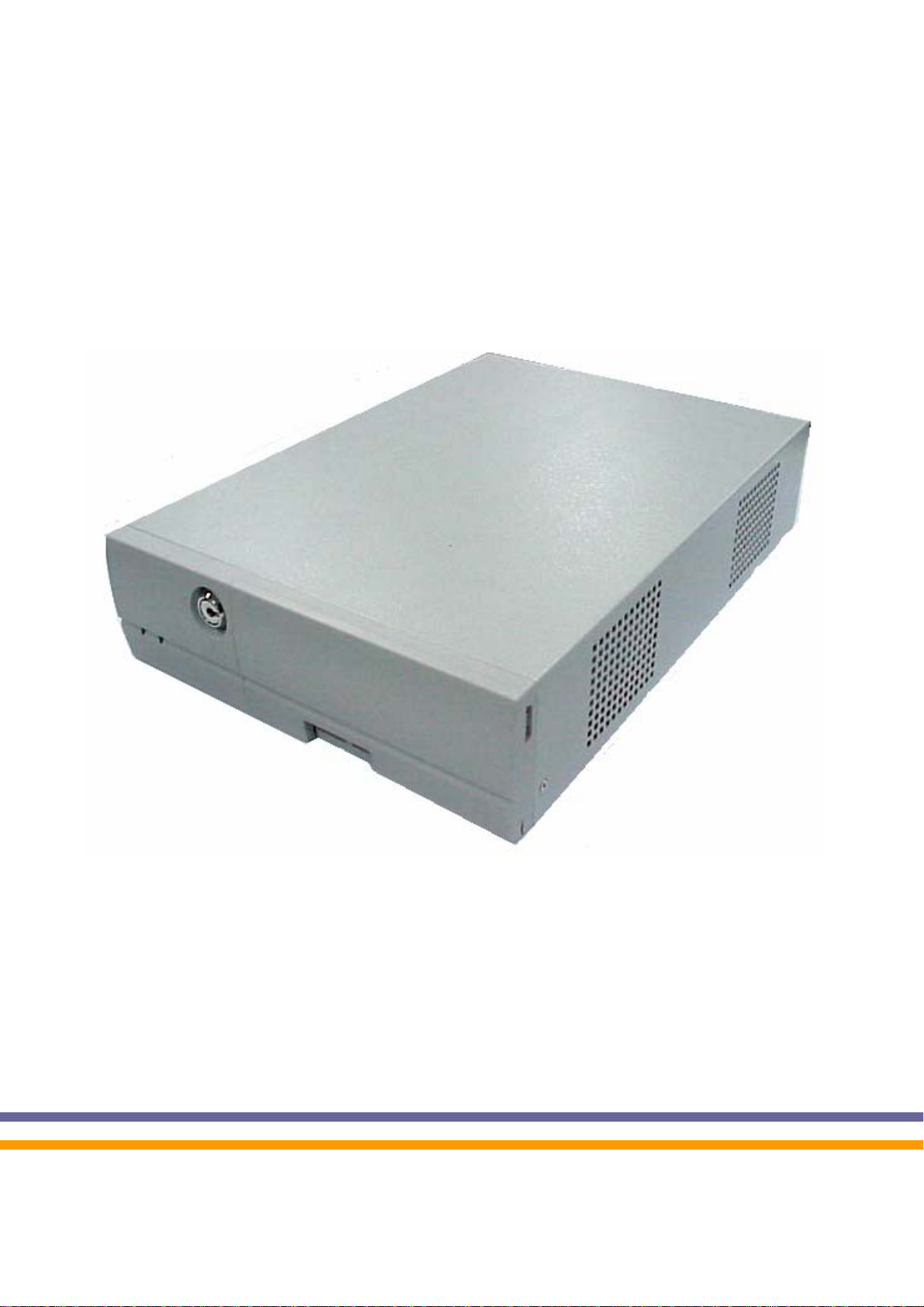
POS 4000
with B49 / B69 / B79
M/B Installation Guide
482000C1
Nov. 2004 V2.0
Page 2

Safety
IMPORTANT SAFETY INSTRUCTIONS
1. Read these instructions carefully.Save these instructions for future reference.
2. Follow all warnings and instructions marked on the product.
3. Do not use this product near water.
4. Do not place this product on an unstable cart, stand, or table.The product may fall,
causing serious damage to the product.
5. Slots and openings in the cabinet and the back or bottom are provided for ventilation;
to ensure reliable operation of the product and to protect it from overheating, these
openings must not be blocked or covered.The openings should never be blocked by
placing the product on a bed, sofa, rug, or other similar surface.This product should
never be placed near or over a radiator or heat register, or in a built-in installation
unless proper ventilation is provided.
6. This product should be operated from the type of power indicated on the marking
label.If you are not sure of the type of power available,consult your dealer or local
power company.
7. Do not allow anything to rest on the power cord.Do not locate this product where
persons will walk on the cord.
8. Never push objects of any kind into this product through cabinet slots as they may
touch dangerous voltage points or short out parts that could result in a fire or electric
shock.Never spill liquid of any kind on the product.
FCC
This device complies with part 15 of the FCC rules. Operation is subject to the following
two conditions: (1) This device may not cause harmful interference and
(2) This device must accept any interference received, including
interference that may cause undesired operation.
CD-ROM Safety Warning
DANGER
INVISIBLE RADIATION WHEN OPEN.
AVOID EXPOSURE TO BEAM
Caution on Lithium Batteries
Danger of explosion if battery is incorrectly replaced. Replace only with the same or
equivalent type recommended by the manufacturer. Discard used batteries according to
the manufacturer’s instructions.
/ 37
2
Page 3

Index
1. Accessory ...................................................................................................4
2. I/O Function................................................................................................5
2.1 POS 4000 Front View............................................................................5
2.2 POS 4000 Rear View.............................................................................6
3. Specification ...............................................................................................7
3.1 B69 & B79 .............................................................................................7
3.2 B49........................................................................................................9
3.3 System Memory Combination..............................................................11
4. Jumper Setting..........................................................................................12
4.1 B69 M/B...............................................................................................12
4.2 B79 M/B...............................................................................................14
4.4 POS I/O Board Jumper Setting............................................................18
5. Driver Installation......................................................................................19
5.1 B69 M/B...............................................................................................19
5.2 B79 M/B...............................................................................................23
5.3 B49 M/B...............................................................................................27
6.Installation the Cable Cover.......................................................................33
7. Installation Cash Drawer...........................................................................35
7.1 Cash Drawer Pin Assignment..............................................................35
7.2 Cash Drawer Controller register..........................................................35
7.3 Cash Drawer control command example.............................................36
8. Notices......................................................................................................37
8.1 Maximum dimension of Interface card.................................................37
8.2 Vertical position of POS 4000..............................................................37
/ 37
3
Page 4
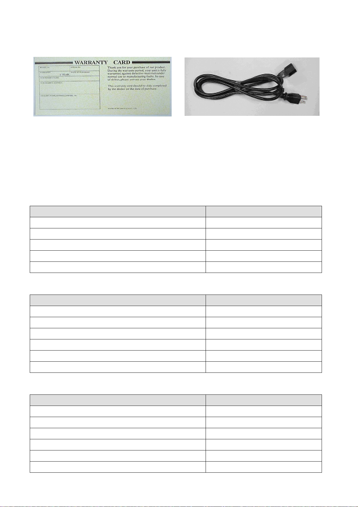
1. Accessory
a. Warranty Card b. Power Cable
c. Drivers Bank
d. Installation Guide
The following drivers in the folders of Driver Bank are necessary for driver installation.
B69 Mainboard
Folder/File File Description
<CD>:\B69\B69.htm B69 Driver list
<CD>:\Common\Ac97_codec\ADI\AD1881A Audio driver
<CD>:\Common\LAN_driver\R8139_810x LAN driver
<CD>:\Common\INTEL\Chipset Chipset driver
<CD>:\Common\INTEL\i815VGA VGA driver
B79 Mainboard
Folder/File File Description
<CD>:\B79\B79.htm B79 Driver list
<CD>:\Common\Ac97_codec\ADI\AD1881A Audio driver
<CD>:\Common\LAN_driver\R8139_810x LAN driver
<CD>:\Common\INTEL\Chipset Chipset driver
<CD>:\Common\INTEL\i845VGA VGA driver
<CD>:\Common\INTEL\USB20 USB2.0 driver
B49 Mainboard
Folder/File File Description
<CD>:\B49\B49.htm B49 Driver list
<CD>:\Common\VIA\Chipset
<CD>:\Common\VIA\VGA\CLE266 VGA driver
<CD>:\Common\LAN_driver\R8139_810x LAN driver
<CD>:\Common\Ac97_codec\Realtek\ALC202A Audio driver
<CD>:\Common\VIA\USB2.0 USB2.0 driver
/ 37
4
Chipset driver
Page 5
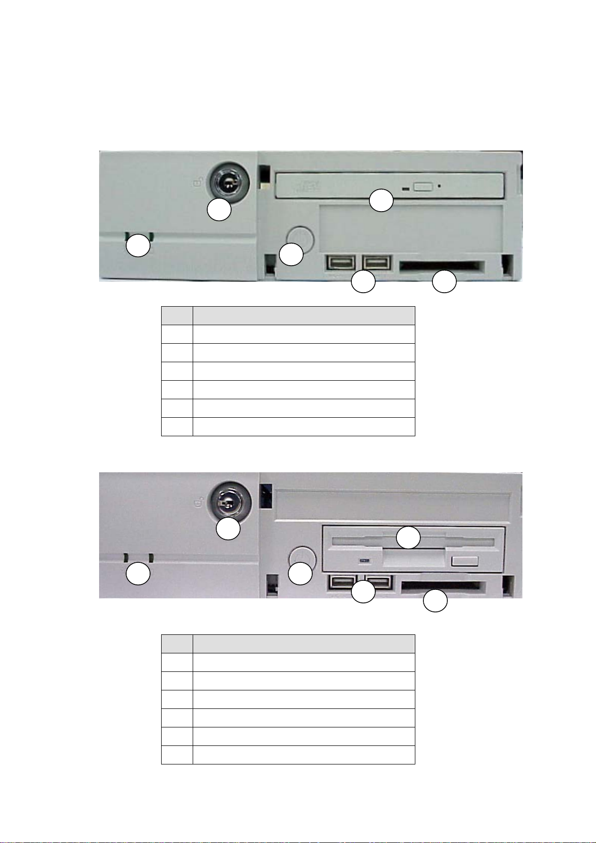
2. I/O Function
2.1 POS 4000 Front View
Optional 1:
Optional 2:
1
2
5
3
# Function
1 Power & HDD Indicator
2 Key Lock
3 Power Button
4 USB3 & 4
5 Slim CD-ROM
6 Compact Flash
6 4
2
1
# Function
1 Power & HDD Indicator
2 Key Lock
3 Power Button
4 USB3 & 4
5 Floppy Disc Drive
6 Compact Flash
3
4
5
6
/ 37
5
Page 6
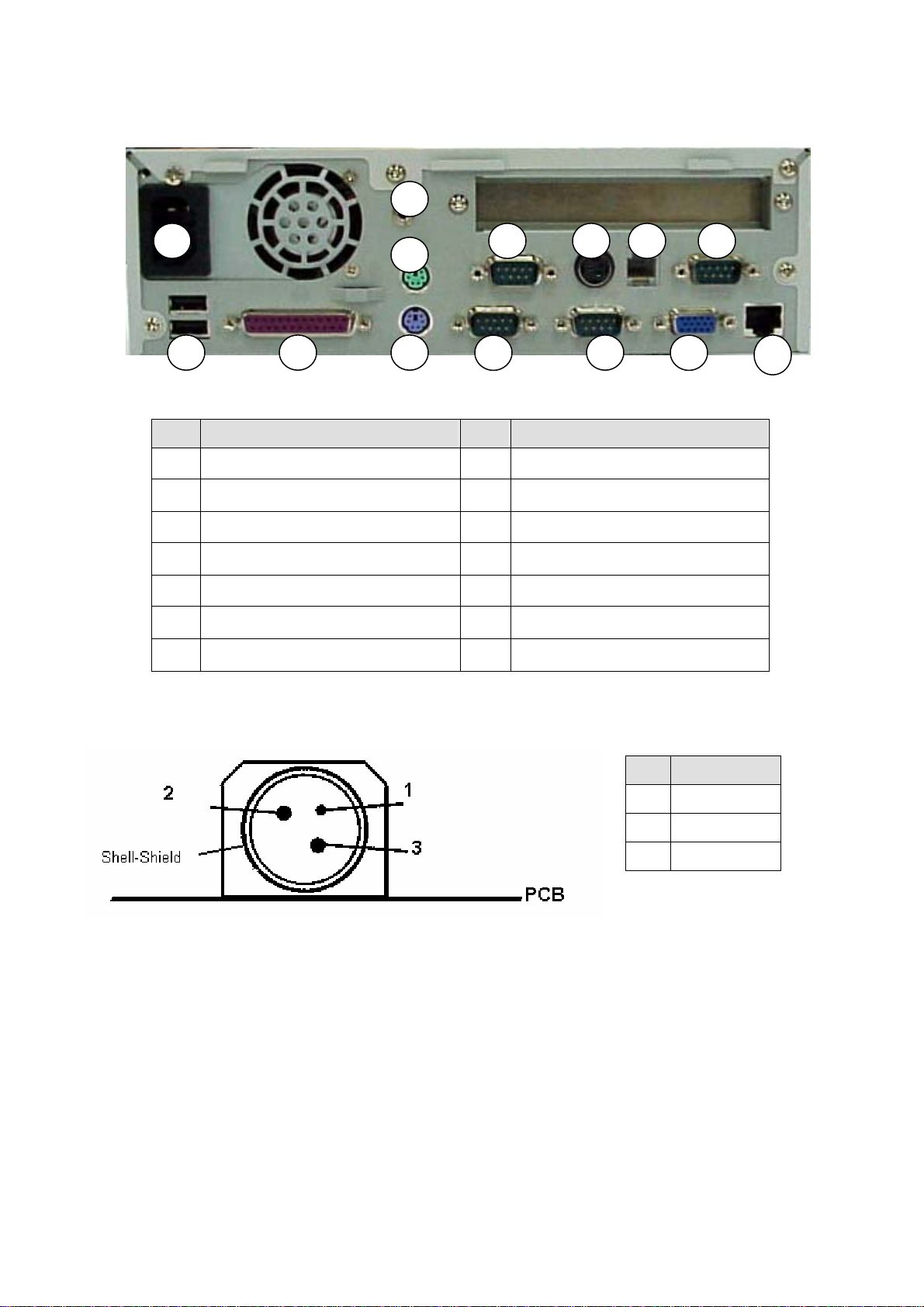
2.2 POS 4000 Rear View
20
7
# Function # Function
7 AC Inlet 14 VGA
8 USB 1 & 2 15 LAN
9 LPT 16 COM4
10 PS/2 Mouse 17 DC Output 24V/2.0A
11 PS/2 Keyboard 18 Cash drawer
12 COM2 19 COM3
13 COM1 20 Line out
10
11 139 8
16 17 18 19
12 14
15
Note: DC output 24 V Pin Assignment
Pin Assignment
1 NC
2 + 24V DC
3 Ground
/ 37
6
Page 7
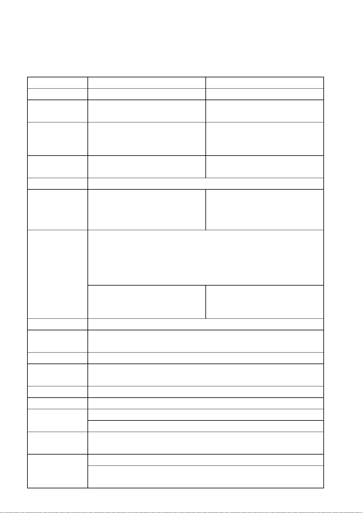
3. Specification
3.1 B69 & B79
Model
MB
Core logic
CPU
System memory
BIOS
VGA display
VGA memory
4691 4791
B69 all-in-one Mainboard B79 all-in-one Mainboard
Intel 82815E B-STEP GMCH &
82801BA ICH2
Intel socket 370 CPU Celeron /PIII
FC-PGA/FC-PGA2
2x 168pin DIMM sockets support
100/133 MHz SDRAM up to 512MB
Award PnP BIOS
BUILT-IN GMCH
Maximum resolution is up to
resolution of 1600x1200 pixels.
The internal graphics device use share system main memory structure
and supports Intel Dynamic Video Memory Technology (D.V.M.T.). Intel
D.V.M.T. dynamically r esponds to application requirements by allocating
Intel 82845GV GMCH & 820801DB
ICH4
Intel socket 478 CPU Celeron /P4
400/533 PSB with Hyper Threading
Technology support
2 x DDR DIMM 200/266/333 up to
2GB
Built-in GMCH
Maximum resolution is up to
resolution of 1920x1080 pixels.
I/O controller
LAN controller
IDE controller
HDD connector
FDD connector
Audio controller
Expansion Slot
Main board
the proper amount of display and texturing memory taken from system
memory by driver control.
1MB On-Chip Frame Buffer Size for
legacy OS.
W83627HF x 1, W83697 HF x1
Realtek RTL8100BL 10/100Mb fast Ethernet controller
Support WOL & boot from LAN
Built-in core logic support UDMA 33/66/100Mhz
Primary: 1x 40-pin 2.54 pitch
Secondary: 1x 44pin 2.0 pitch, 1x Compact Flash socket
1x 34-pin 2.54 pitch
AC’97 ADI AD1881A (2ch)
1x PCI slot
Optional: 1xISA slot
232x313mm
For legacy OS, user control the
1MB/8MB On-Chip Frame Buffer
Size by BIOS SETUP.
dimension
Storage Device
1 x 3.5” HDD drive bay
Optional:
1 x 3.5” FDD drive /(1 x slim CD-ROM /CD-RW/DVD-ROM drive bay)
/ 37
7
Page 8
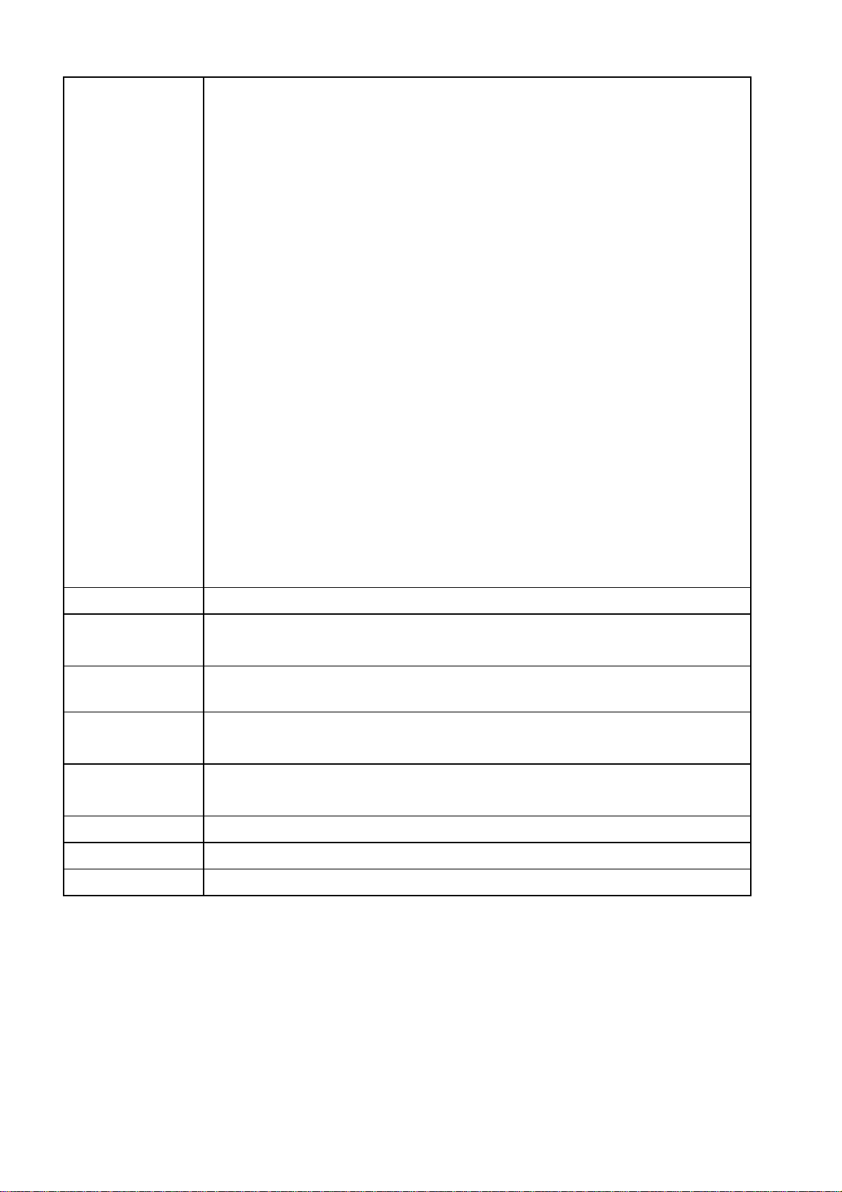
I/O Port
Rear Panel:
1 x PS2 keyboard port
1 x PS2 Mouse port
2 x DB-9M RS-232 serial ports
(COM1/COM2, pin1 & 9 with 5V/12V power select)
1 x DB25F Parallel port
1 x DB15F VGA port
1 x RJ45 LAN port
2 x USB ports
1 x Line out
POS I/O port
1 x RJ11 cash drawer port
1 x 24V POS printer power port (max. 24V/2A)
2 x DB-9M RS-232 serial ports
(COM3/COM4, pin1 & pin9 with 5V/12V power selectable)
Power Supply
System
Dimension
Thermal
Customer
Display
EMC
Safety
Case Color
OS Support
Front Panel:
1 x Compact Flash socket
2 x USB ports
FT8180 internal ATX 180W
240(w) x 335(d) x 72 (h) mm without cable manage cover
CPU Cooler x1
Support hardware monitor for fan speed control and software throttling
Optional: LED / VFD/ Graphic Customer Display
Pole height (9 / 22 cm)
FCC/CE Class B
CE mark: EN55022 / EN61000 -3-2 2000 / EN61000-3-3 / EN55024
LVD: EN60950 2000
Computer white/ Silver black
Win98/2000/XP/NT 4.0,Linux
/ 37
8
Page 9
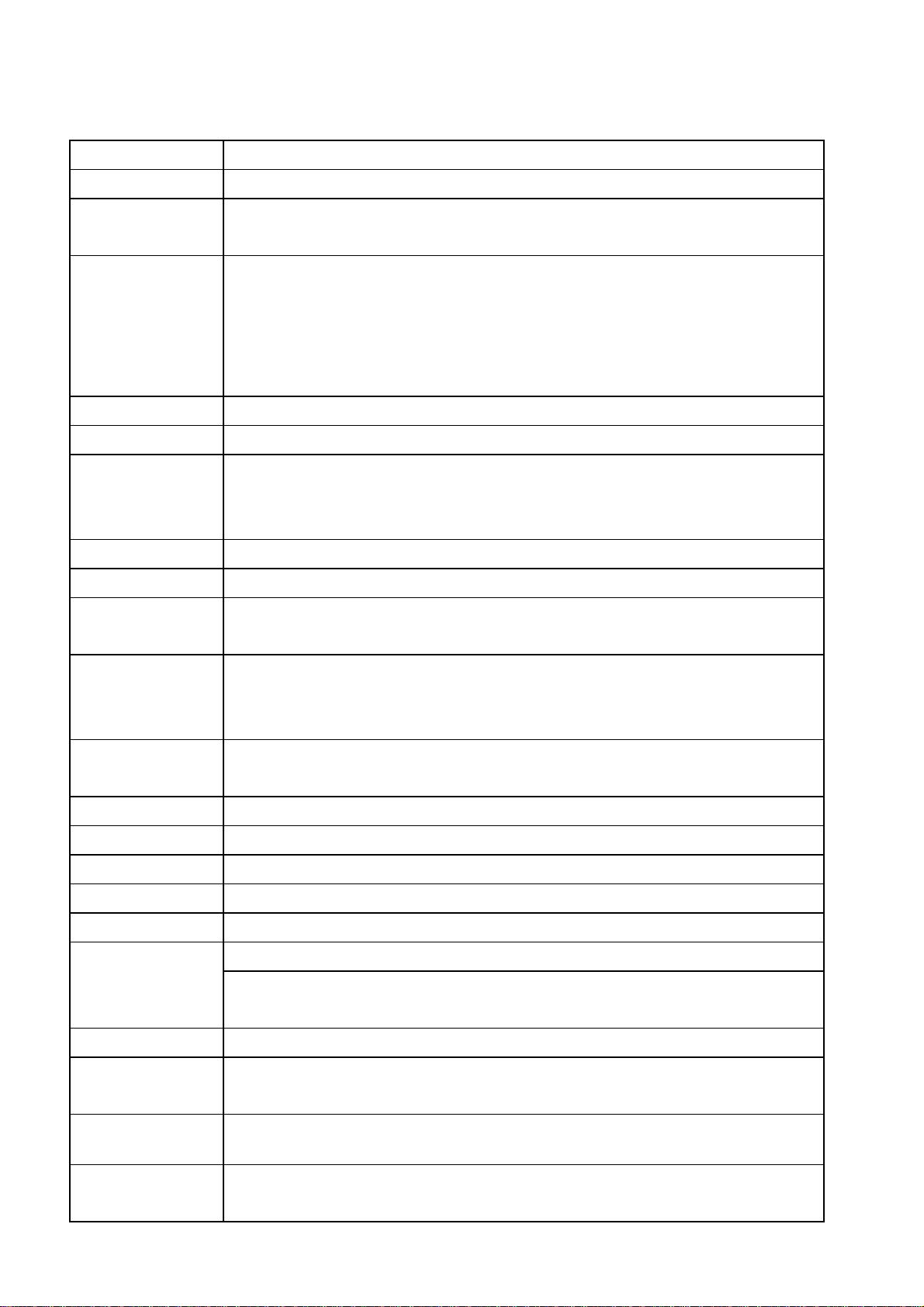
V
A
3.2 B49
Model
M/B
Core Logic
CPU
System Memory
BIOS
Video Display
ideo Memory
I/O Controller
4491
B49
VIA CLE266 (VT8623CE ) North Bridge
VIA VT8235CD South Bridge
VIA Eden / C3 EBGA Processors
Support for VIA C3 EBGA processors
133/100/66MHZ CPU Front Side BUS (FSB)
C3 EBGA 733 / 800 / 1.0G / 1.2G or High (Optional)
C3 EBGA 800 Standard to Use
2 x DDR266/200 DIMM up to 2Gbyte memory size
Award PnP BIOS
Integrated ProSavage8 2D/3D Video Accelerator
MPEG-2 video textures
2D/3D resolutions up to 1400 x 1050 x 32
16/32/64 MB frame buffer using system memory
Winbond 83697HFx1, 83697HFx1, 83697UFx1
LAN controller
TV – Out
HDD connector
FDD connector
USB Controller
udio controller
Expansion Slot
M/B dimension
Storage Device
Power supply
System
Realtek RT8100BL 10/100Mb fast Ethernet controller
Support Wake-On-LAN and boot from LAN
PAL / NTSC multi system support
VIA VT1622A TV Out (TV Encoder)
1 x 8pin-header support RCA /S-Video interface (Optional)
Primary: 1x 40-pin 2.54 pitch
Secondary: 1x 44pin 2.0 pitch, 1x Compact Flash socket
1x 34-pin 2.54 pitch
VT8235 Integrated support USB2.0
AC’97 Realtek ALC202A (2ch)
1 x PCI slot
232 mm (W) x 314 mm (D)
1 x 3.5” HDD drive bay
Optional:
1 x 3.5” FDD drive /(1 x slim CD-ROM /CD-RW/DVD-ROM drive bay)
FT8180 internal ATX 180W
240(w) x 335(d) x 72 (h) mm without cable manage cover
Dimension
Thermal
Customer
Display
CPU Cooler x1
Support hardware monitor for fan speed control and software throttling
Optional: LED / VFD/ Graphic Customer Display
Pole height (9 / 22 cm)
/ 37
9
Page 10

EMI
CE Class B
FCC Class B
I/O port
Rear Panel:
2 x USB 2.0 ports
1 x DB-25F Parallel port
1 x 1*6Pin Double PS2 Keyboard / Mouse port
2 x DB-9M RS-232 Serial port
1 x DB-15F VGA port
1 x RJ-45 LAN port
1 x Audio jacks: line-out
1 x Line out
POS I/O port
1 x RJ11 cash drawer port
1 x 24V POS printer power port (max. 24V/2A)
2 x DB-9M RS-232 serial ports
(COM3/COM4, pin1 & pin9 with 5V/12V power selectable)
Option1:
OS Support
1 x 2nd printer port on slot bracket
Option2:
2 x USB 2.0 ports (for slot user, support pin header)
Front Panel:
2 x USB 2.0 ports
1 x compact flash
Windows 9x/ME/NT 4.0/2000/XP
Linux
/ 37
10
Page 11
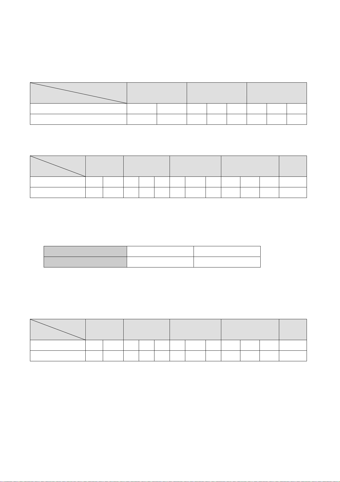
3.3 System Memory Combination
POS 4000 B69
RAM Size
128MB 256MB 512MB
Slot
DIMM1 X 128 128 256 X 256 512 X
DIMM2 128 X 128 X 256 256 X 512
POS 4000 B79
RAM Size
128MB 256MB 512MB 1024MB 2048MB
Slot
DIMM1 X 128 128 256 X 256 512 X 512 1024 X 1024
DIMM2 128 X 128 X 256 256 X 512 512 X 1024 1024
NOTE:
1. Optimal Combination
CPU system bus 400 533
DIMM DDR 266 DDR 333
2. In B79 memory 2048MB combination, if you want to use double stack memory that
your DIMM1 and DIMM2 all should be double stack memory.
POS 4000 B49
RAM Size
128MB 256MB 512MB 1024MB 2048MB
Slot
DIMM1 X 128 128 256 X 256 512 X 512 1024 X 1024
DIMM2 128 X 128 X 256 256 X 512 512 X 1024 1024
/ 37
11
Page 12
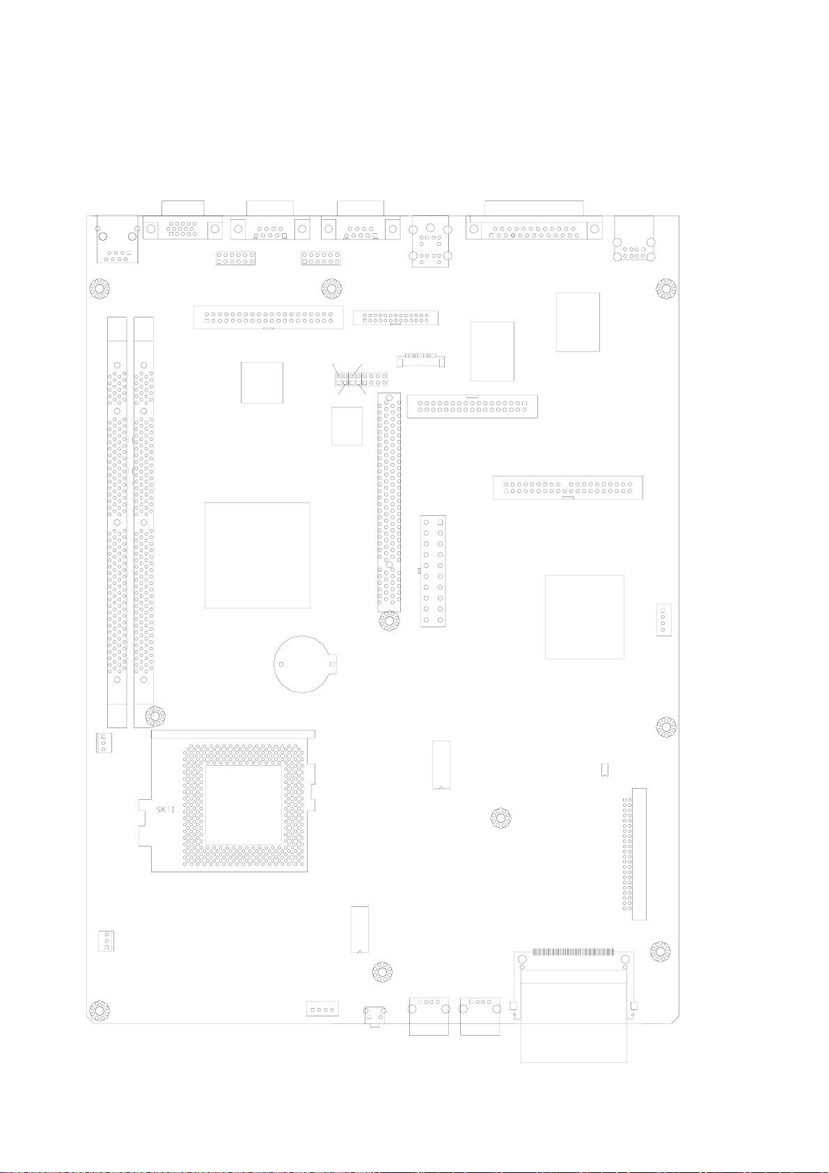
4. Jumper Setting
4.1 B69 M/B
RJ45-1
DIMM1
DIMM2
VGA1
COM1 COM2
JP1
DATA1
U11
U46
PRN1
PS1
JP2
CN1
U8
JP7
JP3
JP5
JP4
JP6
U14
CN4
CN2
U7
FDD1
IDE2
PWR1
USB1
CN5
FAS_CPU1
FAS_SYS1
BAT4
CN9
U49
SW1
U45
U47
U24
IDE3
CN6
USB2
USB3
/ 37
12
Page 13
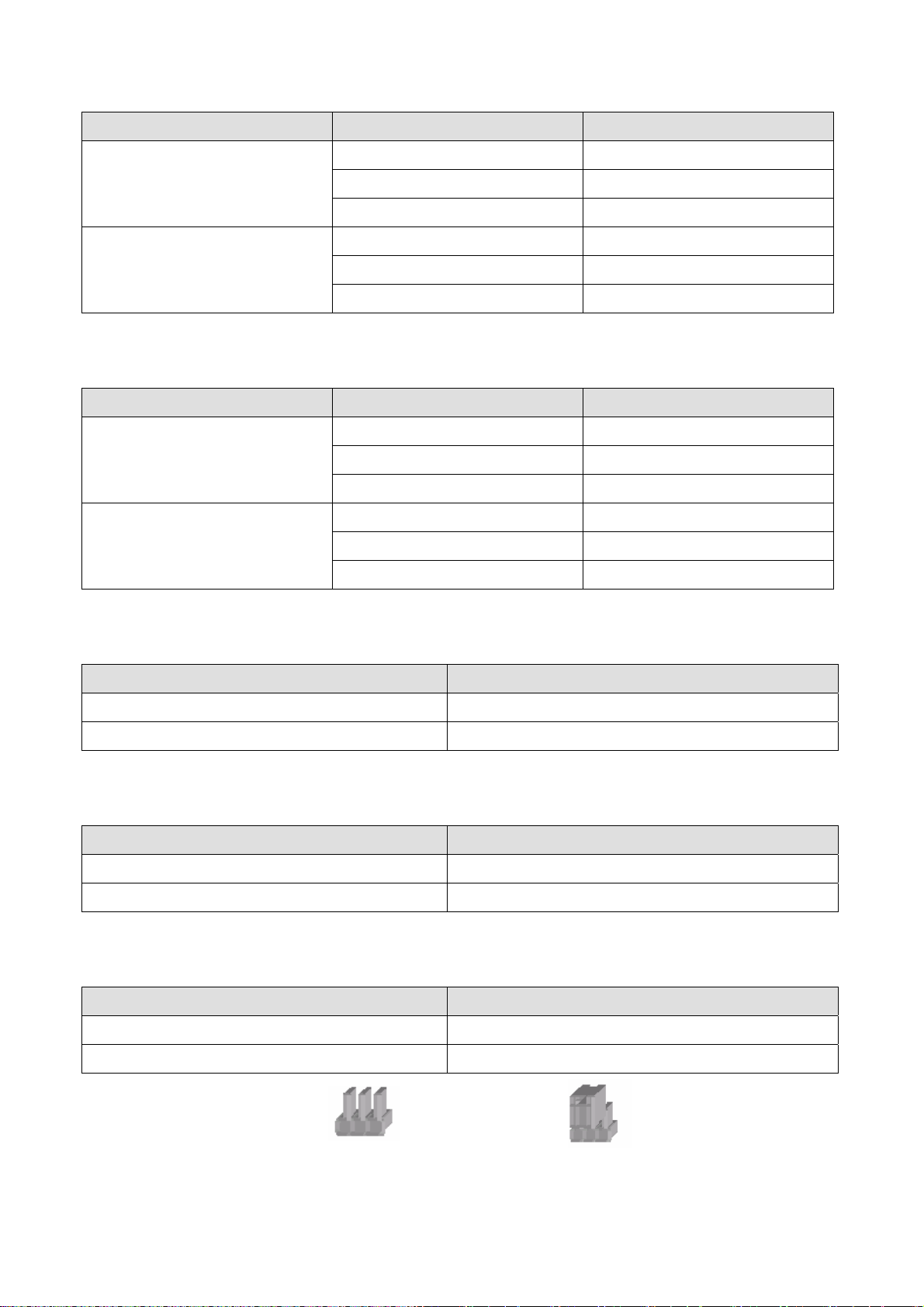
4.1.1 COM 1 Power Selection * Default Setting
Pin Function JP1 (SHORT)
*DCD# 1-2
1
9
VCC 3-4
+12V 5-6
*RI# 7-8
VCC 9-10
+12V 11-12
4.1.2 COM 2 Power Selection
Pin Function JP2 (SHORT)
*DCD# 1-2
1
9
VCC 3-4
+12V 5-6
*RI# 7-8
VCC 9-10
+12V 11-12
4.1.3 Power Mode Selection
Function JP3
*ATX Power OPEN
AT Power SHORT
4.1.4 CMOS Operation modes
Function JP6
*CMOS Normal OPEN
CMOS Reset SHORT
4.1.5 Compact Flash Master/Slave Setting
Function JP7
Note:
*Master OPEN
Slave SHORT
OPEN
/ 37
13
SHORT
Page 14
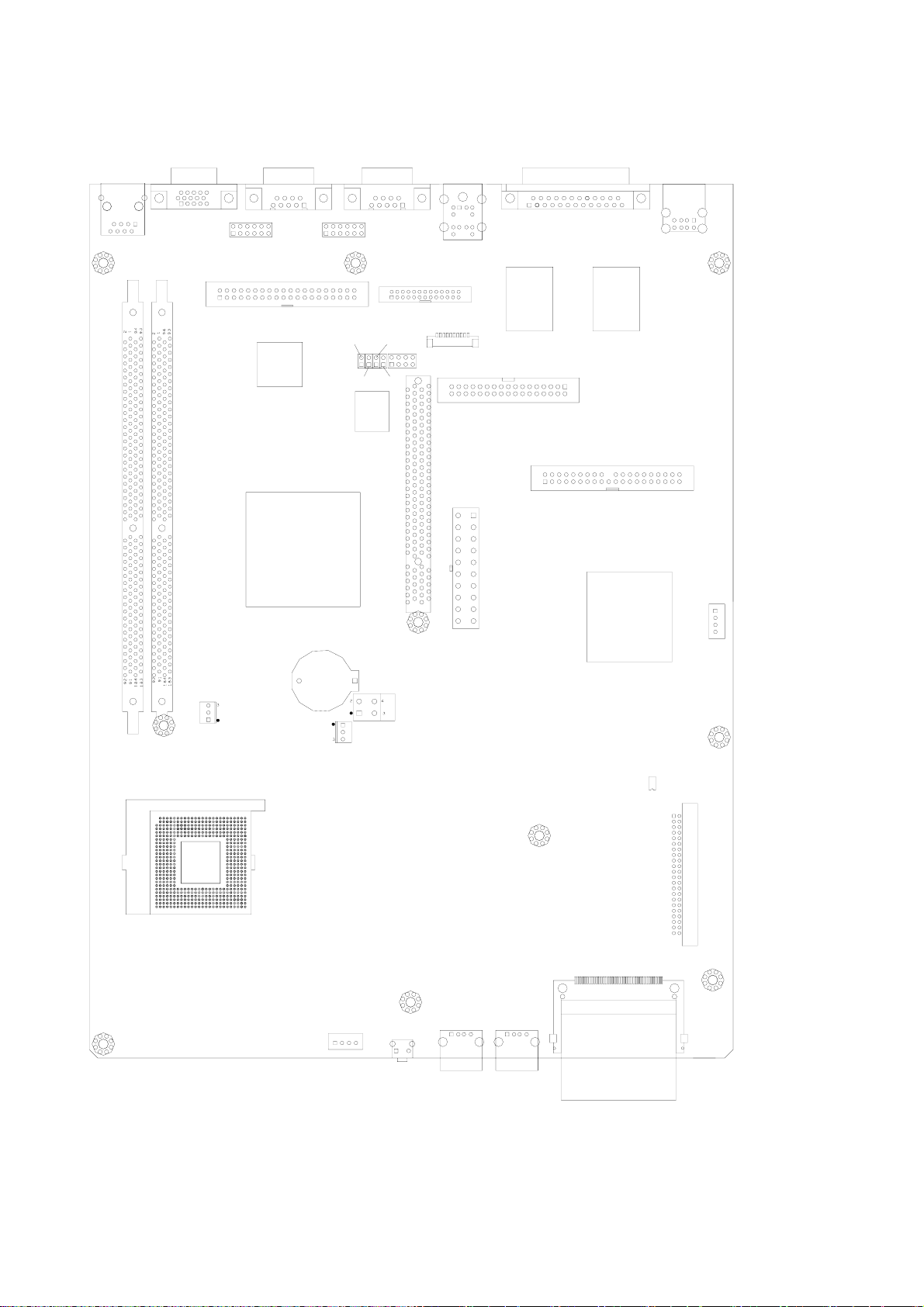
4.2 B79 M/B
RJ45-1
DIMM1
DIMM2
VGA1
COM1
JP1
DATA1
U11
U18
COM2
JP2
JP7
JP3
JP5
JP4
JP6
U14
CN4
PS1
CN1
CN2
FDD1
PWR1
PRN1
USB1
U7
U8
IDE2
CN5
U19
CPU1
FAN-SYS
BAT1
FAN-CPU
CN9
PWR2
U24
IDE3
CN6
SW1
USB3USB2
/ 37
14
Page 15
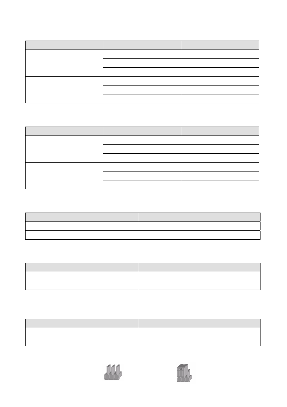
4.2.1 COM 1 Power Selection * Default Setting
Pin Function JP1(SHORT)
*DCD# 1-2
1
9
VCC 3-4
+12V 5-6
*RI# 7-8
VCC 9-10
+12V 11-12
4.2.2 COM 2 Power Selection
Pin Function JP2(SHORT)
*DCD# 1-2
1
VCC 3-4
+12V 5-6
9
4.2.3 Power Mode Selection
Function JP3
*ATX Power OPEN
AT Power SHORT
4.2.4 CMOS Operation mode
Function JP6
*CMOS Normal OPEN
CMOS Reset SHORT
*RI# 7-8
VCC 9-10
+12V 11-12
4.2.5 Compact Flash Master/Slave Setting
Function JP7
*Master OPEN
Slave SHORT
Note:
OPEN
/ 37
15
SHORT
Page 16
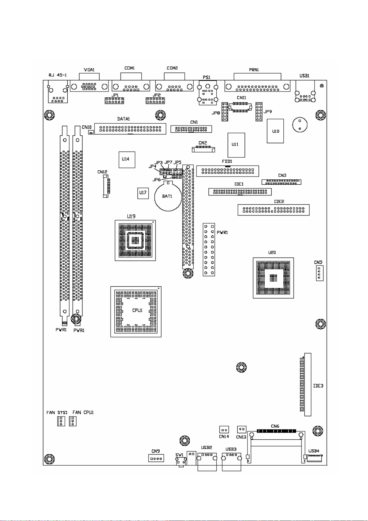
4.3 B49 M/B
/ 37
16
Page 17
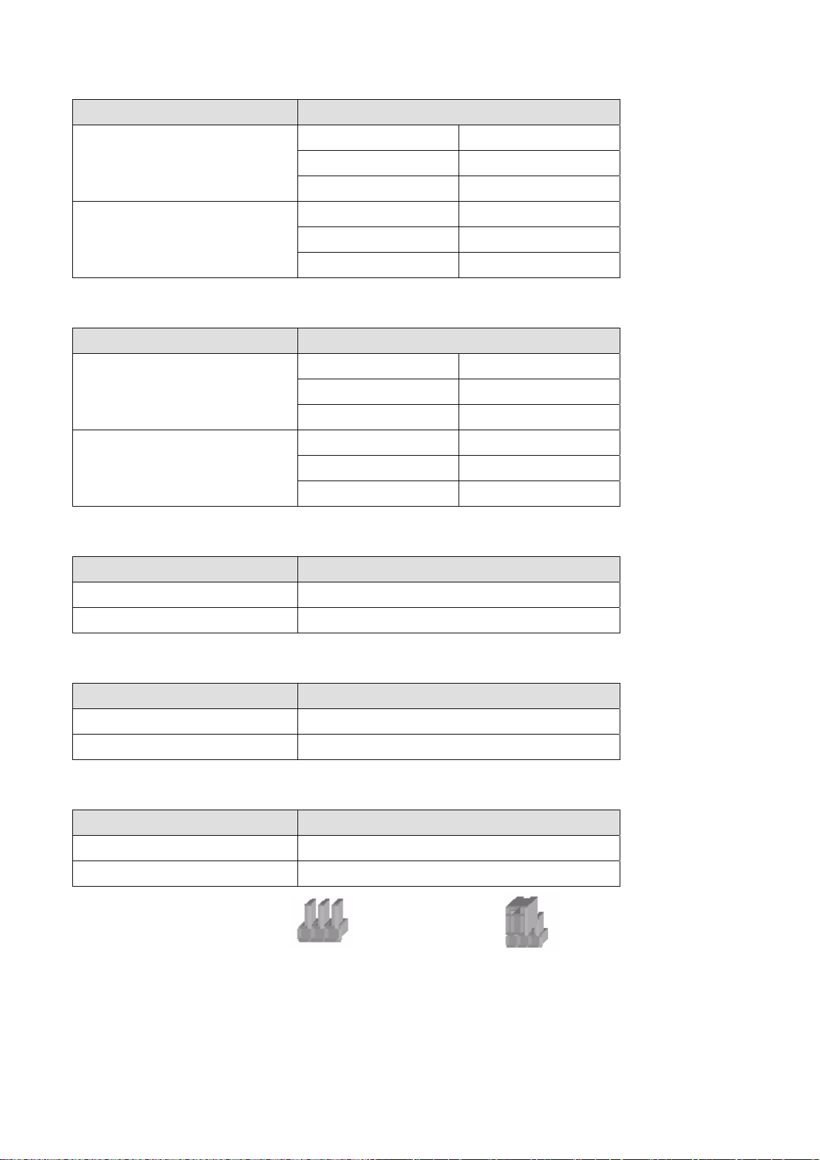
4.3.1 COM1 Power Select * Default Setting
Pin JP1(SHORT)
*DCD# 1-2
1
9
+5V 3-4
+12V 5-6
*RI# 7-8
+5V 9-10
+12V 11-12
4.3.2 COM2 Power Select
Pin JP2 (SHORT)
*DCD# 1-2
1
9
+5V 3-4
+12V 5-6
*RI# 7-8
+5V 9-10
+12V 11-12
4.3.3 Power Mode Setting
Function JP3 (SHORT)
* A TX Power 1-2
AT Power 2-3
4.3.4 CMOS Clear Selection
Function JP6 (SHORT)
* Normal
Clear 2-3
1-2
4.3.5 Compact Flash Master/Slave Setting
Function JP7
SHORT
SHORT
Note:
* Master
Slave OPEN
OPEN
/ 37
17
Page 18
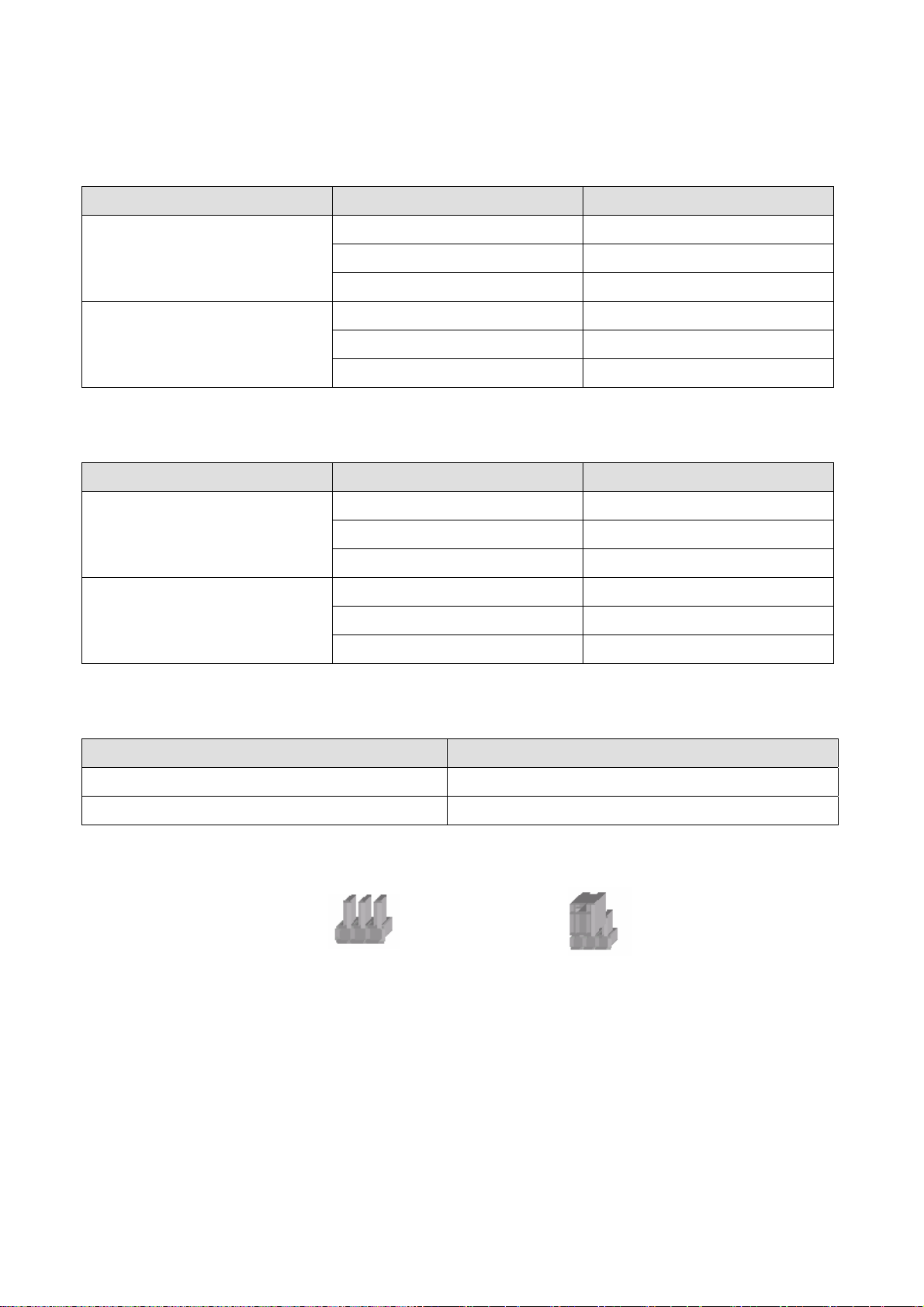
4.4 POS I/O Board Jumper Setting
4.4.1 COM 3 Power Selection * Default Setting
Pin Function JP4(SHORT)
*DCD# 1-2
1
9
4.4.2 COM 4 Power Selection
Pin Function JP3(SHORT)
1
VCC 3-4
+12V 5-6
*RI# 7-8
VCC 9-10
+12V 11-12
*DCD# 1-2
VCC 3-4
9
4.4.3 Cash Drawer Power Selection
Function JP2(SHORT)
24V 1-2
*12V 2-3
Note:
OPEN
+12V 5-6
*RI# 7-8
VCC 9-10
+12V 11-12
SHORT
/ 37
18
Page 19
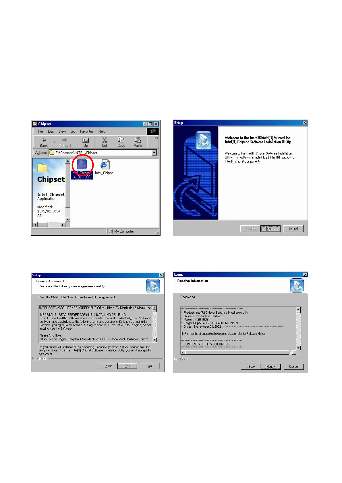
5. Driver Installation
5.1 B69 M/B
The following procedures are for Windows 98SE, other platforms are similar.
5.1.1 Chipset Driver Installation
Driver path: <CD>:\Common\INTEL\Chipset
a. Click "Intel_Chipset_4_20_1006" on the
My Computer window.
c. Click "Next" button on the License
Agreement window.
b. Click "Next" button on the welcome
window.
d. Click "Next" button on the Read me
Information window.
/ 37
19
Page 20
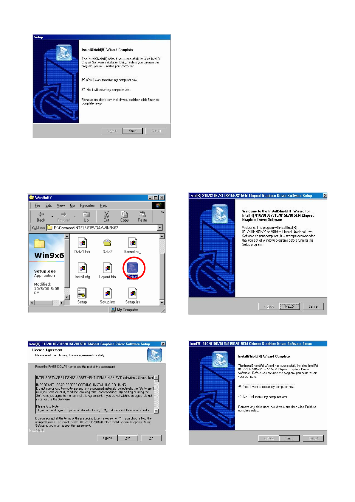
e. Click ”Finish” and restart your system.
5.1.2 VGA Driver Installation
Driver path: <CD>:\Common\INTEL\i815VGA
a. Click "Setup" on the My Computer window. b. Click "Next" button on the welcome window.
c. Click "Next" button on the License
Agreement window.
d. Click ”Finish” and restart your system.
/ 37
20
Page 21
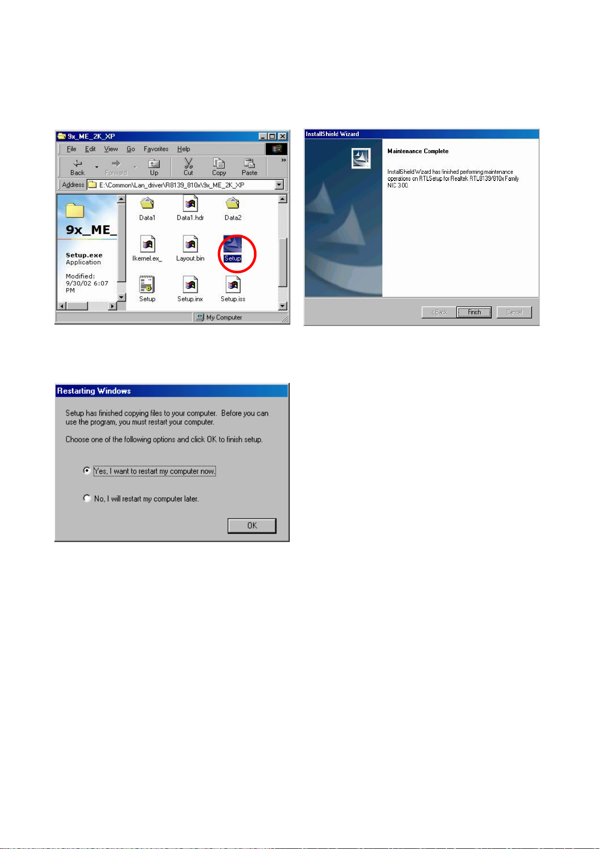
5.1.3 LAN Driver Installation
Driver path: <CD>:\Common\Lan_driver\ R8139_810x\9x_ME_2K_XP
a. Click ”Setup” on the My computer
windows.
c. Click ”OK” to restart the system.
b. Click "Finish" button on the Maintenance
complete window.
/ 37
21
Page 22
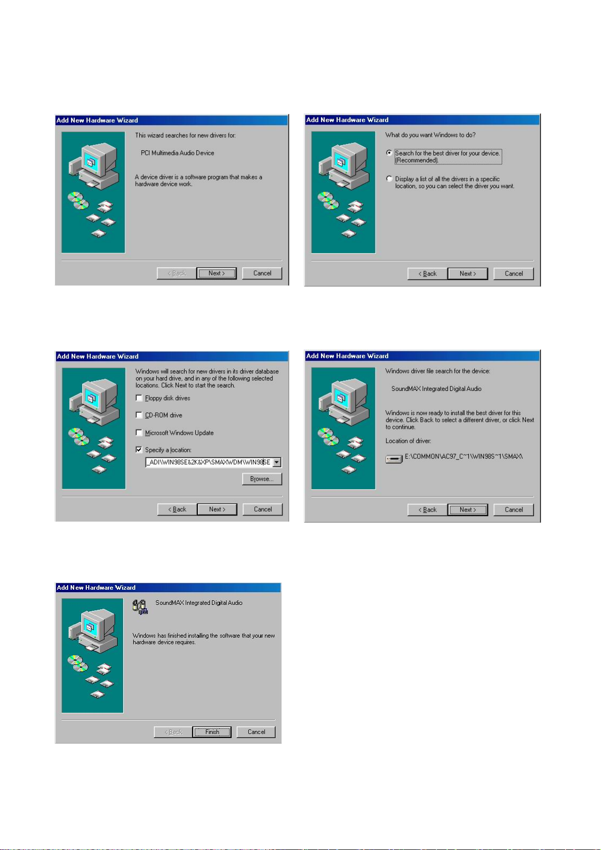
5.1.4 Audio Driver Installation
Driver path: <CD>:\Common\Ac97_codec\ADI\AD1881A
a. Click ” Next” button on the Add New
Hardware Wizard window.
b. Click ” Next” on the Add New Hardware
Wizard window.
c. Browse the driver path and Click “Next”
button.
d. Click ” Next” button on the Add New
Hardware Wizard window.
e. Click ” Finish” button on the Add New
Hardware Wizard window.
/ 37
22
Page 23
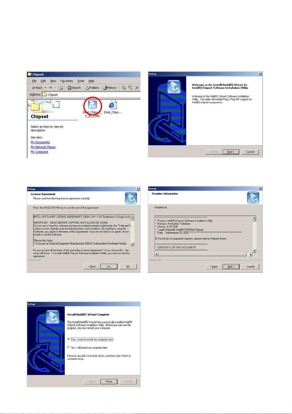
5.2 B79 M/B
The following procedures are for Windows 2000, other platforms are similar.
5.2.1 Chipset Driver Installation
Driver path: <CD>:\Common\INTEL\Chipset
a. Click ” Intel_Chipset_4_20_1006” on the
My computer windows.
c. Click "Yes" button on the License
Agreement window.
b. Click “Next” button on the Welcome
window.
d. Click "Next" button on the ReadME
window.
e. Click ”Finish” to restart the system.
/ 37
23
Page 24
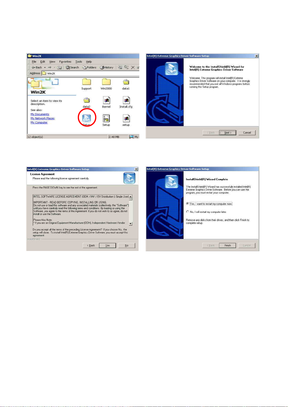
5.2.2 VGA Driver Installation
Driver path: <CD>:\Common\INTEL\i845VGA
a. Click ” Setup” on the My computer
windows.
b. Click “Next” button on the Welcome
window.
c. Click "Yes" button on the License
d. Click ”Finish” to restart the system.
Agreement window.
/ 37
24
Page 25
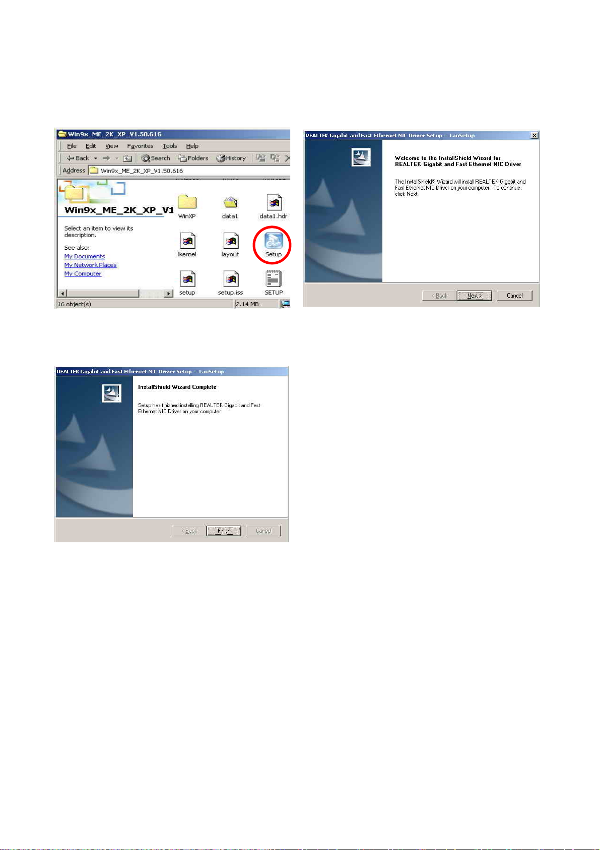
5.2.3 LAN Driver Installation
Driver path: <CD>:\Common\LAN_driver\R8139_810x
a. Click “Setup” on the My computer
window.
b. Click “Next” button on the Welcome
window.
c. Click “Finish” on the LanSetup window.
/ 37
25
Page 26
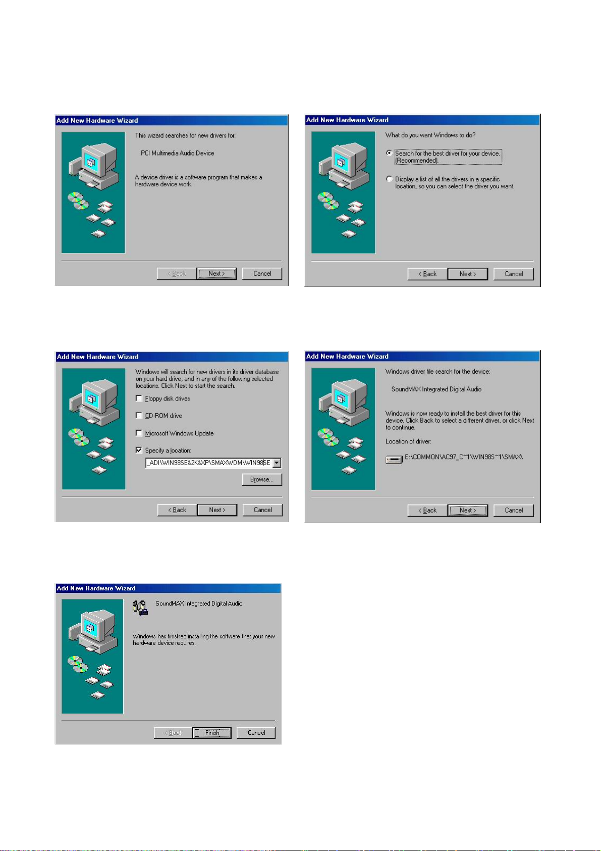
5.2.4 Audio Driver Installation
Driver path: <CD>:\Common\Ac97_codec\ADI\AD1881A
a. Click ” Next” button on the Add New
Hardware Wizard window.
b. Click ” Next” on the Add New Hardware
Wizard window.
c. Browse the driver path and Click “Next”
button.
d. Click ” Next” button on the Add New
Hardware Wizard window.
e. Click ” Finish” button on the Add New
Hardware Wizard window.
/ 37
26
Page 27
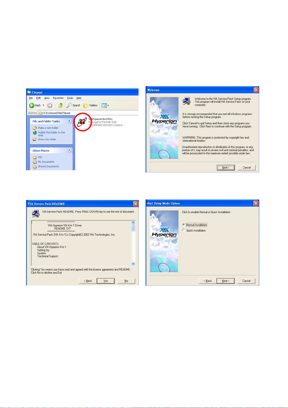
5.3 B49 M/B
The following procedures are for Windows XP, other platforms are similar.
5.3.1 Chipset Driver Installation
Driver path: <CD>:\Common\VIA\Chipset
a. Click “VIAHyperion4in1453v” on the My
computer window .
c. Click “Yes” button on the ReadME
window.
b. Click “Next” button on the Welcome
window.
d. Click “Next” button on the 4in1 Setup
Mode Option window.
/ 37
27
Page 28
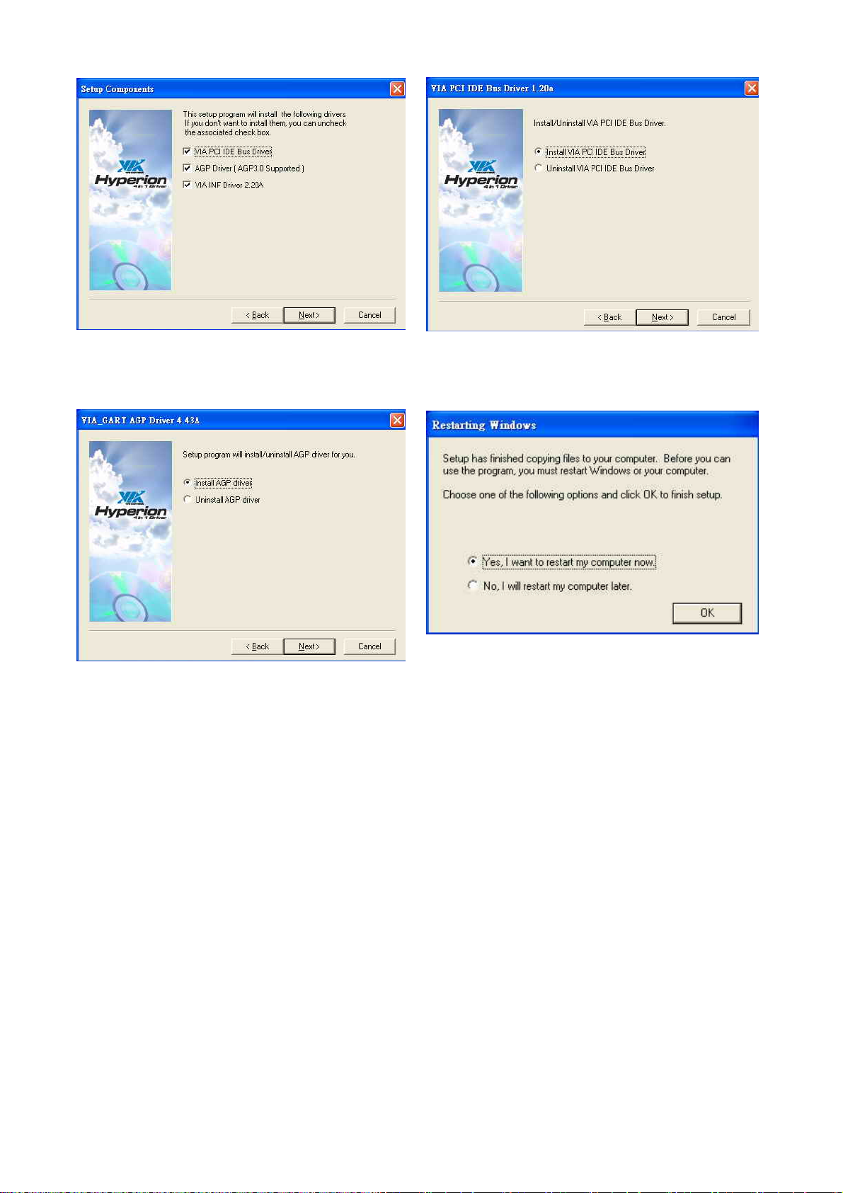
e. Click “Next” button on the Setup
Component window.
f. Click “Next” button on the VIA PCI IDE
Bus Driver window.
g. Click “Next” button on the VIA_GART
h. Click “OK” button to restart the system.
AGP Driver window.
/ 37
28
Page 29
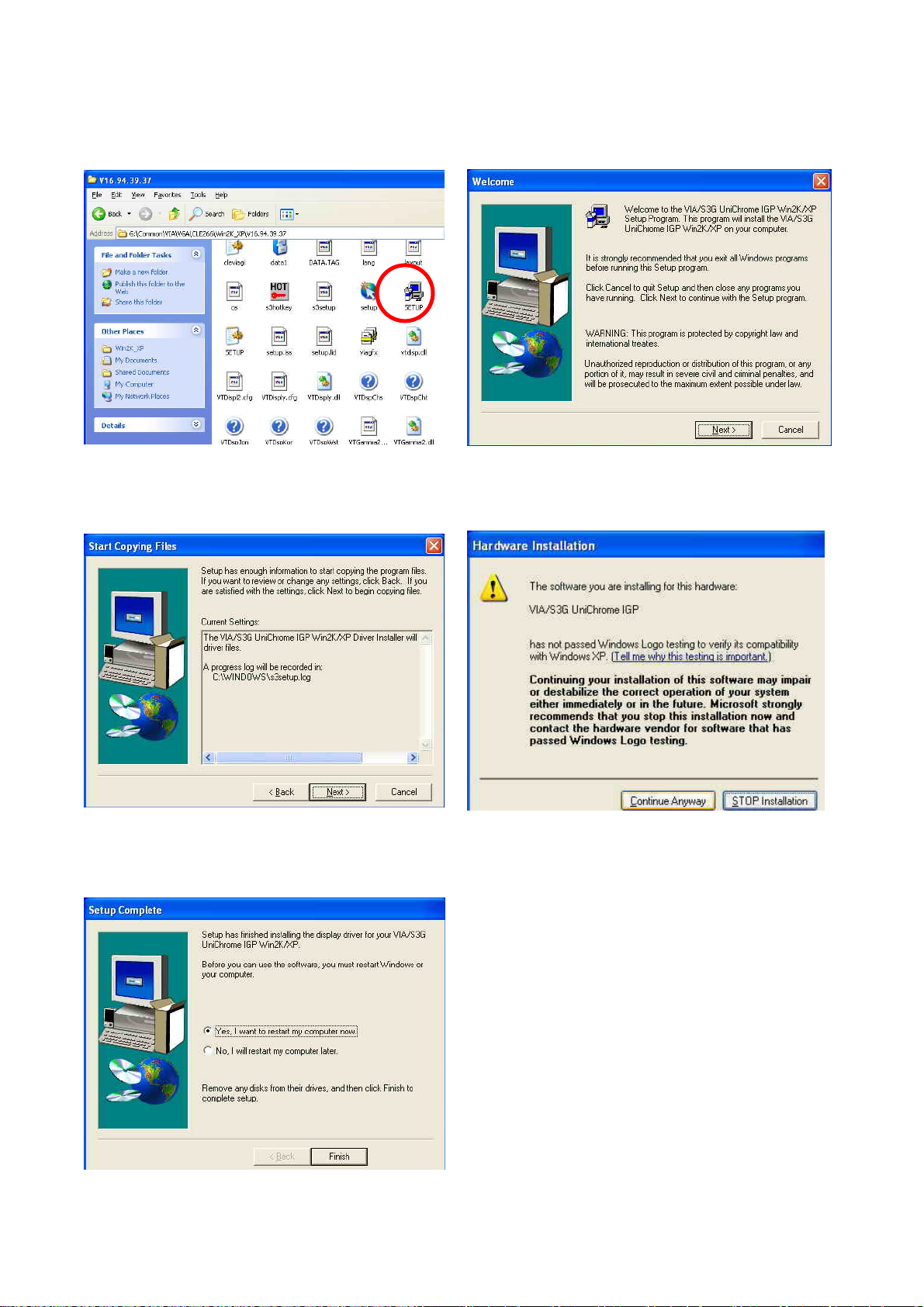
5.3.2 VGA Driver installation
Driver path: <CD>:\Common\VIA\VGA\CLE266
a. Click “Setup” on the My computer
window.
b. Click “Next” button on the Welcome
window.
c. Click “Next” button on the Start Copying
Files window.
d. Click “Continue Anyway” button on the
Hardware Installation window.
e. Click “Finish” button to restart the
system.
/ 37
29
Page 30
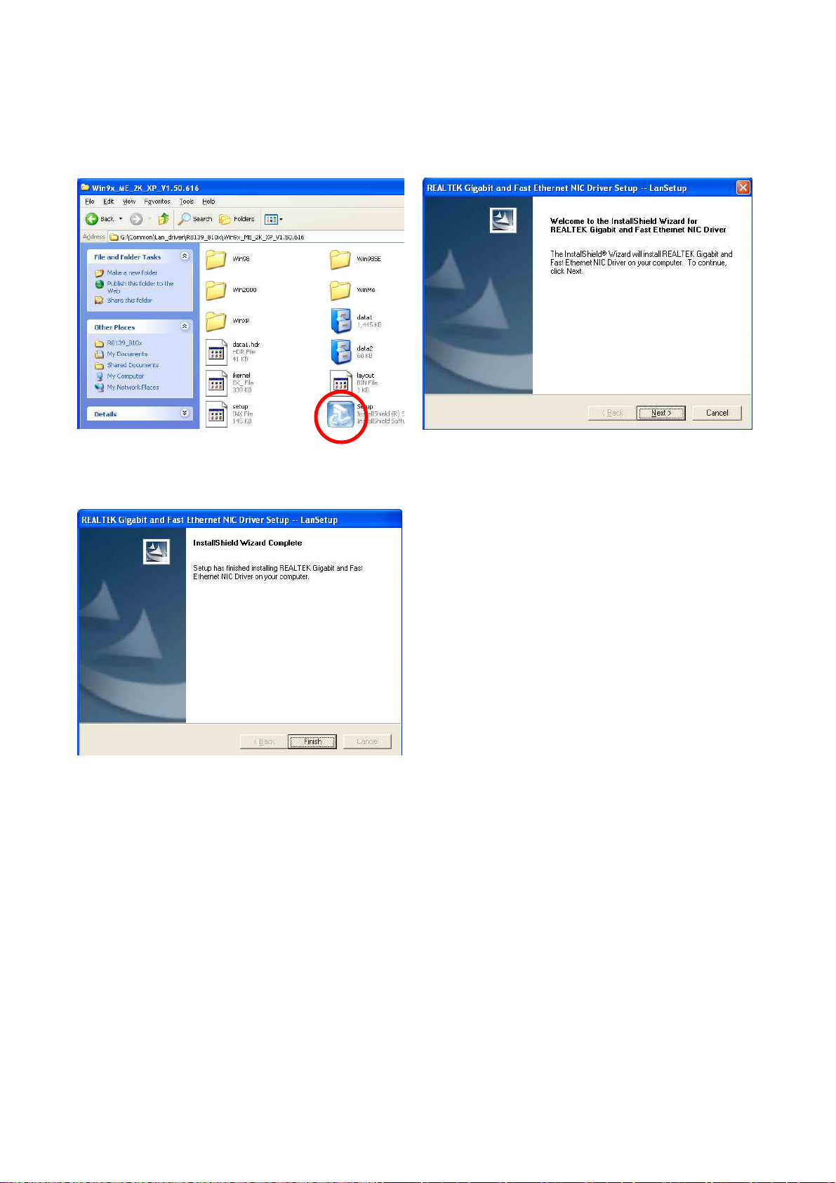
5.3.3 LAN Driver Installation
Driver path: <CD>:\Common\LAN_driver\R8139_810x
a. Click “Setup” on the My computer
window.
b. Click “Next” button on the Welcome
window.
c. Click “Finish” button on the LanSetup
window.
/ 37
30
Page 31
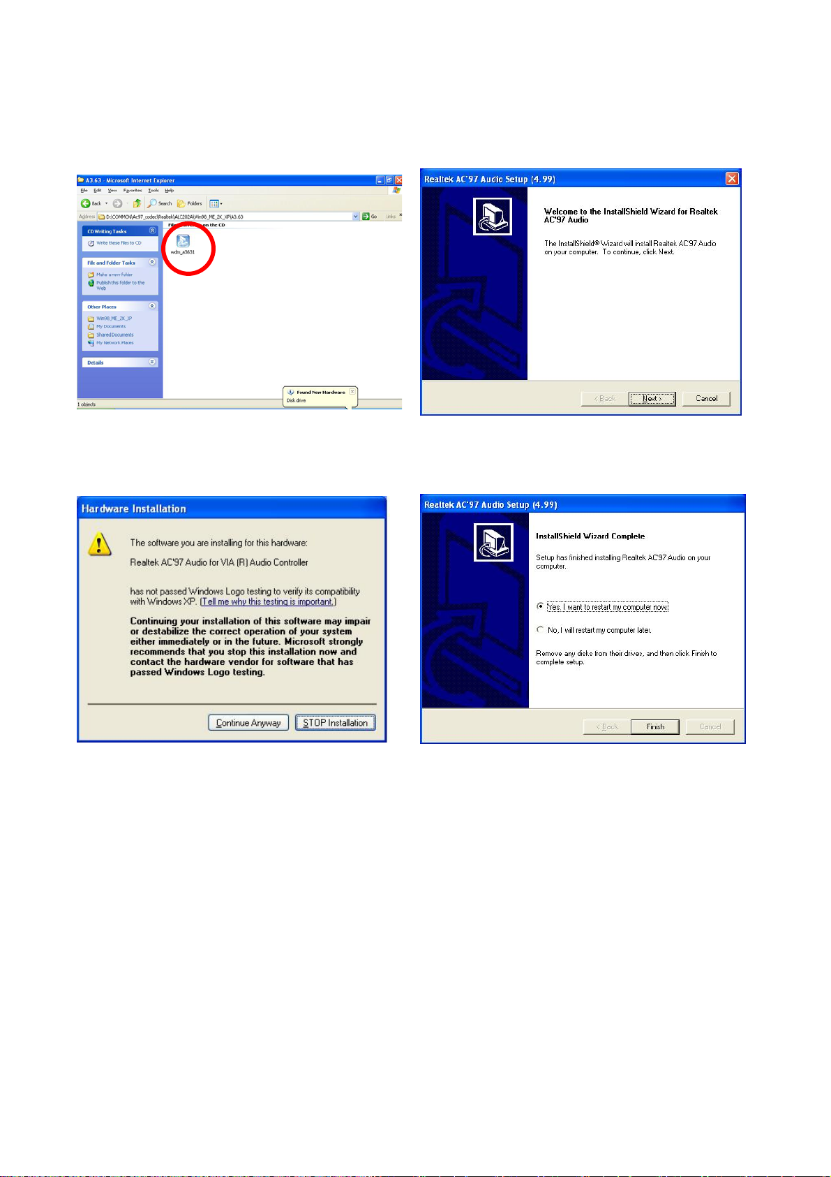
5.3.4 Audio Driver Installation
Driver path: <CD>:\Common\Ac97_codec\Realtek\ALC202A)
a. Click “wdm_a3631” on the My computer
window.
b. Click “Next” button on the Welcome
window.
c. Click “Continue Anyway” button on the
d. Click ”Finish” button to restart system.
Hardware Installation window.
/ 37
31
Page 32
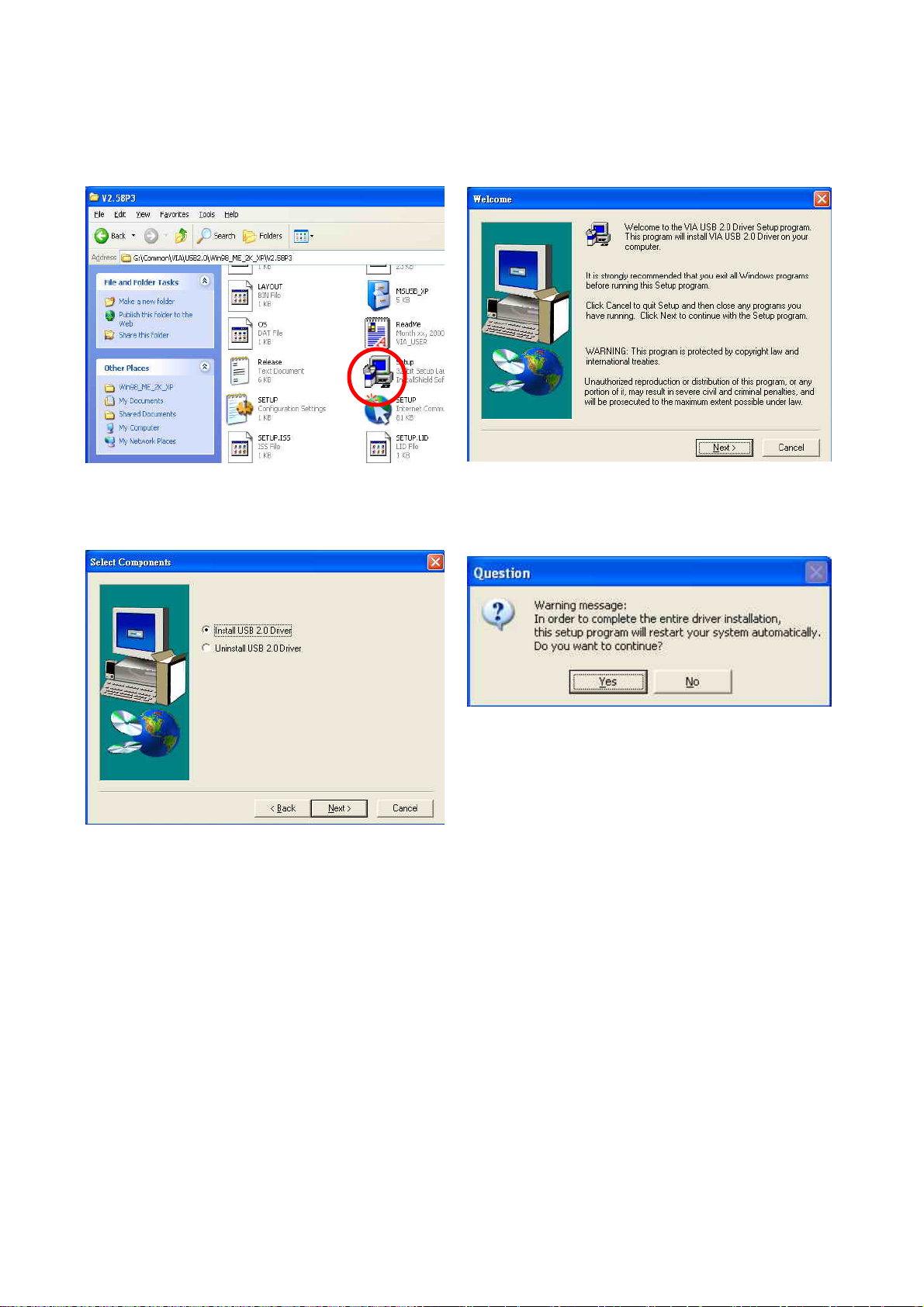
5.3.5 USB 2.0 Driver Installation
Driver path: <CD>:\Common\VIA\USB2.0
a. Click “Setup” on the My computer
window.
c. Click “Next” button on the Setup
Component window.
b. Click “Next” button on the Welcome
window.
d. Click ”Yes” button to restart system.
/ 37
32
Page 33
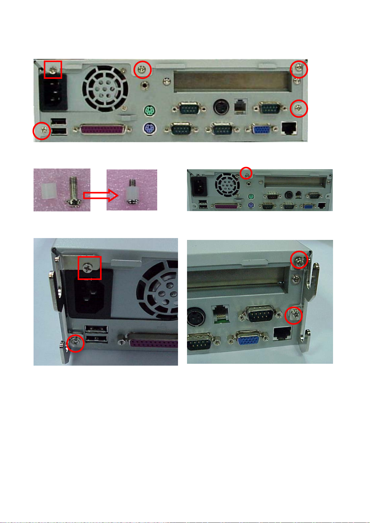
6.Installation the Cable Cover
a. Loosen the five screws (4mmx4, 6mmx1 ( 32UCN )).
b. Insert the screw (8mm) into the plastics. c. Lock the screw.
d. Lock the brackets with screws. (6mmx3, 6mmx1 (32UCN)).
/ 37
33
Page 34
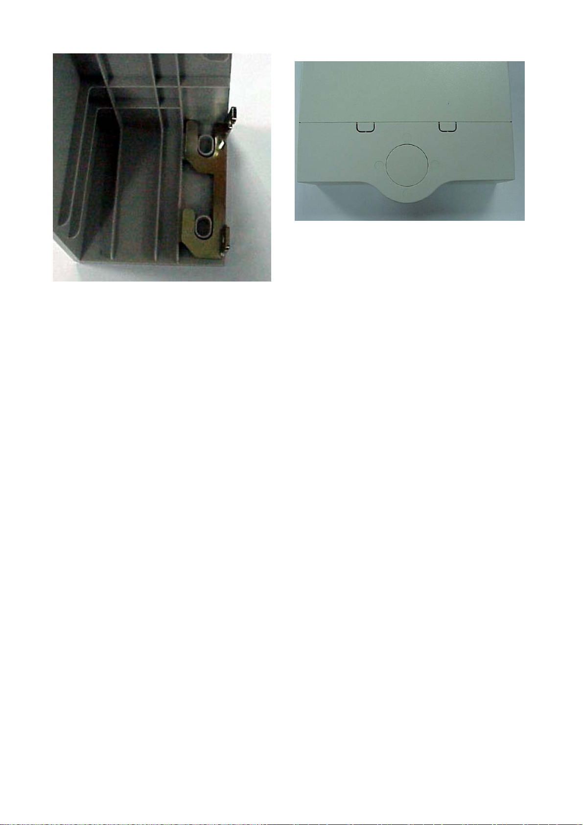
e. Installation the cable cover. f. Finished.
/ 37
34
Page 35
7. Installation Cash Drawer
You can install a cash drawer through the Cash Drawer port.
7.1 Cash Drawer Pin Assignment
Pin Signal
1 GND
2 DOUT bit0
3 DIN bit0
4 12V/24V
5 DOUT bit1
6 GND
Data out address (200h)
Data in address (201h)
7.2 Cash Drawer Controller register
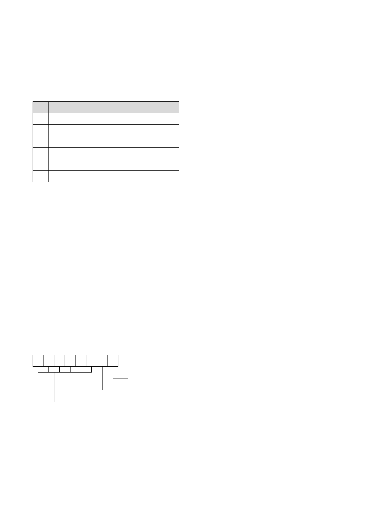
The Cash Drawer Controller use two I/O addresses to control Cash Drawer –Cash
Drawer Control Register and Cash Drawer Status Register.
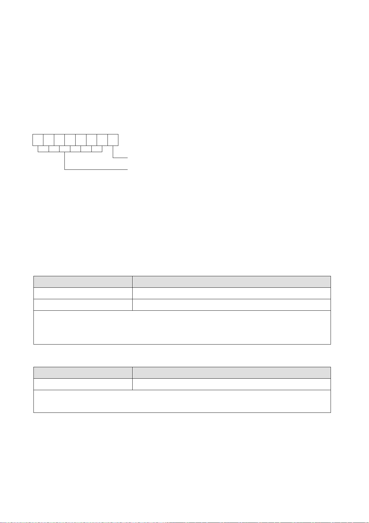
7.2.1 Cash Drawer Control Register
Register Location: 200h
Attribute: Write only
Size: 8bit
7 6 5 4 3 2 1 0
X X X X X X
Cash Drawer “DOUT bit0” pin output control
Cash Drawer “DOUT bit1” pin output control
Reserved
Bit 7-2: Reserved
Bit 1: Cash Drawer “DOUT bit1” pin output control.
= 1: Opening the Cash Drawer
= 0: Allow close the Cash Drawer
Bit 0: Cash Drawer “DOUT bit0” pin output control.
= 1: Opening the Cash Drawer
= 0: Allow close the Cash Drawer
/ 37
35
Page 36
Note: Please follow the Cash Drawer control signal design to control the Cash Drawer.
Suggest control the bit1/0 at the same time.
7.2.2 Cash Drawer Status Register
Register Location: 201h
Attribute: Read only
Size: 8bit
7 6 5 4 3 2 1 0
X X X X X X X
Bit 7-1: Reserved
Bit 0: Cash Drawer “DIN bit0” pin input status.
Cash Drawer “DIN bit0” pin output control
Reserved
= 1: the Cash Drawer opened or not exist.
= 0: the Cash Drawer closed.
7.3 Cash Drawer control command example
Use Debug.EXE program under DOS or Windows98
Command Cash Drawer
O 200 01 Opening
O 200 00 Allow to close
¾ Set the I/O address 200h bit0 =1 for opening Cash Drawer by “DOUT bit0” pin
control.
¾ Set the I/O address 200h bit0 = 0 for allow close Cash Drawer.
Command Cash Drawer
I 201 Check status
¾ The I/O address 201h bit0 =1 mean the Cash Drawer is opened or not exist.
¾ The I/O address 201h bit0 =0 mean the Cash Drawer is closed.
/ 37
36
Page 37
8. Notices
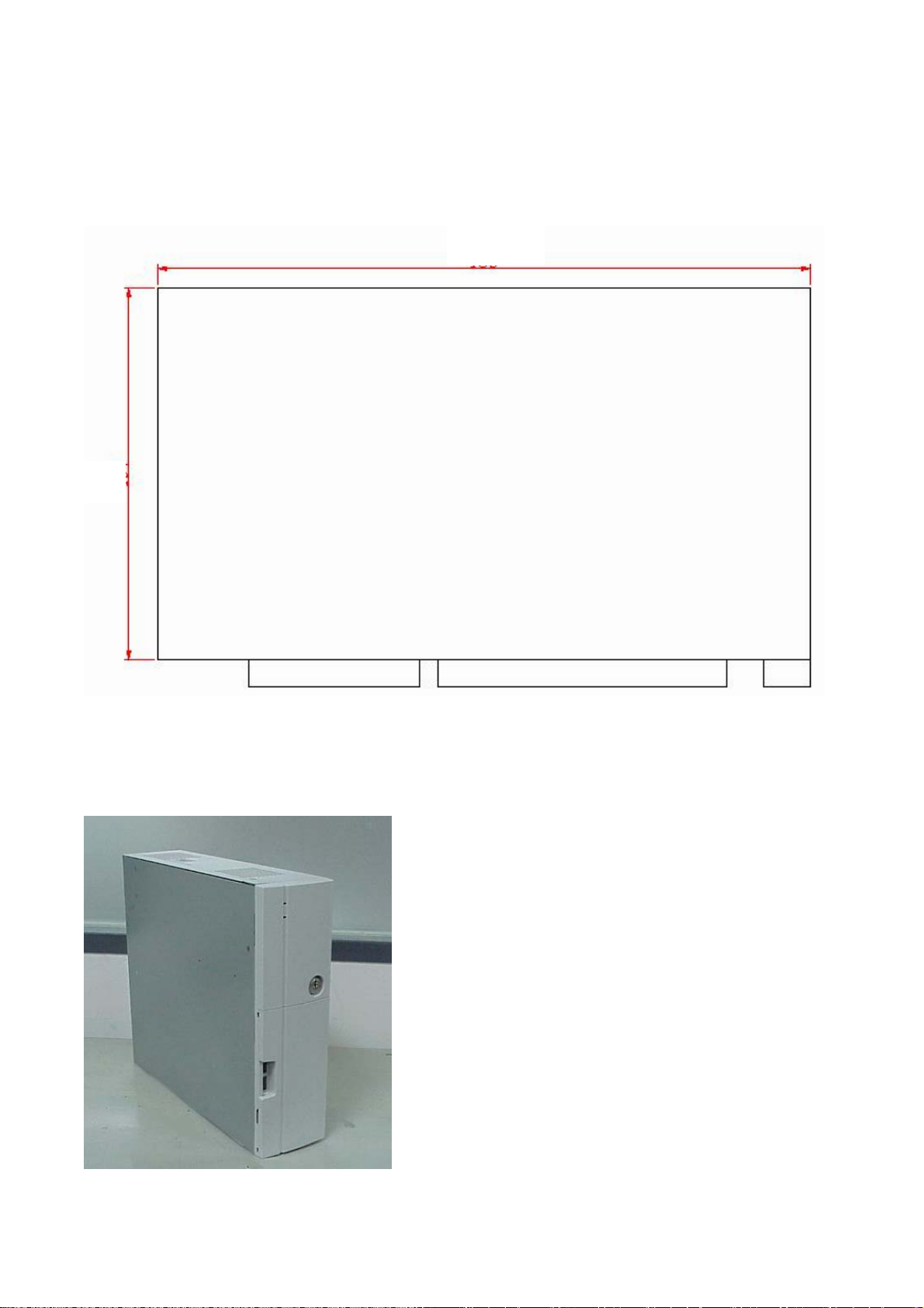
8.1 Maximum dimension of Interface card
(Maximum dimension of Interface card: 183 mm x 104 mm)
183mm
104 mm
8.2 Vertical position of POS 4000
POS4000 vertical position must keep vent hole on top side, storage device on desk side.
/ 37
37
 Loading...