

Venom Air Corps Night Ranger 3dxl Pilot's Handbook Manual

World Class Product s World Class Value World Class Product s World Class Value World Class Product s World Class Value World Class Product s
I. INTRODUCTION
Venom Air Corps™ Night Ranger 3DXL™ is a high performance Ready-to-Fly Collective Pitch (CP)
Aerobatic Electric Helicopter for indoor flying and outdoors on calm days. At about 610 grams, the
VNR 3DXL™ will fly for 5-8 minutes on the 11.1v 10c 3s 1500mah LiPO battery, depending on the
type of flight. Although the VNR 3DXL™ is not difcult to operate, it does take more skill and practice
to master than a xed pitch helicopter. We recommend that you read these instructions thoroughly and
carefully rst. If you have any questions, please feel free to call our customer service department or
contact your local hobby shop or local flying club. All are excellent resources for information and
are more than willing to help new hobbyists.
WARNING!
SPECIFICATIONS:
Helicopter # .....................................................VENF-6230
Helicopter Name .............................................VNR 3DXL™
Main Rotor Diameter .......................................625mm
Fuselage Length .............................................595mm
Weight .............................................................610g
Battery ............................................................. 11.1v 10c 3s 1500mah LiPO
Radio Controller .............................................. 7 Channel FM
Servo ............................................................... 4 Micro Servos
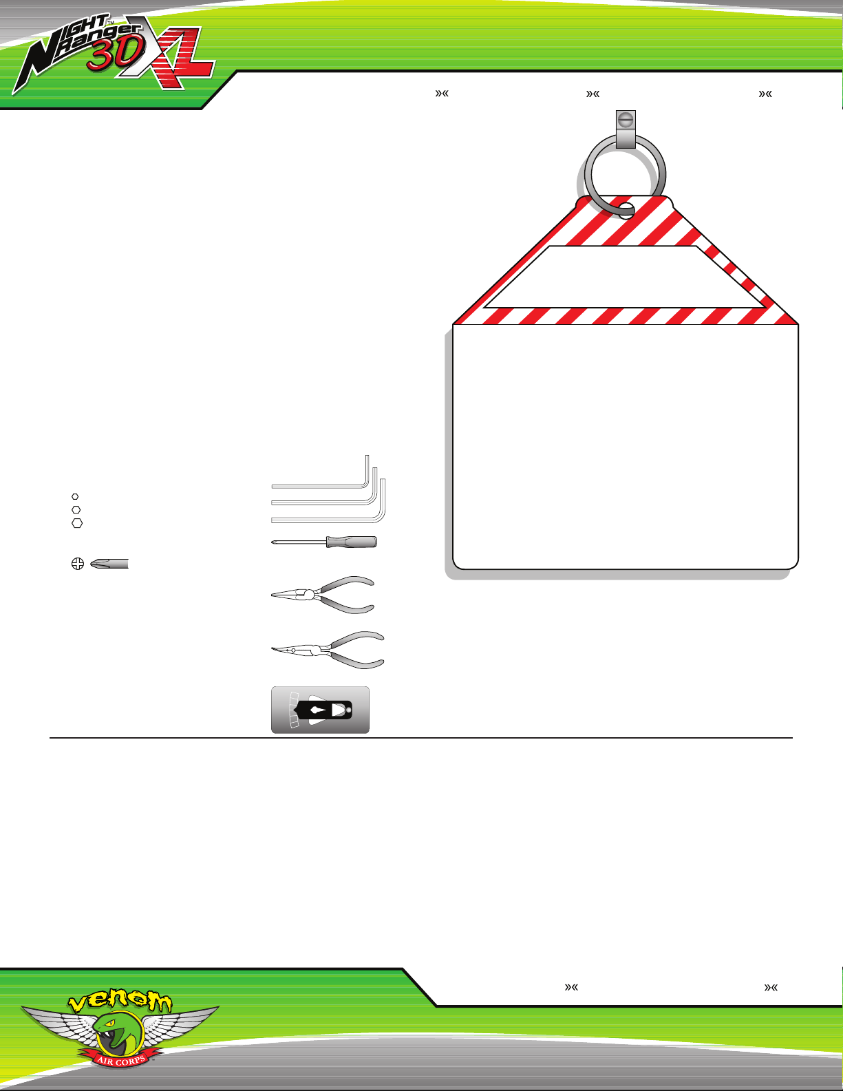
TOOLS NECESSARY:
- 1.5, 2, 2.5mm Allen Wrenches
1.5mm
2.0mm
2.5mm
- #0 3/32” Phillips Screwdriver
No.0
- Needle Nose Pliers
- Ball Pushrod Pliers (optional)
o
+15
o
- Micro Pitch Gauge (optional)
+10
o
+5
o
0
o
-5
o
-10
o
-15
READ BEFORE FLIGHT
The VNR 3DXL™ is not a toy. It is a precision machine requiring proper assembly
and setup to avoid accidents and it is the responsibility of the owner to operate this
product in a safe manner as it can cause serious personal injury and damage to
property due to carelessness or misuse.
When charging the battery pack, do not overcharge! If batteries get hot during
charging, discontinue charging immediately and disconnect the battery from the
charger. Never leave battery unattended while charging. If you are unsure of how to
charge this battery, please contact Venom Air Corps™ or seek the advice of your
local hobby shop. Never let children charge batteries without adult supervision.
To avoid an out of control helicopter always turn the radio on rst then connect the
battery to the helicopter. When turning off the helicopter, always disconnect the
battery rst, then turn off the radio. If the orders are reversed the helicopter may
become uncontrollable and cause serious damage.
If you are in doubt of your ability, we strongly recommend that you seek assistance
from experienced radio controlled helicopter pilots or join your local helicopter
flying club to gain the required knowledge and skill. As the manufacturer and
distributor, we assume no liability for the use of this product.
Children under the age of fourteen (14) are strictly prohibited from playing with this
electric helicopter.
GUARANTEE
We guarantee that the VNR 3DXL™ to be free of manufacturing
faults and material defects. This product has been checked and
adjusted individually before leaving the manufacturer. Please contact
your local hobby shop for replacement parts and technical support or
contact Venom Air Corps™ Customer Service at 800.705.0620 or
customerservice@venom-aircorps.com. To help identify broken or
damaged parts we have included a detailed parts list and assembly
diagram at the end of this instruction manual.
:
II. INSTALLATION
CHARGING THE BATTERY:
ALWAYS REMOVE THE BATTERY BEFORE CHARGING! Plug the
power supply into a wall outlet, then attach the LiPO Balance Charger
(VEN-0653). Both LEDs will illuminate. The Left LED will be GREEN and
the Right LED will be RED. Plug the battery into the correct charging port
on the charger and the Left LED will change to RED and start flashing
rapidly. When the battery is charged, the Left LED will turn GREEN. It
will take approximately 2 hours to fully charge. The charge time will vary
based on starting battery level. If the battery gets warm or hot during
charging, disconnect the battery and set it on a non-flammable surface
and allow it to cool down and look for any swelling or pufng in the pack.
See LiPO handling instructions on page 19 for information.
INSTALLING THE BATTERY:
Slide the battery into the battery tray with the battery lead end facing
the front right of the helicopter. Slide the battery in so that the battery
front edge is flush with the bottom battery tray front edge. To secure
the battery tightly with the included Hook & Loop strap, wrap the strap
around the battery and the tray.
INSTALLING THE CANOPY:
Slide the canopy onto the helicopter. Spread the side of the canopy apart
Venom Air Corps www.venom-aircorps.com Venom Air Corps www.venom-aircorps.com Venom Air Corps
2
so that the bottom front rubber grommets can slip over the bottom front
canopy mounts. Then slip the top rear set of rubber grommets onto the
top rear canopy mounts.
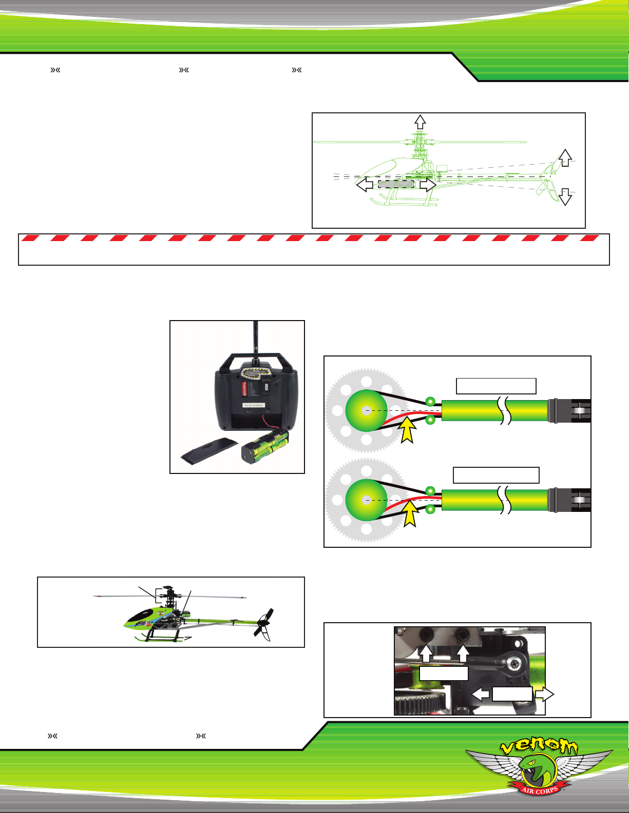
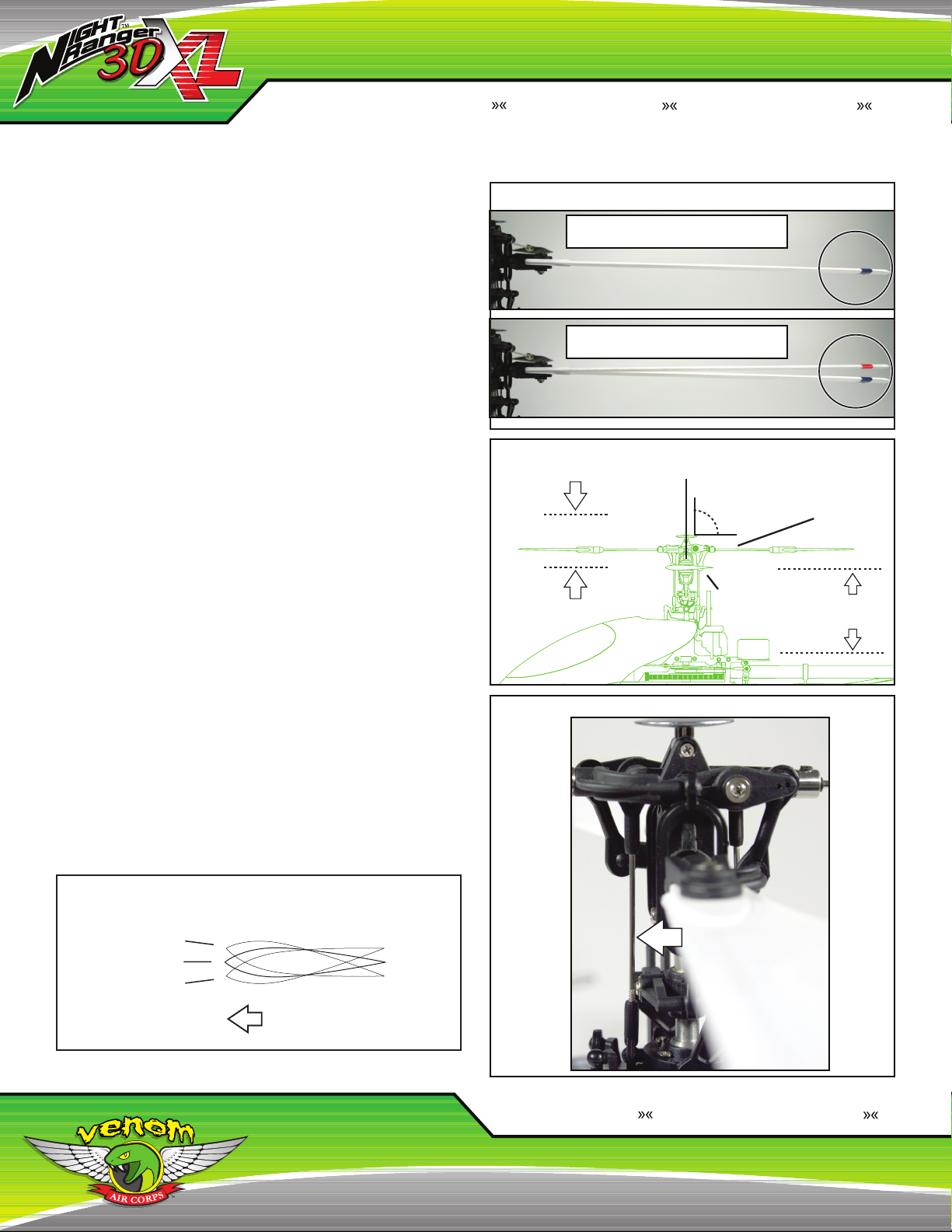
Check the Center of Gravity (CG)
It is recommended that once the battery is fully charged and installed,
that the CG is checked. To adjust the CG, position the flybar at a 90o
angle to the tail boom. Pick up the VNR 3DXL™ by the flybar and
position the battery so that the tail boom is parallel to the floor (Fig. A)
III. MAIDEN FLIGHT CHECKLIST
Fig. A
The boom should be level with the ground when the VNR 3DXL™ is lifted by the flybar. If
it is not, move the battery forward or backwards to balance. Always check the CG with the
battery and canopy installed.
Note: Lift by Flybar
Nose Heavy
Level
Tail Heavy
PRE-FLIGHT:
IT IS IMPORTANT TO PERFORM THIS PRE-FLIGHT SAFETY CHECK
BEFORE EVERY FLIGHT.
1. Assembling the Radio
Install eight (8) AA batteries into
the removable battery tray from
the back of the radio. Facing the
radio, twist the antenna into the
socket on the top of the radio
clockwise until it is tight. A loose
antenna could cause intermittent
control, running the risk of losing
control of the helicopter. (Fig. B)
2. Check for Loose Items
It is important to check the
helicopter for loose screws and
nuts before flight, in case they
have loosened in shipping. For
specic areas to check see (Fig. C).
- Tighten any loose screws. Only apply thread locking compound to
screws that have metal to metal contact, if needed.
- Ensure all components such as the Gyro and Receiver are
secured to the airfame.
- Check the Motor Mount and Servo Mounting screws.
- Check for any Servo Wires which may be touching the Spur Gear.
- Check the Head Assembly down to the Swash Plate.
- Check Tail, Tail Boom Mount/Belt Tension.
Fig. C
Head Assembly
& Swash Plate
Fig. B
Tail Boom Mount/Guide Pulley Set
Landing Skids
4. Adjusting the Tail Rotor Belt Tension
Inspect the belt tension to make sure it is properly set. If it is too loose,
the belt can slip causing unpredictable tail control and damage to the
belt. If the belt is too tight, it will rob the helicopter of power and can
also have adverse effects on tail control. Check the belt tension by
pressing on the belt right between where it enters the boom and the
main mast. You should be able to press the belt to roughly half the
distance to the other side of the belt. See (Fig. D)
Fig. D
Correct Tension
Large Pulley
Belt
Small Pulley
Tail Boom
Small Pulley
Incorrect Tension
Large Pulley
Belt
Small Pulley
Tail Boom
Small Pulley
If the tension is not correct, adjust it by sliding the boom in or out of
its housing. First, loosen the two screws that hold the tail boom in
place. These screws are located on the top right side of the front edge
of the boom. Next, loosen the horizontal n screws so the boom can
be pulled out straight. Once they are loose, pull the boom out if the
tension is too loose . Push the boom in if there the tension is too tight
(Fig. E).
Fig. E
3. Check for Cracked or Damaged Parts
Any part that is cracked or damaged on the helicopter can cause
unpredictable flight performance. Specic areas to check (Fig. C):
- Landing Skids
- Tail Boom Mount
- Blade Grips
Loosen
Adjust
3
World Class Product s World Class Value World Class Product s World Class Value World Class Product s World Class Value World Class Product s
III. MAIDEN FLIGHT CHECKLIST (CONT)
BASIC RADIO INTRODUCTION:
IT IS IMPORTANT TO HAVE A BASIC UNDERSTANDING OF THE
LAYOUT OF THE RADIO BEFORE FLYING IN NORMAL FLIGHT
MODE. PLEASE NOTE: RADIO MODE I IS FOR PILOTS IN EUROPE
& AUSTRALIA. RADIO MODE II IS FOR PILOTS IN NORTH AMERICA.
BOTH RADIO MODES WILL BE EXPLAINED ON PAGE 7.
The VNR 3DXL™ radio offers advanced functionality and control. When
you turn on the radio, it will go through an initialization process
that takes 3-4 seconds. During this initialization the display lights
will ash multiple colors. It will then go to a solid purple on the logo
and red, yellow, and green on the battery indicator. It is important
to note that if the Flight Mode switch is ipped to 3D Flight Mode,
the radio will initialize but the logo will not light up and the power
meter will ash to let you know that the 3D Flight Mode needs to be
set on Normal Flight Mode. Once the switch is set, it is not required
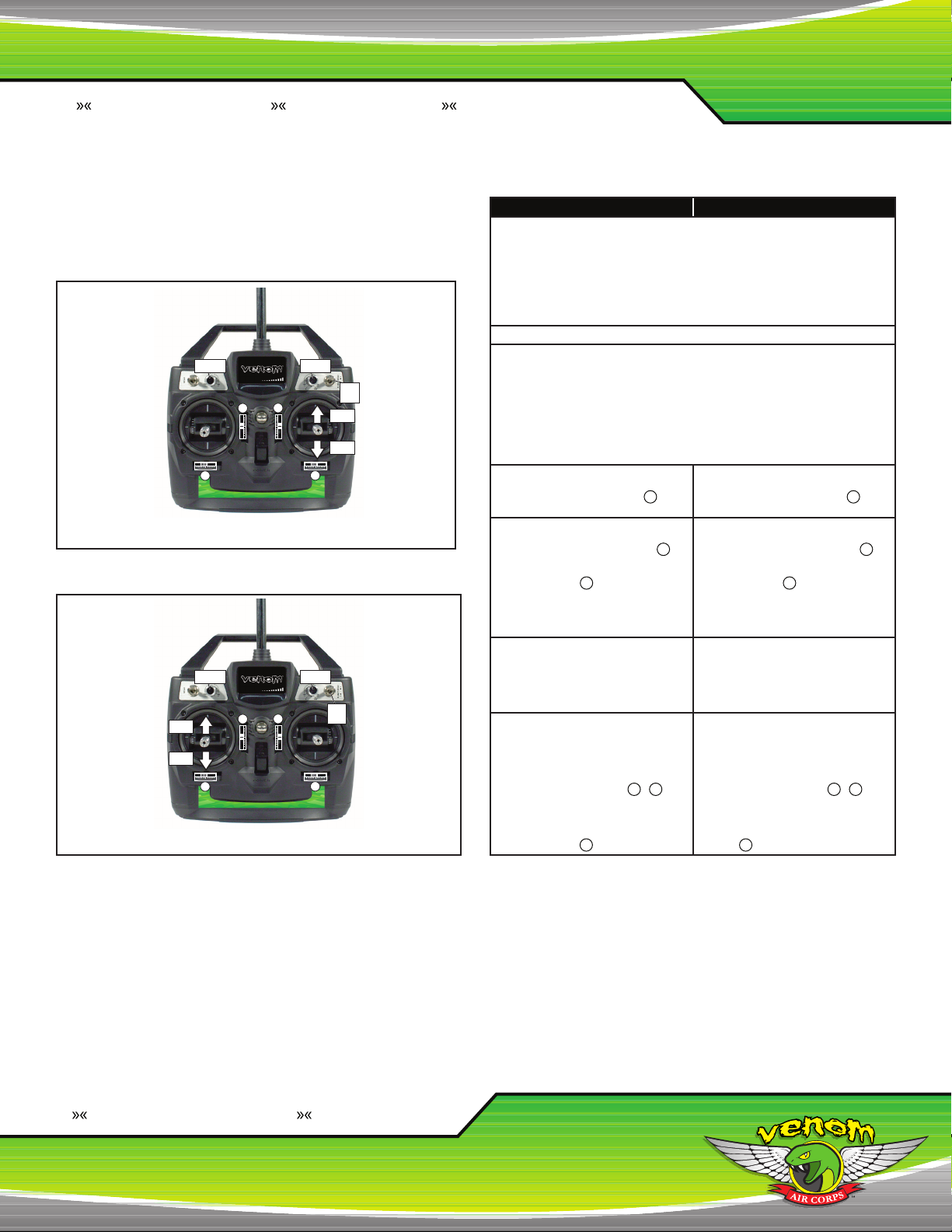
to cycle the power in order to continue to y. In MODE II - North
America, the left control stick controls Throttle and the Tail Rotor (Fig. F).
The right control stick controls the Elevator and Aileron. There are four
trims that control the Throttle/Pitch, Tail Rotor, Elevator Cyclic and Aileron
Cyclic. Along the top of the radio are two switches and two dials. The
Gear switch is an auxiliary switch and is only functional if an additional
servo is plugged into channel port #5 on the receiver. This is perfect if
you are using a scale body that happens to have retractable landing gear.
The Flight Mode switch is used to switch between Normal Flight Mode
(indicated by “N”) and 3D Flight Mode (indicated by “1”). The dials labeled
V1 and V2 are used for several different adjustments that can be made to
the helicopter’s programming including the Pitch and Throttle Curves
(explained in the Flight Envelope Section), Servo Exponential, and even
Remote Adjustment of the Gyro. The back of the radio has a series of
DIP switches that are used for servo reversing, several pre-programmed
settings, and in the case of DIP switches #10, #11, and #12, they are
used to operate the programmable settings.
NOTE: The radio conguration is for MODE II. For MODE
I ight control instruction, please refer to page 7.
Fig. F
Gear Switch/
Auxiliary *
Adjustment
Throttle
100%
50%
0%
Pitch
Full
Throttle
Left Tail
Rotor
Throttle
Off
Right Tail
Rotor
Aileron
Left
(DIP switches are located
on the underside of the radio.)
* Gear Switch is not operational will only be functional if an
additional servo is plugged into Channel #5 on the receiver.
Elevator
Elevator
Down
Up
Adjustment
Right
Aileron
Throttle
FLIGHT MODE
N1
Normal Flight Mode
3D Flight Mode
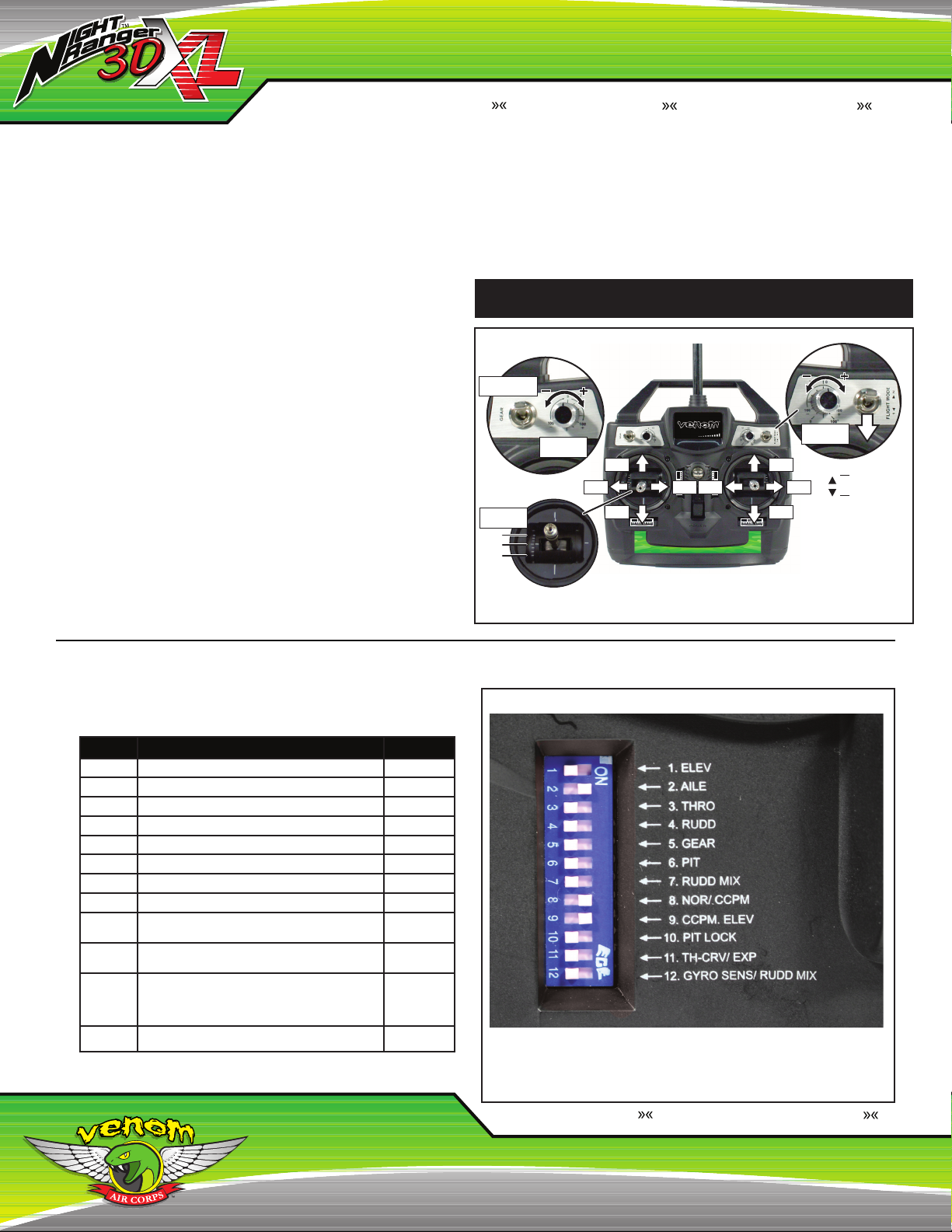
RADIO DIP SWITCHES:
Below is a list of DIP switches with their respective descriptions and
preferred settings as from the factory (Fig. G):
DIP # Description Setting
1 Elevator Servo Reversing (Front Swashplate Servo) OFF
2 Aileron Servo Reversing (Back Right Swashplate Servo) ON
3 Throttle Function Reversing OFF
4 Tail Rotor Servo Reversing (Servo In Front of the Motor) OFF
5 Retract Servo Reversing (Operational, Not Used) OFF
6 Pitch Servo Reversing (Back Left Swashplate Servo) OFF
7 Throttle To Tail Rotor Mixing OFF
8 Mechanical/CCPM Mixing Option ON
9 CCPM Elevator Reversing Function: Reverses the
whole elevator function, not just the single servo.
10 Pitch Lock Function: Turning this on allows changing the
pitch range and pitch curve in normal flight mode.
11 Throttle Curve/Servo Exponential: Allows the pilot to
change head speed by changing the throttle curve, as
well as dialing in exponential to the aileron and elevator
cyclic.
12 Remote Gyro Gain/Throttle to Tail Rotor Mix Adjustment OFF
ON
OFF
OFF
Fig. G
Factory Settings
When you are ready to fly, verify that the DIP switches are in the factory
set positions shown here. Flying the VNR 3DXL™ with any other
conguration will result in unexpected flying and possible personal injury.
Venom Air Corps www.venom-aircorps.com Venom Air Corps www.venom-aircorps.com Venom Air Corps
4
TURNING ON THE HELICOPTER:
CHECK CONTROL FUNCTIONS:
1. Turn on the radio rst; make sure the throttle stick is in the throttle off
position and the throttle trim in the center position.
2. Make certain the Flight Mode switch is in the Normal Flight Mode
position.
3. Place the helicopter on a flat surface. Plug the battery into the ESC.
When you rst plug in the battery, the LED on the gyro will flash red
rapidly, and then after 5-8 seconds, it will go to a solid red. During
this time it is important that the helicopter is not moved as the gyro is
initializing.
4. Make sure all of the trims are centered.
5. Make sure that the swashplate is level to the ground. If not, see the
Normal Flight Mode Head Adjustment section below. You will use the
trim sliders to ne tune the helicopter once you have completed a test
flight.
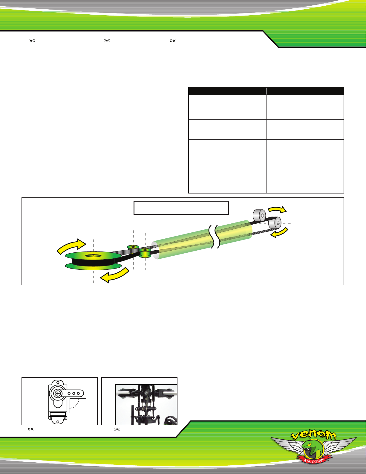
Fig. H
Correct Belt Orientation
Large Pulley
Small Pulleys
Tail Boom
Belt
MODE I - EUROPE & AUSTRALIA MODE II - NORTH AMERICA
Move the RIGHT control sitck to the right and
the swashplate will tilt to the right. Move it to
the left and the swashplate will tilt to the left
(observe from behind the helicopter). (Roll
Control)
Pull the LEFT control stick back towards
you and the swashplate will tilt back. Push it
forward and the swashplate will tilt forward.
(Elevator Control)
Move the LEFT stick to the right and the
Trailing Edge of the tail rotor blades will go to
the right. Move it to the left and the Trailing
Edge of the tail rotor blades will go to the left.
Spin the head clockwise (viewing from
overhead) and the Leading Edge of the tail
blades should rotate up towards the blades
(counter-clockwise when viewed from the
right side of the helicopter). If the tail blades
are not rotating in this direction, the belt has
been twisted the wrong way (Fig. H).
Belt Guide
Move the RIGHT control sitck to the right and
the swashplate will tilt to the right. Move it to
the left and the swashplate will tilt to the left
(observe from behind the helicopter). (Roll
Control)
Pull the RIGHT control stick back towards
you and the swashplate will tilt back. Push it
forward and the swashplate will tilt forward.
(Elevator Control)
Move the LEFT stick to the right and the
Trailing Edge of the tail rotor blades will go to
the right. Move it to the left and the Trailing
Edge of the tail rotor blades will go to the left.
Spin the head clockwise (viewing from
overhead) and the Leading Edge of the tail
blades should rotate up towards the blades
(counter-clockwise when viewed from the
right side of the helicopter). If the tail blades
are not rotating in this direction, the belt has
been twisted the wrong way (Fig. H).
Belt Guide
IV. NORMAL FLIGHT MODE HEAD ADJUSTMENTS
It is important to make sure that the blade pitch is set right in Normal
Flight Mode to achieve high performance in 3D Flight Mode.
1. When making the head adjustments, make sure to disconnect the Main
Motor as a safety precaution.
2. The throttle stick needs to be in the throttle off position.
3. Locate all three pushrods that run from the swashplate to the servo
arms and disconnect them from the swashplate.
4. Turn on the radio and center all the trims. Connect the battery on the
helicopter.
5. Check all three servo arms to see if they are roughly 90o to the servo
Fig. I Fig. J
90º
case by looking directly at each screw head on (Fig. I). If not, loosen
the retaining screw on the servo arm and remove the arm from the
servo case to reveal the splines on the output shaft. These splines are
the little notches that engage into the servo arm. Rotate the servo arm
one spline at a time. If you cannot get the arm to be exactly 90o, set
it to as close to 90o. (NOTE: If you have to adjust the servo arm on
the back servo, you may need to completely remove the front servo to
correctly re-tighten the retaining screw.) Repeat these steps and check
the other two servos. Then re-tighten the retaining screw.
6. With the three pushrods still disconnected from the swashplate,
move the whole swashplate so that it is level to the ground and that
the washout arms are parallel to each other and to the ground when
viewing it from both the sides and front (see Fig. J). Next adjust the
pushrods so that they match up to the pivot balls on the leveled
swashplate. Be careful to not move the servo arms when adjusting the
pushrods. The pushrod can be adjusted by screwing the plastic
5
World Class Product s World Class Value World Class Product s World Class Value World Class Product s World Class Value World Class Product s
IV. NORMAL FLIGHT MODE HEAD ADJUSTMENTS (CONT)
pushrod in or out on the metal rod. Once adjusted, connect the
pushrods to the swashplate. Make sure to connect to the pivot ball that
is directly above the pushrod. In most cases, one of the three will be
much longer or shorter than the other two, so don’t be alarmed. Check
to see if the swashplate and washout arms are still level. If not, repeat
this step.
7. Make sure that the blade pitch on each blade is at 0o pitch. If they
are not, please read below. The goal is to have the proper amount of
positive pitch in Normal Flight Mode, while maintaining a symmetrical
amount of positive and negative pitch in 3D Flight Mode.
BLADE TRACKING & BLADE PITCH
Blade tracking is a crucial component to having good flight
characteristics. If the blades do not track properly (if they do not follow
the same path when they are spinning) they can create vibrations and
instability (Fig. K). The tracking has been set at the factory but may need
some minor adjustments to optimize it.
Check the Blade Tracking:
1. Apply blade tip decals. Choose two different colors.
2. Disconnect the motor lead.
3. Set the cyclic control trims to center on the radio.
4. Turn on the radio and helicopter.
5. Examine the swashplate. The swashplate must be 90o square to the
Main Shaft when observed from the front and from the side (Fig. L).
6. Viewing the VNR 3DXL™ from the side, rotate the flybar so that it is
parallel to the tail boom and level to the ground. The flybar must also
be 90o square to the Main Shaft when checking the pitch. (Fig. L).
Sight down the length of the blade closest to you.
7. The main rotor blades must be parallel to the flybar and swashplate
(Fig. L).
8. Note the angle (pitch) of the blade. The blade pitch angle must be 0o
as a starting point (Fig. M).
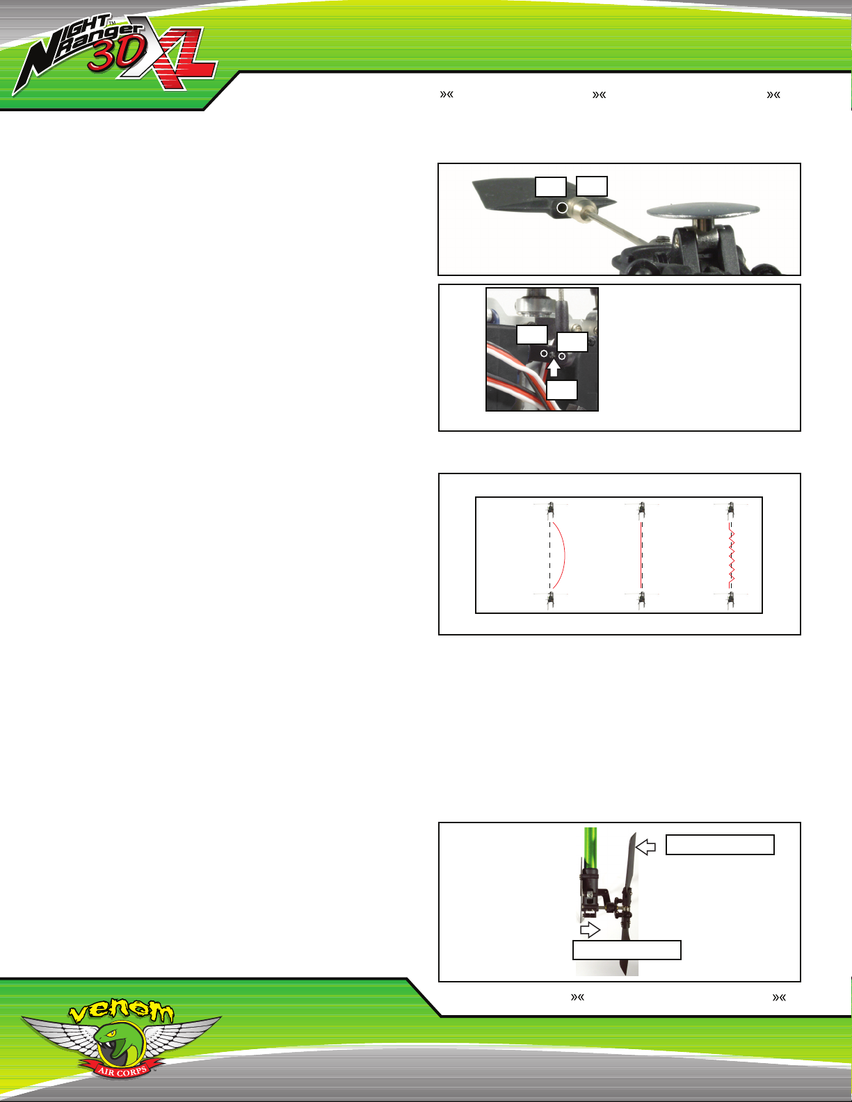
9. To adjust the blade pitch angle (see Fig. N). NOTE: Adjust the left
pushrod in view which corresponds to the blade facing you.
10. Repeat steps 6 - 9 for the other blade.
Fig. K
Correct Tracking
Incorrect Tracking
Fig. L
Main Shaft
90º
Parallel
0º
Main Blade
Fig. N
Flybar
Parallel
Once these steps are completed, you are ready to flight check the
tracking while hovering (hover at waist level). After ne tuning the radio
trims, check the blade tracking and adjust by using the previous steps.
TIP: For more accuracy in tracking the blades, it is recommended to
use a Pitch Gauge.
Fig. M
Positive
Pitch
+10º
0º
-10º
Negative
Pitch
Blade Rotation
Adjusting the Long
Pushrod increases
or decreases pitch.
Turn to the right to
decrease. Turn to
the left to increase.
Venom Air Corps www.venom-aircorps.com Venom Air Corps www.venom-aircorps.com Venom Air Corps
6
RADIO TRIM ADJUSTMENTS
(FINE TUNING):
NOTE: MODE I - EUROPE & AUSTRALIA
Fig. O
Throttle
Adjustment
3D
Mode
4
Throttle
Adjustment
4
Throttle
Throttle
Mode
Switch
Switch
Up
Down
3D
3
3
Fig. P
Pitch
Adjustment
2
1
NOTE: MODE II - NORTH AMERICA
Pitch
Adjustment
Throttle
Up
Throttle
Down
2
1
MODE I - EUROPE & AUSTRALIA MODE II - NORTH AMERICA
ATTENTION: BEFORE CONNECTING THE BATTERY TO THE ESC, YOU MUST CONFIRM
THE FOLLOWING SETTINGS. MAKE SURE THE VNR 3DXL™ IS TURNED OFF DURING
THIS PROCESS!
1. The crystals on the radio and the receiver must match each other.
2. Antenna is screwed in and extended, batteries are fully charged and radio has been turned
on.
3. The throttle stick must be located in the throttle off position, otherwise serious damage to the
VNR 3DXL™ and personal injury may occur.
4. Make sure the Flight Mode switch is in the Normal Flight Mode.
If all of the above settings are confirmed, connect the battery to the ESC.
After the battery is connected, wait for the gyro to initialize (as described on page 5) before
flying. If the LED does not blink after the battery is connected, please check that you have
switched on the radio and that the battery is fully charged.
NOTE: If the throttle stick is not in the throttle off position when the battery is connected, the
gyro will still initialize but the throttle stick will not be active until it is returned to the throttle off
position. If the radio is working properly and the helicopter suddenly seems to shut off, that
condition is the result of a loss of signal or interference. The radio system has a built in fail safe
to prevent a run away helicopter. In the event of signal loss, the receiver is designed to stop its
activity and neutralize the helicopter to minimize damage to it and any property it may come in
contact with.
If the main rotor blades start rotating, and
the right control stick has not been pushed
forward, slowly adjust the radio trim 3 until
they stop rotating.
Make sure the swashplate is horizontal to the
ground. If the swashplate is not horizontal
from front to back, adjust the radio trim 2
until it is level to the ground (Fig. O). If the
swashplate is not horizontal from side to side,
adjust the radio trim 4 until it is level to the
ground (Fig. O). Test the flight controls to
make sure they are operating properly and
the swashplate moves in the direction you
want to fly.
Push the right control stick slightly forward
to start the blade rotation. Keep your fingers,
eyes and other objects clear of the rotating
parts. When the main rotor blades start
rotating, the tail blades should start rotating
simultaneously.
Slowly push the right control stick forward
to increase rotor speed. The VNR 3DXL™
may not take off vertically; it may go forward
or backwards, left or right. Continue to push
the right control stick forward and bring the
helicopter to a hovering height of waist high.
While hovering, use trim sliders 2 & 4 to
fine tune the VNR 3DXL™ while hovering.
You may also find the helicopter’s nose
will swing to the left or right side when you
increase throttle. In this case, you need to
adjust the radio trim 1 .
If the main rotor blades start rotating, and
the left control stick has not been pushed
forward, slowly adjust the radio trim 2 until
they stop rotating.
Make sure the swashplate is horizontal to the
ground. If the swashplate is not horizontal
from front to back, adjust the radio trim 3
until it is level to the ground (Fig. P). If the
swashplate is not horizontal from side to side,
adjust the radio trim 4 until it is level to the
ground (Fig. P). Test the flight controls to
make sure they are operating properly and
the swashplate moves in the direction you
want to fly.
Push the left control stick slightly forward to
start the blade rotation. Keep your fingers,
eyes and other objects clear of the rotating
parts. When the main rotor blades start
rotating, the tail blades should start rotating
simultaneously.
Slowly push the left control stick forward to
increase rotor speed. The VNR 3DXL™ may
not take off vertically; it may go forward or
backwards, left or right. Continue to push
the left control stick forward and bring the
helicopter to a hovering height of waist high.
While hovering use trim sliders 3 & 4 to fine
tune the VNR 3DXL™ while hovering. You
may also find the helicopter’s nose will swing
to the left or right side when you increase
throttle. In this case, you need to adjust the
radio trim 1 .
V. TUNING THE VNR 3DXL™
LESS RESPONSIVE:
- Reducing the throw of the Aileron and Elevator Cyclic will help make
the helicopter less sensitive. To do this move the pivot balls on the
servo arm to the inner most holes.
- With the head speed function selected (DIP switch #11) you can turn
down the head speed, which allows for a longer flight and makes
the helicopter less sensitive to control inputs. Do note that in windy
conditions, it is better to run a little bit higher head speed.
MORE RESPONSIVE:
- Increase the head speed, this will give you a faster response time,
but less flight time. Refer to the Pitch Range & Curve Adjustment
section on changing the head speed. Changing the head speed is
not only more effective than adding more cyclic throw, but has a
more positive response. Increasing the cyclic travel only binds the
head mechanics causing a loss of power and control.
7
World Class Product s World Class Value World Class Product s World Class Value World Class Product s World Class Value World Class Product s
V. TUNING THE VNR 3DXL™ (CONT)
- Move the flybar paddles from the front hole to the rear hole (Fig.
Q). This makes for a more responsive cyclic control as you have
changed the center of gravity on the paddle.
Slowing down the response of the VNR 3DXL™
The VNR 3DXL™ is set to perform with a high response rate for
advanced pilots. This is optimal for performing true 3D aerobatic flying.
However, to aid intermediate pilots in learning how to control the
helicopter, it is recommended to slow the response rate of the helicopter.
A slower response time will require more altitude and space if 3D Flight
Mode is attempted. To change the response follow these steps:
1. Locate the swashplate pushrods connected to the servo horns
(Fig. R).
2. Remove the screw from the servo arm keeping it in the pivot ball.
3. Slide the pivot ball over one hole towards the screw (# 1 position) of
the servo and tighten the screw.
4. Repeat steps on all other servo arms.
5. Check your pitch and tracking if you have changed the pitch. You may
have to lengthen all 3 pushrods about half a turn.
6. Test hover and see if you like it.
Fig. Q
Fig. R
#1
#2
#3
#1
#2
Shown in the center # 2 position
NOTE: It is not recommended
to y the VNR 3DXL™ with the
swashplate pushrods set at the #3
position on the servo horns.
VI. THE GYRO & ITS FUNCTIONS
The gyro on the VNR 3DXL™ comes set from the factory. Geographical
region, altitude and temperature can have an effect on the settings and
gyro function so it may be necessary to make minor adjustments. The
gyro has several different features and functions you should be aware of.
The gyro can operate in both Rate Mode and Heading Lock Mode. The
Heading Lock Mode is turned on from the factory. It is turned on and off
by the small switch located on the back side of the gyro marked AVCS
(Angular Velocity Control System). The gyro operates in Rate Mode
when Heading Lock Mode is OFF.
Rate Mode (AVCS OFF)
In this mode, the gyro will counter-act a directional force with an equal
opposite force to maintain stability. In this mode, the gyro is simply
keeping the tail steady. You will control the directional movement of the
tail.
Heading Lock Mode (AVCS ON)
In this mode, the gyro will not only keep the tail steady and stop rotation,
it will also return the tail to the original position in flight.
ADJUSTING THE GYRO:
Sensitvity Pot
The Sensitivity Pot adjusts the reaction speed of the gyro to a change in
directional force. To determine the proper adjustments see (Fig. S)
Gyro Setting Guide
Fig. S
(Tail View)
Path of
Tail Movement
Full Power Climb Out
Path of
Tail Movement
Path of
Tail Movement
Ok Less GainMore Gain
HEADING LOCK DIRECTION:
The last function of the gyro is the Direction switch right next to the
AVCS switch marked REV (Reverse) and NOR (Normal). This is simply
to reverse which way the gyro compensates when in Heading Lock
Mode. If it is not set properly, the tail will immediately start spinning the
moment you take off. The trailing edge of the blades should move in the
same direction you moved the tail. This only reverses which way the gyro
compensates; this does not reverse the stick movements you make on
the radio (Fig. T). To reverse which way the servo moves for your stick
movements, simply flip the #4 DIP switch on the back of the radio to the
ON position.
Fig. T
Trailing Edge
Tail Movement
Venom Air Corps www.venom-aircorps.com Venom Air Corps www.venom-aircorps.com Venom Air Corps
8
 Loading...