

Page 1
VEN-8181
St. Trim
Power
Switch
Antenna
AUX Channel
Steering
Wheel
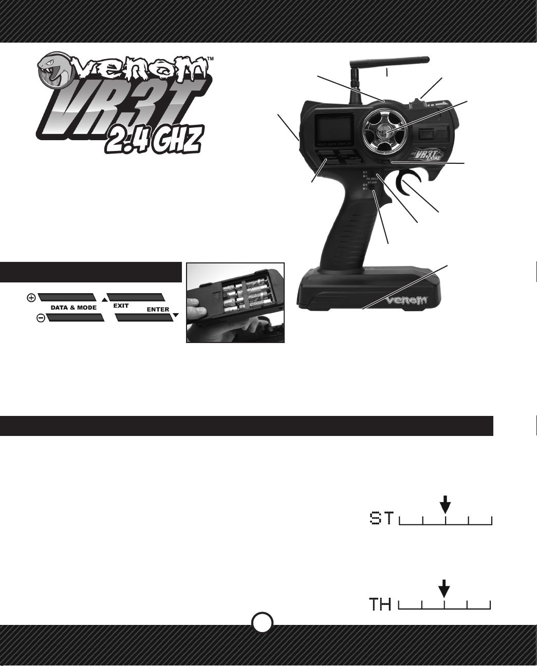
Thank you for purchasing the Venom VR3T 2.4 GHz
Transmitter. The VR3T 2.4 GHz Transmitter has all of
the great features of its FM predecessor including 3rd
Channel Mixing,16 Model Memory, and thumb switch
activated Programmable Steering Dual Rate, with the
stability and reliability of 2.4ghz technology. With the
freedom of 3rd Channel mixing, the VR3T 2.4 has
so many high-end features you won’t need to look
anywhere else for a 2.4ghz transmitter.
Navigation
Keys
Th. Hold
ST. D/R
Battery Box
TH. Trim
TH. Trigger
NAVIGATION KEYS
NOTE: Make sure the polarity of the 8 AA Alkaline
batteries are correct when they are put into the
transmitter.
In order for these settings to be programmed into the VR3T 2.4 the following steps must be followed.
1) All model components must be connected correctly. Starting with the receiver, servos, and power supply.
2) The steering and throttle trims on the VR3T 2.4 are set at neutral.
3) Always make sure to turn on the transmitter rst before turning on the receiver.
4) Make sure the transmitters antenna is installed for best input results.
1.0 STEERING TRIM
SETTING THE STEERING TRIM
Use the external trim button located above the Steering Wheel to make ne adjustments while driving your
model. During assembly of a new model or a repair use the Sub Trim feature; see section 2.3 TRIM (SUB
TRIM), to center the servo. Use the external trim button for small adjustments when operating a model.
SETTING THE THROTTLE TRIM
Use the external trim button located under the Steering Wheel to make ne adjustments while driving your
model. During assembly of a new model or a repair, use the Sub Trim feature; see section 2.3 TRIM (SUB
TRIM), to center the servo. Use the external trim button for small adjustments when operating a model.
1
Page 2
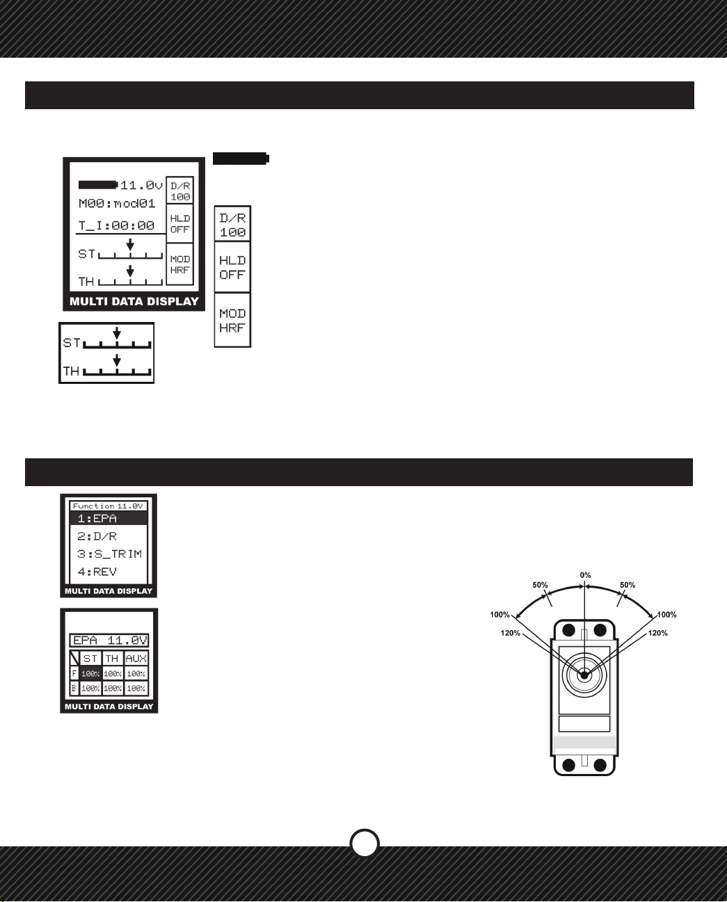
2.0 MAIN SCREEN
After the VR3T 2.4 has performed a system check when turned on the MAIN SCREEN will appear. This
screen displays important information about the battery voltage, settings and the model selected.
Represents a fully charged battery. This will start at 11.0 or higher depending
on the type of AA battery that is being used to power the transmitter (Alkaline/
Rechargeable NIMH). NOTE: When the battery has dropped below 8.4v an
alarm will sound.
Displays the current Steering Dual Rate value (see 1.3 - ST D/R Steering Dual Rate)
Displays the TH HOLD status as ON or OFF
(See 2.4 SYSTEM/HOLD (TH. HOLD)
Displays the transmitting mode
(See 2.1 SYSTEM / MOD (MODULATION)
The current position of the steering and throttle trims setting are displayed.
PROGRAMMING MODE
To enter programming mode from the Main Screen press the ENTER button on the transmitter. To save and
exit from the sub menu press EXIT.
2.1 FUNCTION / EPA (END POINT ADJUSTMENT)
End Point Adjustment (EPA) - Used to set the maximum travel of the desired function from
0-120%. Can be used to set both directions of travel (fwd/bk & lft/rt) to adjust the overall
range of movement or value. Can be used in conjunction with Dual Rate (see also Dual
Rate)
1) Press ENTER to see the FUNCTION MENU
2) Use the +/- KEYS to highlight EPA and press
ENTER.
3) Press ENTER to select a value.
4) Use the +/- KEYS to change the value.
5) Press EXIT to save and return to FUNCTION
MENU, press EXIT again to return to the
Main Screen.
NOTE: When using an electronic speed control
(ESC) set the Throttle EPA values to 120%. This
will allow the ESC to calibrate itself to the VR3T
2.4 and make the response and feel of the throttle
as smooth as possible.
LEFT
BACK
SERVO
TERMS: F-FORWARD, B-BACK, ST-STEERING, TH-THROTTLE, AUX-AUXILLIARY
2
RIGHT
FWD
Page 3
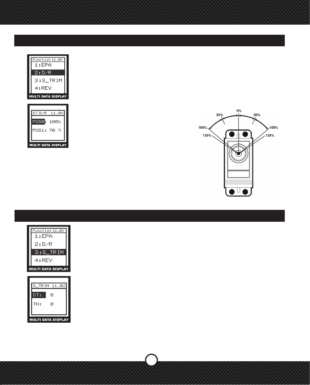
2.2 FUNCTION / ST D/R (STEERING DUAL RATE)
ST D/R - Steering Dual Rate (ST D/R) - Creates two overall steering travel presets. Set
the primary value POS0 to an equal or lesser percentage of the steering EPA. Set the
secondary value POS1 to a lower percentage than the primary value POS0. Use the
ST D/R button on the grip of the transmitter to select between the two preset values.
Example, if the EPA steering value is 100% then set POS0 to 100% (or less) and set
POS1 to 70%. When the ST D/R button is pressed the steering travel value changes
between 100% and 70% This allows you to change the amount of steering while
driving.
1) Press ENTER to see the FUNCTION MENU.
2) Use the +/- KEYS to highlight D/R and press
ENTER.
3) Press ENTER to select a setting.
4) Use the +/- KEYS to change the value.
5) Press EXIT to save and return to FUNCTION
MENU, press EXIT again to return to the
Main Screen.
TERMS: POS- POSITION
LEFT
BACK
RIGHT
FWD
SERVO
2.3 FUNCTION / S_TRIM (SUB TRIM)
The SUB TRIM feature allows for a function to be adjusted in 1% increments from the
center of travel point which is 0%. Use this to make small adjustments and to center a
servo during assembly. While driving, using the external TRIM BUTTONS for Steering
(ST) and Throttle (TH).
1) Press ENTER to see the FUNCTION MENU.
2) Use the +/- KEYS to highlight S_TRIM and press ENTER.
3) Press ENTER to select a setting.
4) Use the +/- KEYS to change the value.
5) Press EXIT to save and return to FUNCTION MENU, press EXIT again to return
to the Main Screen.
TERMS: ST-STEERING, TH-THROTTLE.
3
Page 4

2.4 FUNCTION / REV (REVERSE)
REV - REVERSE (REV) - This function is used to reverse the direction of movement or
action by a servo or speed control.
1) Press ENTER to see the FUNCTION MENU.
2) Use the +/- KEYS to highlight REV and press ENTER.
3) Press ENTER to select a setting.
4) Use the +/- KEYS to change the value.
5) Press EXIT to save and return to FUNCTION MENU, press EXIT again to return to the
Main Screen.
TERMS: F-FORWARD, B-BACK, ST-STEERING, TH-THROTTLE, AUX-AUXILLIARY
2.5 FUNCTION / ST. CURV (STEERING CURVE)
STEERING CURVE (ST. CURVE) - The Steering curve is used to change the sensitivity
of the steering servo around neutral without affecting the maximum servo travel. This
feature is helpful for taming down vehicles with sensitive steering. For new vehicles start
at 0% until the driving characteristics are known.
1) Press ENTER to see the FUNCTION MENU.
2) Use the +/- KEYS to highlight ST CURV and press ENTER.
2) Use the +/- KEYS to change the setting.
5) Press EXIT to save and return to FUNCTION MENU, press EXIT again to return to the
Main Screen.
Note: Adjustment range is -100% ~+100%, default is 0%. For faster steering use the (+)
button, for slower steering use the (-) button.
TERMS: LINE-LINEAR, EXP-EXPONENTIAL, M-MODE, L-LOW, H-HIGH, R-RATE
4
Page 5
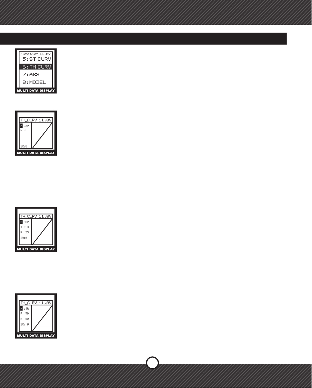
2.6 FUNCTION / TH. CURV (THROTTLE CURVE)
THROTTLE CURVE (TH. CURVE) - The Throttle Curve feature changes the response of
the throttle and the brakes. There are three different throttle curve types; EXP, VTR and
CUR. NOTE: The EXP is the only selection that creates an exponential curve for braking.
1) Press ENTER to see the FUNCTION MENU.
2) Use the +/- KEYS to highlight TH. CURV and press ENTER.
3) Press ENTER to select a setting.
4) Use the +/- KEYS to change the value.
5) Press EXIT to save and return to FUNCTION MENU, press EXIT again to return to the
Main Screen
EXP Curve
This feature is a simple exponential curve. Using the EXP feature will help smooth your
throttle response for vehicles with a touchy throttle.
1) Select EXP for the throttle curve mode.
2) Select the “R” (rate) to set the throttle curve rate by pressing ENTER
3) Use the (+) to make the throttle rate more sensitive. Use the (-) to make the throttle
rate less sensitive.
Brake Adjustments
This adjustment is the same for all three Throttle Curve types.
1) Select the BR setting with the ENTER button.
2) Use the (+) button to make braking more aggressive. Use the (-) to make the
braking more mild.
3) Press the EXIT button to return to the FUNCTION menu, and again to return to the
main screen.
CUR Curve
This feature has three adjustable throttle rate points through the throttle range that can be
independently adjusted.
1) Select CUR for the throttle curve mode.
2) Select the “R” (rate) to set the throttle curve rate by pressing ENTER. This will
highlight the (1) – First point.
3) Use the +/- buttons to adjust the rst point.
4) Press enter to go to the (2) – 2nd point
5) Adjust the (2) point with the +/- buttons
6) Press enter and repeat for the (3) – 3rd point
7) Press enter and set the braking rate. Refer to the section on Brake Side
adjustments in the EXP Curve section.
VTR Curve
This Feature is enables the user to make throttle curve steeper (or milder) in a specic
range by allowing two different throttle curve rates by changing the curve switching point.
1) Change the Curve Switching Point (P) by using the +/- buttons.
2) Press ENTER to select the throttle rate. (R)
3) Use the (+) button to make the throttle response quicker. Use the (-) button to make
the throttle response milder.
4) Press EXIT to save and return to the FUNCTION menu. Press EXIT again to return
to the main menu.
5
Page 6
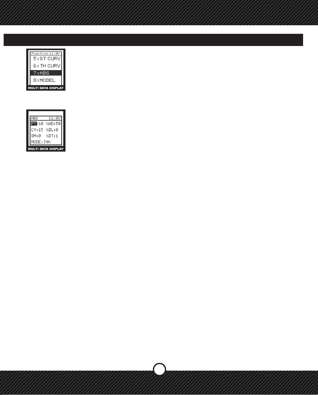
2.7 FUNCTION / ABS (ANTI-LOCK BRAKE SYSTEM)
The ABS feature is just like a real car in that the brakes will pulse intermittently when
they are applied to reduce the chance of a skid or in the case of a 4 Wheel Drive vehicle,
it will reduce under steer. The return amount, pulse cycle, and brake duty can be adjust-
ed. The ABS effective region can be adjusted as a function of the steering mix.
1) Press ENTER to enter the FUNCTION menu
2) Use the +/- Keys to select the ABS function and press ENTER
4) Press enter to select WC value. Us the +/- to change the value. Range 0%~100%
5) Press enter to select CY value. Us the +/- to change the value. Range 0%~100%
6) Press enter to select DL value. Us the +/- to change the value. Range 0%~100%
7) Press enter to select SM value. Us the +/- to change the value. Range 0%~100%
If this value is 0%, disable the Steering Mix . (See Section 2.13)
8) Press enter to select DT value. Us the +/- to change the value. Range 0%~100%
9) Press enter to select MODE. Us the +/- to change INH, TH, AUX, TH & AUX
NOTE: In MODE, if the INH is selected, the ABS feature is disabled. If TH is selected,
braking only occurs on the Throttle brake. If AUX is selected, braking only occurs with
the AUX channel. If TH & AUX is selected, braking occurs with both the Throttle and
AUX channels.
Terms:
PT - Operation Trigger Point
WD – Brake Return Amount. Sets the rate the servo returns versus trigger operation for
brake release.
CY – Cycle Speed. The smaller the set value, the faster the pulse cycle.
DL – Delay Amount. Sets the delay from brake operation to ABS. When set to 0%, the
ABS function activates without delay.
SM – Steering Mix
DT – Cycle duty ratio. Sets the proportion of time that the brakes are being applied and
released by pulse operation.
Mode: Sets the channel(s) that the ABS feature will operate on.
6
Page 7

2.8 FUNCTION / MDL (MODEL)
MDL - MODEL (MDL) - The Model Function used to choose one of the 16 model proles
available and create, edit and copy them as needed.
SEL - SELECT
1) Press ENTER to access the model memory.
2) Use the +/- KEYS to choose a model prole.
3) Press ENTER to save your selection.
4) Press EXIT to save and return to FUNCTION MENU, press EXIT again to return to
the Main Screen.
EDT - EDIT
1) Press ENTER to access the model prole.
SEL - SELECT
EDT-EDIT
CPY - COPY
2) Use the +/- KEYS to select the edit menu.
3) Use the +/- KEYS to type a new name for the prole.
3) Press to save your selection.
4) Press EXIT to save and return to FUNCTION MENU, press EXIT again to return to
the Main Screen.
CPY - COPY
1) Press ENTER to access the model prole.
2) Use the +/- KEYS to choose a model prole to copy onto another selected prole.
3) Press ENTER to save your selection.
4) Press EXIT to save and return to FUNCTION MENU, press EXIT again to return to
the Main Screen.
TERMS: F-FORWARD, B-BACK, ST-STEERING, TH-THROTTLE, AUX-AUXILLIARY
2.9 FUNCTION / SPEED
This function allows the speed of the Throttle Servo and Steering Servo to be set. In the
Steering Speed menu, the Turning Speed and the Return Speed can be set.
A. Steering Speed
1) Press ENTER to see the FUNCTION MENU.
2) Use the +/- Keys to select the ST function and press ENTER.
3) Press ENTER to select a setting.
4) Use the +/- Keys to change the value.
5) Press EXIT TWICE to save and return to the FUNCTION MENU, press EXIT again to
return to the main screen.
ST - STEERING SPEED
7
Page 8

2.9 FUNCTION / SPEED (CONTINUED)
B. Throttle Speed
1) Use the +/- Keys to select the TH function.
2) Press enter to select SPD. FL item. (See denitions below)
3) Use the +/- Keys to change the value.
4) Press EXIT TWICE to save and return to the FUNCTION menu.
TH-THROTTLE SPEED
Terms:
SPD.FL – Speed Forward Delay. Range: 0%~100%, default: 0%
SPD. BK – Speed Backward Delay. Range: 0%~100%, default: 0%
2.10 FUNCTION / ATS (AUTOMATIC START)
If full throttle is applied when starting on a slippery track, the wheels may spin and the car
will not accelerate smoothly. When the ATS system is activated, moving the throttle trigger
slowly will cause the throttle servo to switch from the set throttle position to a preset
point so the tires do not lose their grip and the car accelerates smoothly. This feature is
only effective for the rst throttle trigger operation when starting. It has to be activated
before every start. When the throttle trigger is released even slightly, the Start Function is
automatically deactivated and returns to normal throttle trigger operation.
TH-THROTTLE SPEED
1) Press ENTER to see the FUNCTION MENU
2) Use the +/- Keys to select the ATS function and press ENTER
3) Press ENTER to select TRI item. Use +/- to change the value. Range -100%~+100%
4) Press ENTER to select POS item. Use +/- to change the value.
Range -100%~+100%
5) Press ENTER to select DLY item. Use +/- to change the value. Range -100%~+100%
6) Press ENTER to select MOD item. Use +/- to change INH or RDY.
7) Press EXIT TWICE to save and return to the FUNCTION menu.
Terms:
TRI – Throttle Trigger Position
POS – Preset Position
DLY – ATS Delay Time
MOD – ATS Ready Setting
8
Page 9

2.11 FUNCTION / MODULATE
This is used to bind the VR3T to the 3 Ch 2.4ghz receiver.
NOTE: The Bind plug will be needed for this step.
1) Plug the Bind plug into channel 1 of the 3 Ch 2.4ghz receiver.
2) Turn on power to the 3 Ch 2.4ghz receiver.
3) Turn on the power on the VR3T transmitter.
4) Press ENTER to see the FUNCTION MENU.
5) Use the +/- Keys to select the MODULATE function and press ENTER.
6) Use the +/- Keys to select YES.
7) Press ENTER to bind the 3Ch 2.4ghz receiver to the VR3T Transmitter.
8) When it says SET OK, binding is complete.
BIND SCREEN
9) Press EXIT to save and return to the FUNCTION menu.
2.12 FUNCTION / BR_MIX (BRAKE MIX)
This is used to mix a secondary braking system run off the AUX channel with the throttle
channel. When using the secondary braking system, set the BRAKE MIX value to a
percentage of the Throttle Brake. When using a secondary braking system, it will control
the rear brakes with the front brakes being controlled by the throttle brake. The TH TRIM
and TH EPA is then used to ne tune the power and balance of the overall braking
system.
BIND SCREEN
1) Press ENTER to see the FUNCTION MENU
2) Use the +/- Keys to select the BK_MIX function.
3) Press enter to select a item.
4) Use the +/- Keys to change the value
5) Press EXIT TWICE to save and return to the FUNCTION menu.
Terms:
RATE – The rate of brake between the 3rd channel and the 2nd channel.
Range: 0%~120%, 0% default.
EN – Option to Enable the Brake Mix feature.
9
Page 10

2.13 FUNCTION / MIX ( MIXING )
MIX - MIXING - used to mix between functions for greater control of the model.
1) Press ENTER to see the FUNCTION MENU.
2) Use the +/- KEYS to highlight MIX and press ENTER.
3) Press ENTER to select a setting.
4) Use the +/- KEYS to change the value.
5) Press EXIT to save and return to SYSTEM MENU, press EXIT to return to the
FUNCTION MENU, press EXIT again to Main Screen.
TERMS: EN-ENABLE, ST-STEERING, TH-THROTTLE, AUX-AUXILLIARY,
2.14 FUNCTION / TH. HOLD ( THROTTLE HOLD )
Throttle Hold allows the Throttle Servo to be set to a percentage of the total travel range.
This is an alternative to using the choke on a gas motor when starting up a model.
This function locks out the normal use of the Throttle until the TH. HOLD button on the
transmitter is pushed again. Make sure the value is only set high enough to idle the motor
during starting and warm up. NOTE: Setting the Throttle Hold value too high may
cause a run away vehicle.
LOCATED ON THE RIGHT
SIDE OF THE TRANSMITTER
1) Press ENTER to see the FUNCTION MENU.
2) Use the +/- KEYS to highlight TH HOLD and press ENTER.
3) Press ENTER to select a setting.
4) Use the +/- KEYS to change the value.
5) Press EXIT to save and return to SYSTEM MENU, press EXIT to return to the
FUNCTION MENU, press EXIT again to Main Screen.
To use this setting while running the model press
the TH. HOLD button located to the left side of
the throttle trigger once. Doing so will enable the
TH. HOLD and put the throttle at the set value. To
release the TH. HOLD press it once more giving
full function to the TH.TRIGGER.
SERVO
10
Page 11

2.15 FUNCTION / F/S (FAIL-SAFE)
The Fail Safe feature is used to help prevent an out of control model caused by the
loss of a transmitter signal. If a loss of signal should occur the receiver will adjust the
steering or throttle or both to a preset value.
1) Press ENTER to see the FUNCTION MENU.
2) Use the +/- KEYS to highlight F/S and press ENTER
3) Press ENTER to select a setting
4) Use the +/- KEYS to change the value
5) Press EXIT to save and return to SYSTEM MENU, press EXIT to return to the
FUNCTION MENU, press EXIT again to Main Screen.
TERMS: EN-ENABLE, TH-THROTTLE, ST-STEERING,
2.16 FUNCTION / NEUTRAL
This function is used to calibrate the neutral center point of the of the Steering wheel
or Throttle trigger.
1) Press ENTER to see the FUNCTION MENU.
2) Use the +/- Keys to select the NEUTRAL function.
3) Use the +/- Keys to select YES.
4) Press ENTER to calibrate the neutral
5) Press EXIT TWICE to save and return to the FUNCTION menu.
Note: Do not move the Steering wheel or Throttle trigger during the calibration
process.
1) Press ENTER to see the FUNCTION MENU.
2) Use the +/- KEYS to highlight F/S and press ENTER
3) Press ENTER to select a setting
4) Use the +/- KEYS to change the value
5) Press EXIT to save and return to the FUNCTION MENU, press EXIT again to Main
Screen.
TERMS: EN-ENABLE, TH-THROTTLE, ST-STEERING,
11
Page 12

2.17 FUNCTION / SOUND
This function is used to turn the beeping tones ON or OFF on the Transmitter.
1) Press ENTER to see the FUNCTION MENU.
2) Use the +/- Keys to select the SOUND function.
3) Use the +/- Keys to select INH or ACT.
4) Press EXIT TWICE to save and return to the FUNCTION MENU.
2.18 FUNCTION / RESET
RESET - This function is used to reset the entire memory of the VR3T 2.4. All settings
will be reset to the factory default values.
1) Press ENTER to see the FUNCTION MENU.
2) Use the +/- KEYS to highlight the RESET box and press ENTER
3) Press ENTER to reset the VR3T 2.4 transmitter memory
4) Press EXIT to save and return to SYSTEM MENU, press EXIT to return to the
FUNCTION MENU, press EXIT again to Main Screen.
12
Page 13

2.19 FUNCTION / M_RES (MODEL RESET)
Model Reset feature is used to reset a specic model memory slot back to factory
default settings.
1) Press ENTER to see the FUNCTION MENU.
2) Use the +/- Keys to select the M_RES function and press ENTER.
3) Use the +/- Keys to select YES.
4) Press ENTER twice to reset the data.
5) Press EXIT TWICE to save and return to the FUNCTION menu.
2.20 FUNCTION / TIMER
Use the timer to monitor your race, lap times or test session. By default the Timer is
set to the INH (Inactive) Mode. Use the +/- Keys to set the mode to UP_T or DN_T to
activate the timer function. The UP_T setting will count up from zero to a user set time
limit or a maximum of 99 minutes 30 seconds. The DN_T setting will count down to zero
from a user set time limit or a maximum of 99 minutes 30 seconds. The timer will start
on the rst pull of the Throttle Trigger and will stop when full brakes are applied.
1) Press ENTER to see the FUNCTION MENU.
2) Use the +/- KEYS to highlight TIMER and press ENTER
3) Press ENTER to scroll through INH, UP_T and DN_T.
4) Press ENTER to set the timer in 30sec increments. Maximum time limit is 99 min, 30
sec.
5) Press EXIT to save and return to the FUNCTION MENU, press EXIT again to return
to the Main Screen.
13
Page 14

2.6 TRANSMITTER & RECEIVER SPECIFICATIONS
Transmitter Specs:
Part Numbers:VEN-8181 (USA), VEN-8182 (World)
Model: VR3T 2.4 GHz 3 Channel Transmitter
Specications: Computerized LCD
Code Format: PCM
Frequency: 2.4-2.483 Ghz
Channels: 3 (Steering, Throttle, Aux.)
Transmitting Power: 10mW (EU) (or 100mW)
DC Input: 9.6V, <200mA
Measurements:
Weight: 20 oz. / 560g with 8 AA Batteries
14
Venom 2.4GHz 3 Channel Receiver:
Part Number:VEN-8183
1) Channel 1: Throttle servo, ESC,
2) Channel 2: Steering servo, ESC
3) Channel 3: Servo, ESC, Optional
4) Channel 4: Battery (Power Supply)
Page 15

NOTES
15
Page 16

161718
Page 17

Page 18

MENU NAV KEY
Enter - Select in Item
DATA & MODE
EXIT
ENTER
Exit - Saves Value
+/- to select values and nav.
NOTE:
In order for these settings to be programmed into the VR3T 2.4 the following steps must be followed.
1) All model components must be connected correctly. Starting with the receiver, servos, and power supply.
2) The steering and throttle trims on the VR3T 2.4 are set at neutral.
3) Always make sure to turn on the transmitter rst before turning on the receiver.
4) Make sure the transmitters antenna is installed for best input results.
Page 19

FCC INFORMATION
Compliance with FCC regulations (Valid in U.S. only) This device complies with part 15 FCC rules. Operation
of this device is subject to the following two conditions:
1. This device may not cause harmful interference.
2. This device must accept any harmful interference that may cause undesired operation.
This device generates and uses radio frequency energy and if not used properly may cause interference to
radio and television reception. It has been tested and found to comply with the limits set by the FCC which are
designed to provide reasonable protection against such interference.
FCC Warning:
CAUTION: Venom™ is not responsible for any radio or TV interference caused by unauthorized modications
to this product. Changes or modications not authorized by Venom™ will void all warranties.
NOTE: This product has been tested and found to comply with the limits for a Class B digital device, compliant
to Part 15 of the FCC Rules. These limits are designed to provide reasonable protection against harmful
interference in a residential installation. This product generates, uses and can radiate radio frequency energy
and, if not installed and used as instructed, may cause harmful interference to radio communications. However,
there is no guarantee that interference will not occur in a particular installation. If this product does cause
harmful interference to radio or television reception, which can be determined by turning the product on and
off, correct the interference by trying one or more of the following measures:
- Reorient or relocate the receiving antenna.
- Increase the separation between the equipment and receiver.
- Connect the equipment into an outlet on a circuit different from the receiver.
- Consult the dealer or an experienced radio/TV technician for help.
FCC# XXXXXXXXXXXXX
Venom™ Limited Warranty
Venom™ warrants this product to be free of material and workmanship defects when new. If a component
is defective or was not correctly made, Venom™ will, at its sole discretion, repair or replace it free of charge
within 90 days from date of purchase. If you believe a defect became evident only after operation, please
contact us to discuss the situation.
A dated & itemized sales receipt must accompany any product returned for warranty work. Before returning
any product, please contact Venom™ Customer Service at 800-705-0620 to receive a Return Merchandise
Authorization Number (RMA#).
We guarantee this product to be free of manufacturing faults and material defects. This product has been
checked and adjusted individually before leaving the manufacturer. Please contact your local hobby shop
for replacement parts and technical support or contact Venom™ Customer Service at 800.705.0620 or
customerservice@venom-group.com.
19
Page 20

Copyright © 2009 by Venom™
Notice of Rights
All rights reserved. No part of this manual may not be reproduced or transmitted in any form by any means,
electronic, mechanical, photocopying, recording, or otherwise, without the prior written permission of Venom™.
For information on getting permission for reprints and excerpts, contact customerservice@venom-group.
com.
Notice of Liability
The information in this manual is distributed on an “As Is” basis, without warranty. While every precaution
has been taken in the preparation of the manual, Venom™ does not have any liability to any person or entity
with respect to any loss or damage caused or alleged to be caused directly or indirectly by the information
contained in this manual, or by the products described in it.
Actual product may vary from product shown. Product is subject to change.
Prop 65 Warning
This product contains chemicals known to the State of California to cause Cancer, Birth Defects and other
Reproductive Harm. Be responsible, dispose of properly.
Venom Group International
14028 N. Ohio Street
Rathdrum, ID 83858
Australia
PO Box 7325
Alexandria NSW 2015
Customer Service
800.705.0620
customerservice@venom-group.com
VEN-8181M-1
 Loading...