

Page 1
Venom Smart Temp / Fail Safe Instructions
Venom Smart Temp / Fail Safe Instructions
VEN-0605i-1
Pg. 1/4
Thank you for purchasing the Venom Smart Temp (VST). These instructions will help you navigate through the many
features of this advanced on-board monitoring system. Please take a minute and read through these instructions to
familiarize yourself with the Venom Smart Temp before installing and using it. A few minutes up front will make the installation
and programming easier to understand.
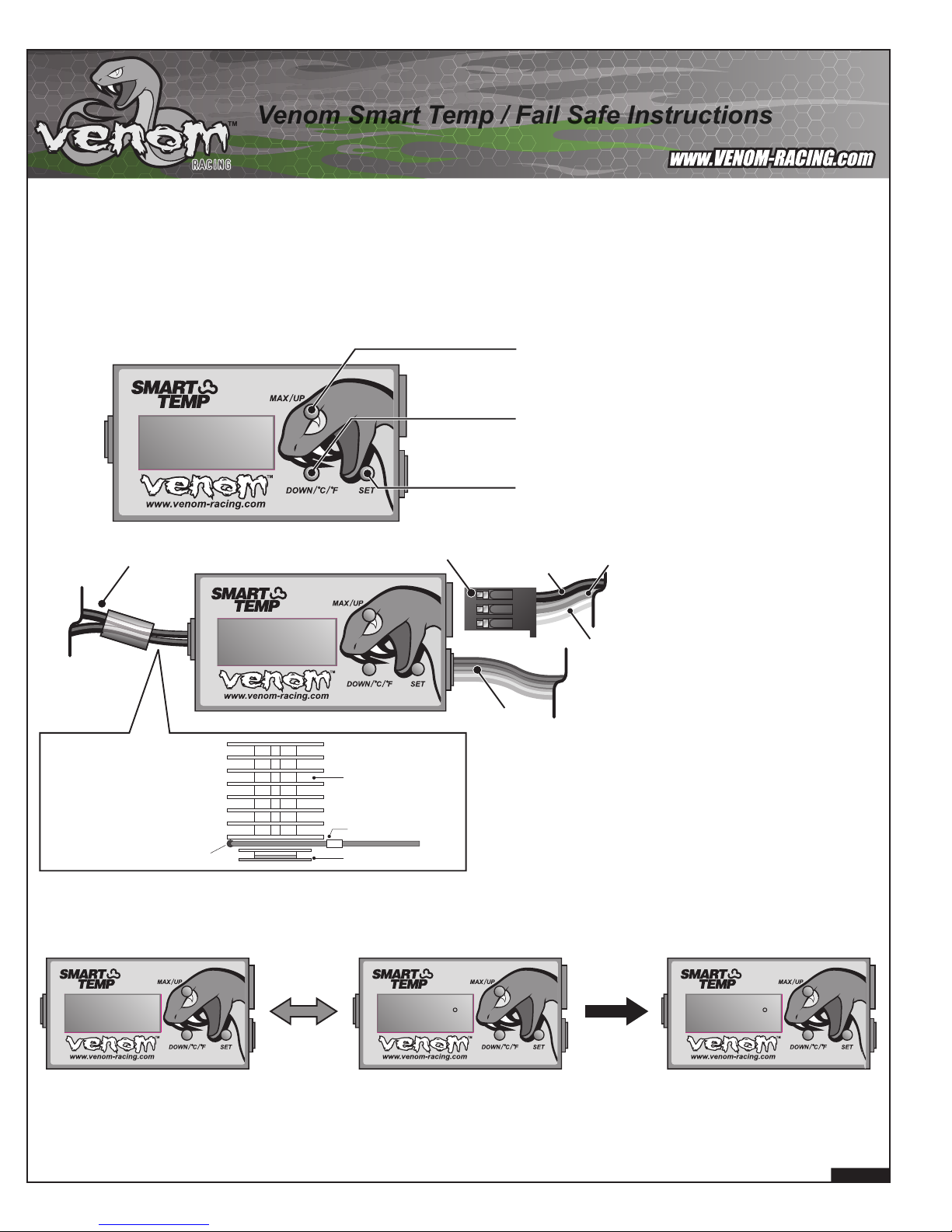
1. Getting to know your Venom Smart Temp / Fail Safe
Features:
• Current Engine Temp with Peak Temp Recall
• Overheat Fail Safe with Programmable Throttle Limiter
• Digital Volt Meter with Low Voltage Fail Safe
• Radio Fail Safe with Automatic Braking.
The smart temp is designed for 4.8 to 6.0 volt radio systems and
temperatures ranging between 122º-392ºF (50º-200ºC). Using
higher voltages and temperatures may damage the module and
void the manufacturer’s warranty.
MAX/UP
Press to see maximum temperature recorded
when in the main screen or to increase a value
during setup modes.
DOWN/ ºC/ ºF
Press to decrease a value during setup modes
or use to select between Celsius and Fahrenheit
temperature readings when in the main screen
.
SET
Press to scroll through setup screens and
sub menus.
Temperature Probe Loop
Engine Head
Note: For best results,
make sure the probe
loop is as close to the
bottom of the head as
possible and the red
portion is 90º-180º
away from the exhaust
port.
Probe Loop End
Crankcase
Red
From Throttle Servo
Negative (-)
Positive (+)
Signal (s)
To Receiver
021 c6.5v 070 f
2. Main Screen
The Main Screen switches every 5 seconds between Voltage and Temp Readings. To switch the Temp Reading from Celsius to
Fahrenheit and back, press the Down/ ºC/ ºF once when the Temp screen is displayed.
Note: When using the Venom Smart Temp, always turn the
transmitter on first, then the receiver.
5 seconds DOWN/ ºC / ºF
Page 2

3. Overheat Fail Safe (First Menu Screen)
The Venom Overheat Fail Safe is the best way to protect your nitro engine from serious damage that can occur when a nitro
engine overheats. Once the overheat temp is set, the VST will constantly monitor your engine temperature. In the event
the temperature exceeds the set temp, the VST will engage the Overheat Fail Safe and limit the percentage of throttle
available until the engine temperature drops 5º C (9º F) or more below the set point. After the temp drops below the set point,
the Overheat Fail Safe Mode will automatically disengage and return the model to its full operating potential.
Racers Note: The VST is a great tuning aid for monitoring peak temperatures during race prep and track testing but
the feature can be turned off for racing if desired (See Step 5).
• To access the Temperature Fail Safe Screen, press the SET button once.
• The Fail Safe temperature can be set in 5º C increments from 50-200 ºC or 9º F increments
SET
392 f
SET SET
from 122-392º F.
NOTE! REFER TO YOUR ENGINE MANUAL FOR RECOMMENDED SAFE OPERATING
TEMPERATURES FOR YOUR SPECIFIC ENGINE.
• To adjust the Overheat set temp, press the
• Please see Step 5 to set the Throttle Servo Limiter.
UP or DOWN button (Fig a).
c or f = Max Temp Fail Safe Setup Screen
(Fig a)
4. Voltage Fail Safe (Second Menu Screen)
The Voltage Fail Safe uses the same safety features as the Overheat Fail Safe but instead of monitoring engine temp,
it monitors the voltage of the receiver battery pack. The receiver battery pack supplies power to all of the on-board electronics
on your model, including the servos. If the voltage of the receiver pack drops too low, the system will not have enough power
to signal the servos and they will “stick” in the position of the last signal received. If the last signal was wide open throttle, the
car will become an out of control safety hazard. After you set the minimum safe voltage using the instructions below, the VST
will constantly monitor the receiver battery pack voltage. If the system records two consecutive voltage readings below the
minimum safe voltage, the Voltage Fail Safe will be activated. When the VST records the first voltage reading above the
minimum safe voltage, it will disengage the voltage fail safe function and return the model to it’s full operating potential.
• To access the Voltage Fail Safe Screen, press the SET button twice.
SET
4.2 v
SET
• The Voltage Fail Safe can be set in 0.1 volt increments from 3.0 to 5.4 volts.
NOTE! Venom recommends a setting of no less than 4.2 volts.
• To adjust the low voltage set value, press the
• Please see Step 5 to set the Throttle Servo Limiter.
NOTE! The VST Voltage Fail Safe will not engage if there is a total battery failure
(ex. battery falls out of the model during a crash).
UP or DOWN button.
v = Voltage Fail Safe Setup Screen
5. Throttle Servo Limiter for Temperature / Voltage Fail Safe (Third Menu Screen)
In the Throttle Servo Limiter screen, the VST can be programmed to reduce the amount of throttle available during a Low
Voltage or Overheat situation. When either the Voltage Fail Safe or Overheat Fail Safe is engaged, the VST will
reduce the maximum throttle available to your choice of 20%, 40%, 60%, 80%, or 99% of normal throttle limit.
Racers Note: If you wish to effectively disengage the voltage and temperature fail safe options, set the throttle throw
percentage to 99%.
• To access the Throttle Servo Limiter menu,
press the SET button three times.
SET
60 P
SET
• To adjust the throttle percentage value,
press the up or down button.
• The number refers to the percentage of full
servo travel that will be available when
the fail safe is activated (See Fig b).
• The value can be set to 20%, 40%, 60%,
80%, or 99%.
p = Throttle Servo Limiter Setup Screen
Fig b
40%
20%
Idle
0%
Brakes
60%
80%
99%
Full Throttle
100%
Note:
Drawing is for reference
only. Your Servos and
their functioning may
vary.
Pg. 2/4
Page 3

6. Radio Fail Safe (Fourth Menu Screen)
The Radio Fail Safe monitors for radio signal failure. A loss in radio signal can result in an uncontrollable model. If the VST
detects a loss of radio signal, the Radio Fail Safe will engage and the brakes will be applied. Note! Follow the instructions
below to ensure the VST applies the proper amount of brakes for your specific model.
• To access the Radio Fail Safe Screen, press the SET button four times.
• To set the amount of brakes applied by the throttle servo when the Radio fail safe is engaged:
• First turn the radio off.
SET
16 F
SET
f
= Radio Fail Safe Setup Screen
• Starting at 16 in the Radio Fail Safe Screen (which should be close to neutral for your model),
adjust the number setting up or down until the Throttle servo reaches full brakes.
• The Radio Fail Safe position can be set from 1-32. Whether 1 is full brakes or full throttle depends
on the servo reverse settings (See Step 8).
• Press the
for the radio fail safe. Press the UP or DOWN buttons to turn
SET button once to move to the next menu screen and ensure ON is selected
ON or OFF.
NOTE! To test the Radio Fail Safe settings, begin by turning your radio on and checking that
the Throttle servo is in the neutral position and the Radio Fail Safe is turned on (See Step 7).
If the Throttle servo moves to full brakes when you turn your radio off, your Radio Fail Safe is
set correctly!
7. ON/OFF Function for the Radio Fail Safe (Fifth Menu Screen)
• To access the ON/OFF Radio Fail Safe Screen, press the SET button five times.
• Press the up or down button to set the Radio Fail Safe feature ON or OFF.
• This Function selects whether or not the Radio Fail Safe will be activated in the event of a Radio
SET
SET
=
Radio Fail Safe On/Off Screen
Signal Failure.
• If the system is set to ON, the Radio Fail Safe will be activated and the throttle will be moved to the
position set in the previous screen in the event of Radio Signal Failure.
• If the system is set to OFF, the Radio Fail Safe will be deactivated and the fail safe will not control the
servo in the event of a Radio Signal Failure. The Throttle will stay in the last position recorded
when the failure occurred, or may behave erratically depending on the nature of the fault.
NOTE! Venom Racing highly recommends always using the radio fail safe feature to protect
your model from serious damage that can occur from radio signal loss.
8. Set Control Direction for Voltage / Temperature Fail Safe (Sixth Menu Screen)
Depending on your model, your throttle servo increases the throttle in a clockwise or counter-clockwise direction. Choose one of the
following settings to set the VST to your model’s specific servo direction.
• To access the Control Direction menu, press the SET button six times.
• Press the UP and DOWN buttons to select one of the 3 following settings:
Setting 1 (Forward / Normal Servo Direction)
•During Low Voltage or Overheat Fail Safe activation, this setting will limit one direction of the servo
SET
movement to the Throttle Limiter Percentage set in Step 5. The opposite direction will still retain
100% of its movement (ex. 60% Throttle, 100% Brakes)
100%
Brakes
Fig c
Setting 2 (Reverse Servo Direction)
• This setting uses the same features as Setting 1 but reverses the direction.
SET
Fig d
100%
Full Throttle
60%
Throttle
Setting 3 (Advanced Throttle / Brake Setting)
• This feature limits both Throttle and Brake servo functions when the Overheat or Low Voltage
SET
Fail Safe is engaged.
• This is an advanced feature for special applications.
100%
Brakes
60%
Brakes
NOTE! This is similar to the servo reversing function on most radios.
0%
Neutral
0%
Neutral
0%
Neutral
60%
Throttle
60%
Throttle
100%
Full Throttle
100%
Brakes
100%
Full Throttle
If your Throttle Servo does not
function like the diagram in (Fig c),
use Setting 2 (Fig d) to reverse the
direction.
SET
c = Servo Control Direction Setup Screen
3/4
Page 4

9. Voltage / Temperature Fail Safe Test Mode (Seventh Menu Screen)
This screen allows you to test your Low Voltage / Overheat Fail Safe setting without having to use a flat battery or heat source
to trip the unit into fail safe mode.
• To activate the fail safe test mode press the SET button seven times until the “set t” screen appears.
• Press UP or DOWN to select ON.
SET
Warranty Service and Support
Thank you for purchasing the Venom Smart Temp / Fail Safe. We want to assure you that all of our products are backed by first-class customer service and
support. If you have any questions or concerns about the VST, please call our Customer Service Department toll free at 800-705-0620, Monday-Friday,
9:00am - 5:00pm Pacific Standard Time. You can also email us at customerservice@venom-racing.com. For hands on service and faster access to
replacement parts, please visit and support your local hobby shop.
Replacement Parts
The following replacement part is available at your local hobby shop or online at www.venom-racing.com.
• VEN-0600P Temperature Monitor Wire Loop Probe
• Turning this feature ON simulates a fail safe activation for approximately 20 seconds.
• With the radio on and full throttle applied, check to make sure the Throttle Limiter is properly reducing
the servo travel according to the settings you chose (20%, 40%, 60% 80%, or 99%) in Step 5.
• Change settings if required.
• After approximately 20 seconds the Fail Safe Test Mode will automatically reset to OFF.
Repair
If your product requires factory repair, please call or email our Customer Service Department in advance to receive a Return Authorization Number, the
correct shipping address and an estimate for work if required. When sending in product for repair:
• Write the Return Authorization Number on the outside of the package.
• Include your name, address, and daytime telephone number on a piece of paper inside the package.
Note: We cannot return ship to P.O. Boxes.
• Include a short summary of the problem.
Limited Warranty
Venom Racing warrants this product to be free of material and workmanship defects for a period of ninety (90) days from the date of purchase.
Because this is a high performance product and is intended to be used over a wide range of operating conditions and situations, Venom Racing does not
offer any warranty, express or implied, that covers damage caused by normal use or wear, or cover or imply how long any component of this product will last
before requiring replacement due to wear. The Venom Smart Temp is designed to be used as a tuning aid and a warning device. Because this product is
used over a wide range of operating conditions and situations,Venom Racing shall not be held responsible nor warrants any damage to your model, it’s
engine or components that are damaged due to excessive temperature, low voltage, radio signal failure or user error.
Any and all warranty coverage does not cover replacement parts and components damaged by water, neglect, improper use, chemical damage, crash
damage, or unauthorized product modifications associated with this product.
Venom Racing and affiliates, partners and subsidiaries cannot control the use, application or installation of this product and shall not be held liable for any
property damage or personal injury resulting from the improper use of this product.
Venom Racing
North America
Tel 800.705.0620
Fax 800.705.0621
Australia
Tel 61.2.9666.6944
Fax 61.2.9666.6955
Pg. 4/4
Customer Service email:
customerservice@venom-racing.com
 Loading...