

Page 1
BALANCE CHARGER/DISCHARGER
FOR NICD/NIMH/LITHIUM/PB BATTERIES
OPERATING MANUAL
[
dual power
]
AC 100V–240V | DC 11.0V–18.0V
Page 2

Thank you for purchasing the Venom Pro2 Charger. This is
a mulit-chemistry capable, rapid charger / discharger and
cell balancer with built in microprocessor. Please read and
understand the entire manual before operating the charger.
Notes:
Page 3

CONTENTS
SECTION PAGE
1. Features 1
2. Exterior of the unit 3
3. Warnings & Safety Notes 4
4. Programs Flow Charts 6
5. User Set Up 7
6. Charging Lithium Batteries 9
6.1 Charging Lithium Batteries in Balance Mode 10
6.2 “Fast Charging” Lithium Batteries 11
6.3 “Storage Mode” for Lithium Batteries 11
6.4 Discharging Lithium Batteries 12
6.5 Balancing Lithium Batteries During Discharge 12
7. NiMH / NiCd Battery Programs 13
7.1 Charging NiMH & NiCd Batteries 13
7.2 Discharging NiMN & NiCd Batteries 13
7.3 Cycling NiMN & NiCd Batteries 14
8. Pb Battery Programs 14
8.1 Charging Pb Batteries 14
8.2 Discharging Pb Batteries 15
9. Internal Resistance Testing Programs 15
10. Saving Data Programs 15
11. Loading Data Programs 16
12. Various Messages During Charging & Discharging 17
13. Warning & Error Messages 18
14. Specifications 19
15. Warranty and Service 19-20
Page 4

1
667
1. FEATURES
High Power Charging Circuit
The Venom Pro2 charger features a powerful
50-Watt charging circuit. The charger can safely
charge or discharge up to 15 cells of NiMH or
NiCd batteries and up to 6S LiPO batteries.
Optimized Operating Software
When charging or discharging, the Venom Pro2
charger features an “AUTO” function that will set
the output charging current automatically. This
feature is especially useful for Lithium Polymer
( LiPO ) batteries to reduce the possibility of
overcharging or discharging your batteries.
Integrated Inputs
The charger features easily accessible inputs on
the sides of the charger for receiver, transmitter
and igniter outputs, and balance blocks.
Page 5
2
© Venom Group International 2013
Multiple Balance Cycles
The Venom Pro2 Charger can monitor and
balance individual cells within a LiPO battery in
either charge or discharge mode.
Multiple Chemistry Charging
The Venom Pro2 charger will charge NiMH / NiCd,
LiLo, LiPO, LiFe and Pb battery types.
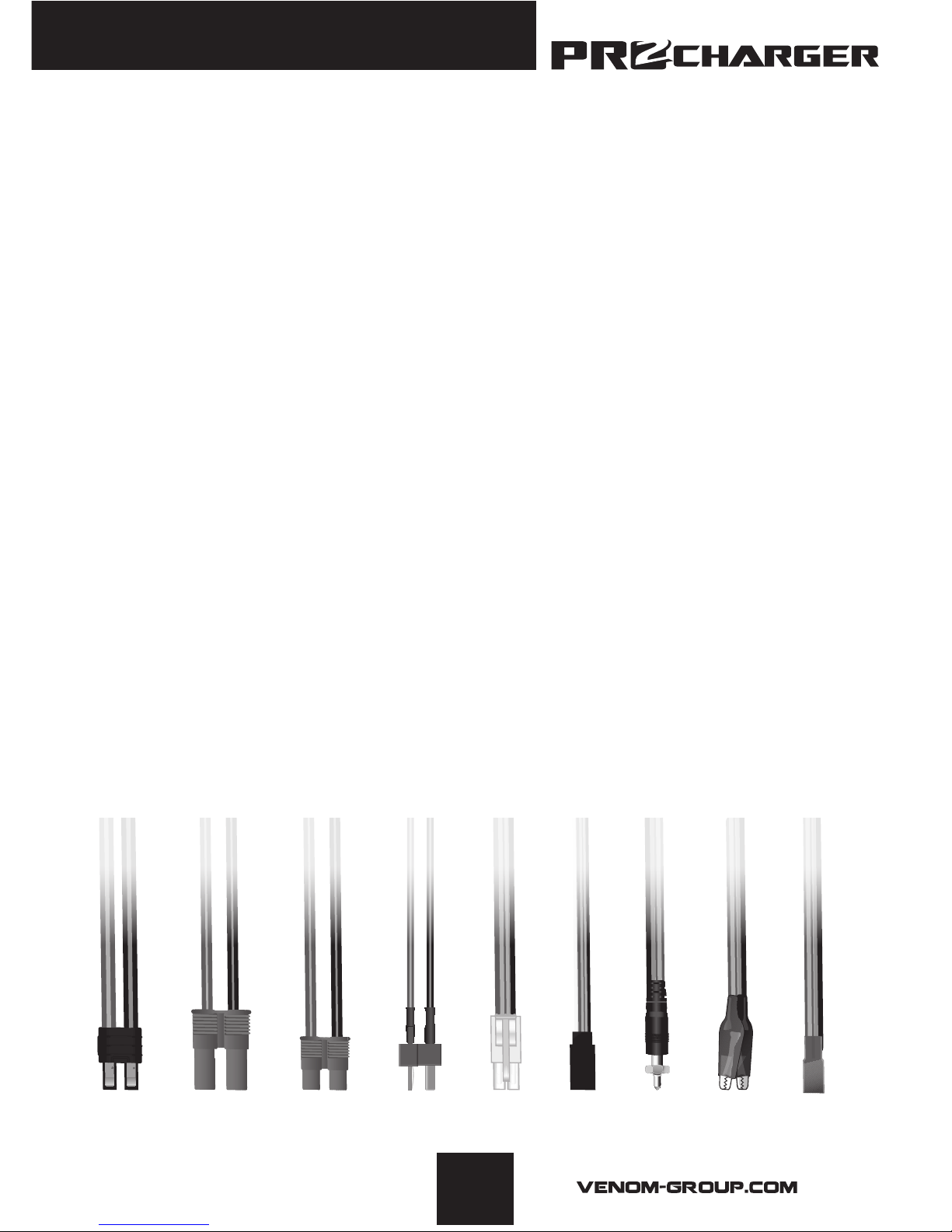
Multiple Charging Leads Included
The charger comes with the following charging
leads to cover the most common connection
types.
Receiver Plug
Glow Plug
Alligator Clips
Tamiya Plug
JST Plug
Deans Plug
Traxxas® Plug
EC3 Plug
EC5 Plug
Page 6
3
667
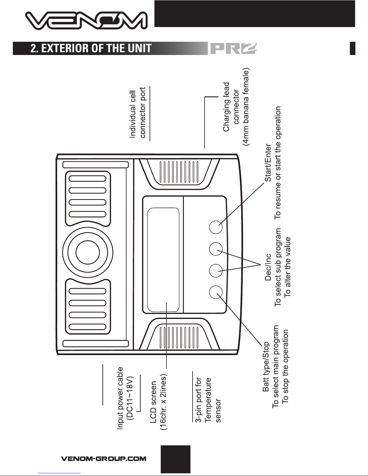
Input power cable
(AC100-240V)
2. EXTERIOR OF THE UNIT
Page 7
4
© Venom Group International 2013
3. WARNINGS AND SAFETY NOTES
• Never leave the charger unsupervised when it is connected to its power supply. If any
malfunction is observed immediately terminate the process and refer to the operation manual.
• Keep the charger away from dust, dampness or rain, heat, or direct sunshine and vibration.
• The circuit of the unit is designed to be powered by a 10-18V DC only.
• This unit and the battery to be charged or discharged should only be set upon a heat resistant,
non-ammable and non-conductive surface. Never charge on a car seat, carpet or similar
surface. Keep all ammable or volatile materials well away from operating area.
• Be sure to understand the specications of the battery to be charged or discharged. If the
program is set up incorrectly the battery can severely be damaged. Lithium batteries when
improperly charged, can cause permanant damage or re.
• To avoid short-circuits between the charge lead, always connect the charge cable to the unit
first and only then to the battery to be charged or discharged. Reverse the sequence when
disconnecting.
• Do not attempt to disassemble battery packs.
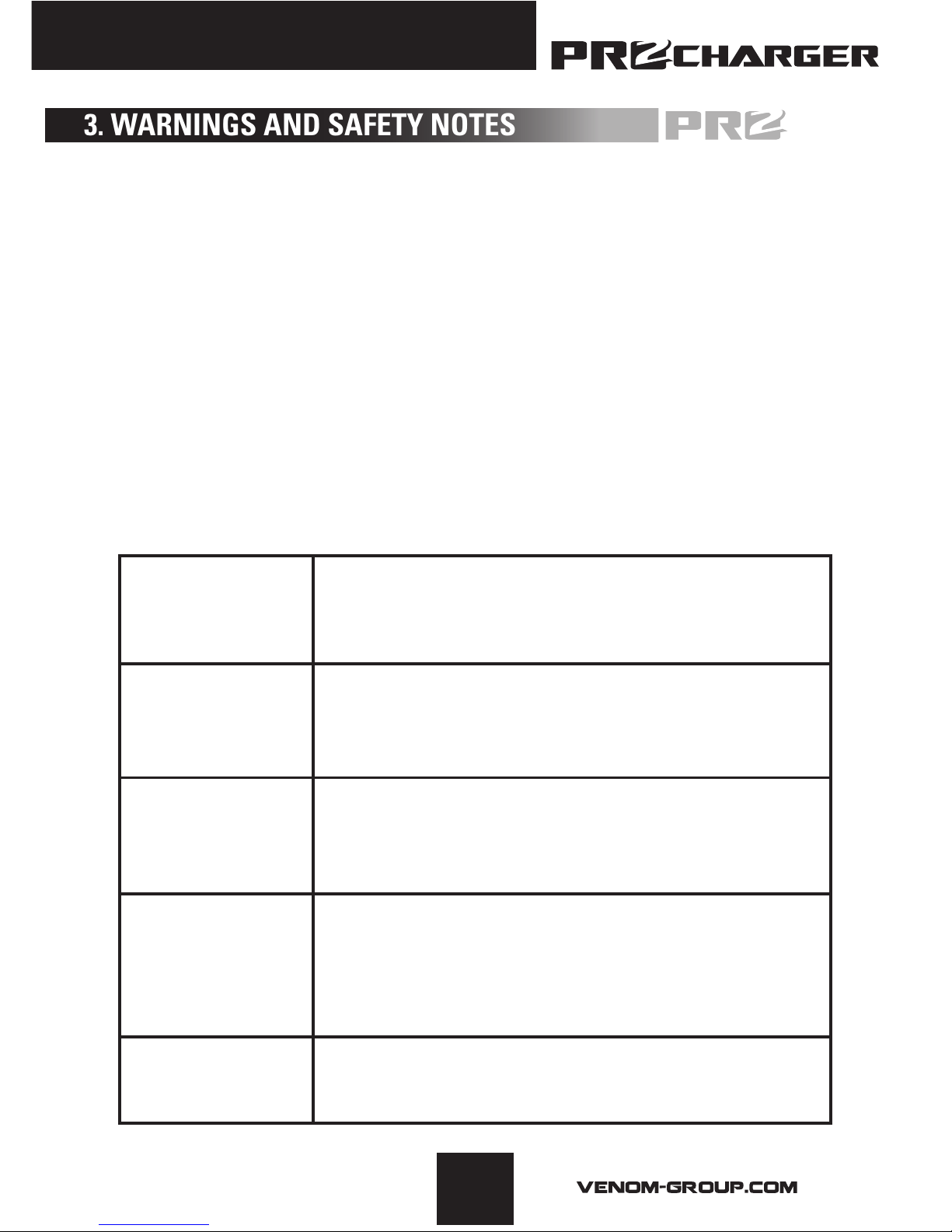
NiCd/NiMH
Lilo
LiFe
LiPo
PB
voltage level:1.2V/cell
allowable fast charge current:1C~2C depends on the
performance of cell discharge voltage cut off level
0.85V/cell(NiCd), 1.0V/cell(NiMH)
voltage level:3.6V/cell
max.charge voltage:4.1V/cell
allowable fast charge current: 1C or less
min.discharge voltage cut off level:2.5V/cell or higher
voltage level:3.3V/cell
max.charge voltage:3.6V/cell
allowable fast charge current: 4C or less(e.g. A123M1)
discharge voltage cut off level:2.0V/cell or higher
voltage level:2.0V/cell
voltage level:3.7V/cell
max.charge voltage:4.2V/cell
allowable fast charge current: 1C or less
discharge voltage cut off level:3.0V/cell or higher
(Lead-acid) max.charge voltage:2.46V/cell
allowable fast charge current:0.4C or less
discharge voltage cut off level:1.50V/cell or higher
Page 8

5
667
3. WARNINGS AND SAFETY NOTES
Pay close attention and verify the capacity and the voltage of the Lithium battery
pack to be charged or discharged. It may be composed of parallel and series
connection mixed. In parallel link the capacity of the battery pack is multiplied by
the number of cells but the voltage remains the same. Extreme voltage imbalance
can cause a fire or explosion during the charge process. We recommend you
congure the Lithium battery pack in series only.
Discharge
• The typical purpose of discharge is to determine the residual capacity of
the battery,or to lower the voltage of battery to a dened level. Much like the
process of charging, when you discharge batteries you must not leave the battery
unattended. To avoid the battery becoming deep-discharged, set the nal discharge
voltage correctly. Lithium batteries should not be deep-discharged to lower than
the minimum voltage, as this leads to a rapid loss of capacity or a total failure.
Generally, you do not need to discharge a Lithium battery.
• Some rechargeable batteries are said to have a memory effect. If they are partly
used and recharged before the whole charge is drawn out, they ‘remember’ this and
next time will only use that part of their capacity. NiCd and NiMH batteries are said
to suffer from memory effect. They prefer complete cycles; fully charge, then use
until empty, do not recharge before storage-allow them to self discharge during
storage. NiMH batteries have less memory effect than NiCd.
• Lithium batteries prefer a partial rather than a full discharge. Frequent full
discharges should be avoided if possible. Instead, charge the battery more often or
use a larger capacity pack.
• A brand-new NiCd battery pack will not reach peak performance until the pack has
been cycled approximately 10 times. The cyclic process of
charge and discharge will optimize the capacity of battery pack.
These warnings and safety notes are VERY important. Please follow the instructions
for maximum safety; misuse can result in damage to the charger and battery. In
extreme cases, improper use can result in bodily injury or property damage.
Page 9
6
© Venom Group International 2013
PROGRAM SELECT
SAVE DATA
SAVE DATA
Start
Enter
PROGRAM SELECT
LOAD DATA
LOAD DATA
Start
Enter
Start
Enter
Key Beep
Buzzer
Input Power Low
Cut-Off
INC
DEC
Battery Pack IR
231mΩ
INC
DEC
Test LiXX Internal
Resistance
Measurin g IR
WAIT DLEASE...
1:026 050 044
mΩ
4:039 042 044
mΩ
INC
DEC
PROGRAM SELECT
Pb BATT
Pb DISCHARGE
Pb CHARGE
Start
Enter
INC
DEC
LIXX DISCHARGE
PROGRAM SELECT
NiMH BATT
NiMH CHARGE
'Aut' / 'Man'
NiMH DISCHARGE
NiMH CYCLE
Start
Enter
INC
DEC
INC
DEC
PROGRAM SELECT
Nicd BATT
N
icd
CHARGE
'Aut' / 'Man'
N
icd
DISCHARGE
Nicd CYCLE
Start
Enter
INC
DEC
INC
DEC
Capacity Cut-Off
Safety Timer
Temp Cut-Off
USB Enable
INC
DEC
INC
DEC
Waste Time
CHG>DCHG
INC
DEC
USER SET
PROGRAM
LIXX V. Type
Lilo / LiPo / LiFe
CHK Time
NiMH Sensitivity
D. Peak
Nicd Sensitivity
D. Peak
Start
Enter
INC
DEC
INC
DEC
INC
DEC
PROGRAM SELECT
LIXX BATT
LIXX CHARGE LIXX BALANCE
LIXX FAST CHG LIXX STORAGE
Start
Enter
INC
DEC
INC
DEC
INC
DEC
INC
DEC
INC
DEC
Batt type
stop
Batt type
stop
Batt type
stop
Batt type
stop
Batt type
stop
Batt type
stop
INC
DEC
Batt type
stop
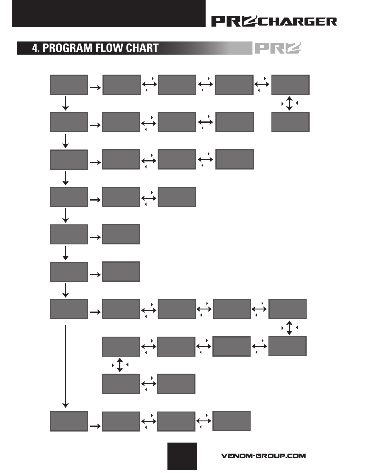
4. PROGRAM FLOW CHART
Page 10

7
667
The Charger will use the default values upon being powered up for the first time.
The Screen displays the following information in sequence and the user can change
the values of each parameter
To change the default values, press the Start/Enter key once. The value to be
adjusted will blink indicating it can be edited. Use the Inc/Dec keys to adjust the
value to the desired setting, then press the Start/Enter key once to save your
changes for that value.
The screen will show the nominal voltage of
the three types of Lithium batteries; LiFe (3.3V),
Lilo (3.6V), and LiPo (3.7V). It is very important
to make sure you choose the correct type of
battery during set up. Refer to the battery’s
owner manual for reference if needed. Failure
to choose the correct battery type can cause
damage to the battery, charger and will void all
warranties.
The charger will recognize the cell count of
Lithium batteries automatically at the beginning
of the charge or discharge cycle and compare
it to the settings selected. If a voltage has been
selected that is different from the voltage it
detects, an alarm will sound.
Over discharged batteries MAY be detected as a lower cell count pack. Always
conrm your setting before starting a charge sequence. Using the “CHK TIME”
parameter in your LiPo/Lilo/LiFe settings can allow you to delay detection in an
attempt to bring a dead battery back to life. YOU MUST USE EXTREME CAUTION
WHEN DELAYING CELL DETECTION. A 10 minute delay is suggested for larger mAh
packs, but small capacity batteries may nish charging/discharging before the 10
minute mark which could result in catastrophic failure of the battery. If there are any
doubts on how to use this feature, please contact Venom directly.
5. INITIAL USER PARAMETER SET UP
Page 11
8
© Venom Group International 2013
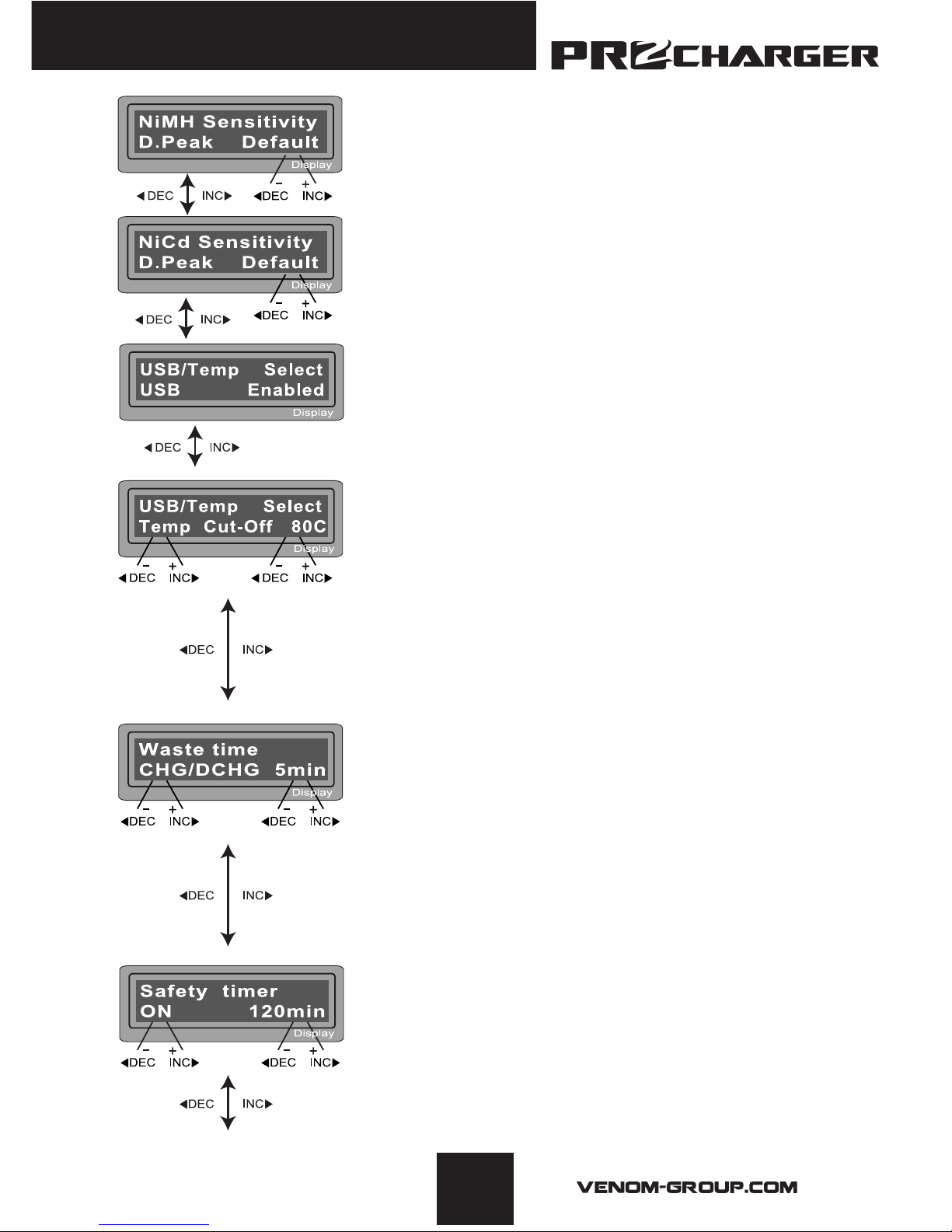
This shows the trigger voltage for automatic peak
detection of NiMH and NiCd battery. The effective
value ranges from 5 to 20mV per cell. If the trigger
voltage is set higher, there is a danger of overcharging
the battery; if it is set lower, there is a possibility of
premature termination. Please refer the technical
specication of the battery.(NiCd default:12mV, NiMH
default:7mV)
You can select the function of the 3-pin port on the
left side of the unit. It can be used as a temperature
sensor port, selected at this screen. If the port is
assigned as a temp. port, an optional temperature
probe contacting the surface of battery can be used.
You can set the maximum temperature at which the
charger should allow battery to reach during charge.
Once a battery reaches this temperature during
charge, the process will be terminated to protect the
battery. This charger does not connect to your PC.
When performing a charge/discharge or discharge/
charge cycle, your battery can often become warm
after the charge or discharge period. The “waste
time” setting will insert a time delay to occur after
each charge and discharge process to allow the
battery adequate time to cool down before being
starting the next process. The value ranges from 1 to
60 minutes.
Every charge is monitored by a safety timer. The
default setting is 120 minutes or 2 hours. Once this
time limit is reached the charger will stop charging
regardless if the charge is complete. This is
programmed to prevent overcharging of the battery if it
proves to be faulty, or if the termination circuit cannot
detect the battery is full. The value for the safety timer
should be long enough to allow a full charge of the
battery. When your charge completes, if the charger
says “TIME” in the upper right corner of the screen,
your charge was terminated due to the safety timer.
Page 12

9
667
Use these programs only when charging a lithium battery (Lilo/LiPo/LiFe) with a nominal voltage of 3.3V, 3.6V
or 3.7V per cell, respectively. The charge current going into the battery will vary depending on the chemistry
type so it is VERY IMPORTANT that you select the correct type for your battery. The ending voltage of the
charge is also important as it varies for all three types: 4.2V for LiPo, 4.1V for Lilo and 3.6V for LiFe. The charge
current (how many Amps you are putting into the pack) and nominal voltage (Proper voltage for the cell count
of the battery you are charging.) must be correct for the battery to be charged. To change these settings,
press the START/ENTER key to make the selected value blink. Using the increase and decrease buttons, set
your desired amperage, then press START/ENTER to save the setting. You will then be asked to select your
nominal voltage/cell count. Again, use the increase/decrease buttons to reach your desired setting and Press
the START/ENTER button to confirm and save.
Now, double check the charge settings. The upper left corner of the
screen should read the specific battery chemistry you are trying to
charge. In the case of the example, LiPo. The value underneath the
chemistry type is the charge current. Check your batteries specications
for proper charge rating, but with all Venom batteries, we recommend a 1C
charge rate. If your battery is a 5000mAh, your charge current should be
5.0. If using a 2200mAh pack, the charge rate would be 2.2. Simply placing
a decimal point after the first number in your capacity rating will give
the correct 1C charge rating. To further elaborate, a 2C charge rate on a
5000mAh pack would be 10.0.
The information on the right side of the screen will tell you which type of charge you are using and the voltage
and cell count you are attempting to charge. Remember, THIS VALUE MUST BE SET TO PROPERLY CHARGE
YOUR BATTERY.
When you are ready to charge, press and HOLD the START/ENTER button for 3 seconds.
6. CHARGING A LITHIUM BATTERY
(LILO/LIPO/LIFE) PROGRAM
This setting allows you to change the maximum capacity that
will be supplied to the battery during charge. If the nominal
pack voltage is not detected and the safety timer does not
expire for any reason, this feature will automatically stop the
process at the selected capacity value.
The Key beep/buzzer settings allow you to turn off the individual button “beep” as well as the musical tone that is used
to alert different mode changes.
When connecting the charger to a 12volt power source
(lead acid battery) in the eld, this setting will allow you to
monitor the incoming voltage. Should the voltage drop below
the value selected, the charger will terminate operation to
protect the input battery.
Page 13

10
© Venom Group International 2013
The next screen will ask to conrm the settings after the charger examines
the battery, giving a cell count. The “R:” value shows the number of cells
detected by the charger. The “S:” value shows the number of cells you
selected in the previous menu screen. If the “R:” value does not match
the “S:” value, the charger is seeing a different cell count than you have
selected. If this happens, press the Batt Type/Stop button to check the
number of cells you have selected. If this is correct compared to the battery,
you may have a problem with your battery. If the values are the same, it is
safe to charge at this point. Press and hold START/ENTER to start the Charge
sequence.
When charging, the screen provides useful information like the charge rate,
number of cells being charged, battery voltage and the amount of mAh, or
capacity that the charger has put into the pack being currently charged.
Press Batt type/Stop to stop the charging process at any time.
6.1 CHARGING LITHIUM BATTERIES IN BALANCE MODE.
Lithium batteries comprised of more than one cell will need to be balanced occasionally to ensure the best
possible performance. When balancing you MUST connected the supplied balance board to the charger and
then connect the balance lead from the battery to the board. The red and black positive and negative charge
leads will still need to be connected to the battery. The “balance” lead simply allows the charger to monitor
each individual cell. When “balance” charging, the charger will monitor each individual cell attempting to
bring them all to the same nominal voltage.
Like a standard charge sequence, the value in the lower left corner of the screen is the selected charge
current, in the lower right, the voltage of the pack that will be charged. To change these values, press the
START/ENTER key to cycle through the adjustable settings. Use the increase/decrease buttons to change
the values and use the START/ENTER button to confirm the values set. When
ready to BALANCE charge, press and hold the START/ENTER button for 3
seconds to start the process.
The next screen will ask to conrm the settings after the charger examines
the battery, giving a cell count. The “R:” value shows the number of cells
detected by the charger. The “S:” value shows the number of cells selected
in the previous menu screen. If the “R:” value does not match the “S:” value,
the charger is seeing a different cell count than what has been selected. If
this happens, press the Batt Type/Stop button to check the number of cells
selected. If this is correct compared to the battery, there may be a problem
with the battery. If the values are the same, it is safe to charge at this point.
Press and hold START/ENTER to start the charge sequence.
When charging, the screen provides useful information like the charge rate,
number of cells being charged, battery voltage and the amount of mAh, or
capacity that the charger has put into the pack being currently charged.
When the balance plug is connected to the charger, you can press the
“increase” button to view the individual cell voltages. Pressing the “increase
button” a second time will return you to the previous screen. Press Batt type/
Stop to stop the charging process at any time.
Page 14

11
667
6.2 “FAST” CHARGING A LITHIUM BATTERY.
When charging a Lithium battery, the charging current will
begin to drop as the battery reaches nominal voltage. By using
the FAST charge option, the reduction of power will not be as
great as it is with a standard charge. The benefit of this is a
reduced charge time. The drawback is that the pack will most
likely not charge to its full capacity.
Like a standard charge sequence, the value in the lower left
corner of the screen is the selected charge current, in the lower
right, the voltage of the pack that will be charged. To change
these values, press the START/ENTER key to cycle through
the adjustable settings. Use the increase/decrease buttons to change the values and use
the START/ENTER button to conrm the values set. When ready to FAST charge, press
and hold the START/ENTER button for 3 seconds to start the process. Note, when FAST
charging, the lower left corner of the screen will show “FAS” and not the selected charge
current.
6.3 “STORAGE” CHARGING A LITHIUM BATTERY
When a lithium battery will sit unused, for long periods of time, it is best to give that pack
a STORAGE charge. This will charge the battery to a nominal storage voltage (3.85V for
LiPo, 3.75V for Lilo and 3.3V for LiFe per cell). Storage mode will automatically determine if
the battery needs to be charged or discharged to reach this level. The balance plug of the
battery must be plugged into the charger for a proper storage charge to take place. Set the
charge current and the battery voltage/cell count as you would any other charge mode by
pressing the START/ENTER button to select the parameter you
wish to change, and use the INCREASE/DECREASE buttons to
adjust the value. When you wish to conrm your setting, press
the START/ENTER button. To initiate the storage charge, press
and hold START/ENTER for 3 seconds, conrm the cell count
selected is the same that the charger is indicating and press
and hold START/ENTER for 3 seconds to begin charging.
When charging, the screen provides useful information like the
charge rate, number of cells being charged, battery voltage
and the amount of mAh, or capacity that the charger has put
into the pack being currently charged. Press Batt type/Stop to
stop the charging process at any time.
Page 15
12
© Venom Group International 2013
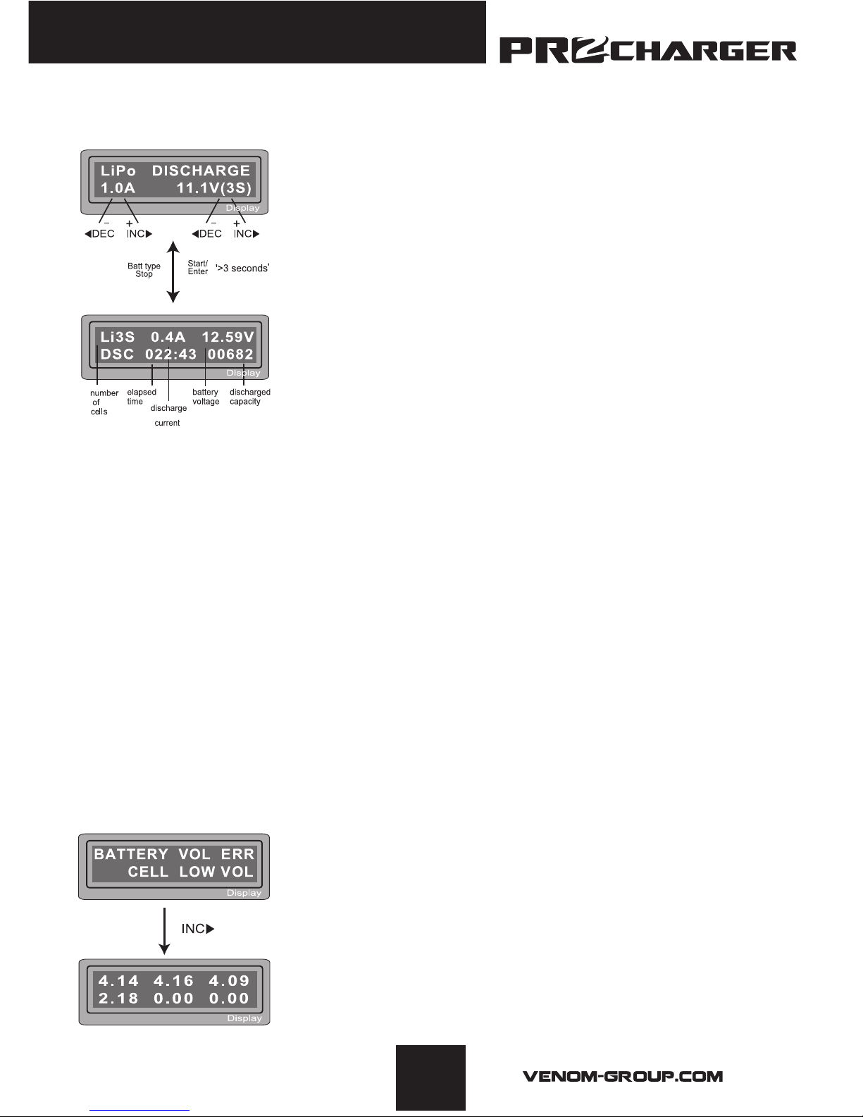
6.4 DISCHARGING A LITHIUM BATTERY
Use this setting to discharge a Lithium pack. The charge
current and pack voltage are adjustable using the methods
shown previously in the charge and balance instructions. Never
exceed 1C for the discharge rate and never use a final voltage
lower than what is recommended by the battery manufacturer.
The balance plug of the battery must be plugged into the
charger for a proper discharge to take place. Press and hold the
START/ENTER button to conrm cell count, then hold the button
again a second time to start the discharge process.
When discharging, the screen provides useful information like
the discharge rate, number of cells being discharged, battery
voltage and the amount of mAh, or capacity that the charger
has removed from the pack being currently discharged. Press Batt type/Stop to stop the
discharging process at any time.
6.5
VOLTAGE BALANCING AND MONITORING DURING THE DISCHARGE
The processor monitors the voltage of individual cells during ‘storage-mode’ and
‘discharge’ of a Lithium battery pack. It tries to regulate the voltages to be equal. For this
feature, the balance plug of the battery pack must be connected to the balance board of
the charger. If the voltage of any one or more cells varies abnormally during the procedure,
It terminates the process with an error message. If this happens, the battery pack contains
a bad cell, or there is a bad connection at the balance plug. You can easily know which
one cell is bad by pressing increase button with the error message on screen to show you
the individual cell voltages. This method of viewing cell voltages can be used during any
lithium battery charge or discharge process provided the balance lead from the battery is
plugged into the charger.
In this example, the charger found that the voltage of one of the
cells in this 4S pack is too low.
By pressing the “increase” button when the error message is
displayed, we can see that cell #4 is reading 2.18, which is below
the minimum recommended 3.0 per cell. If all cells read 0.00, the
balance lead from the battery may have come disconnected.
Also check your balance board connection at the charger.
Page 16
13
667
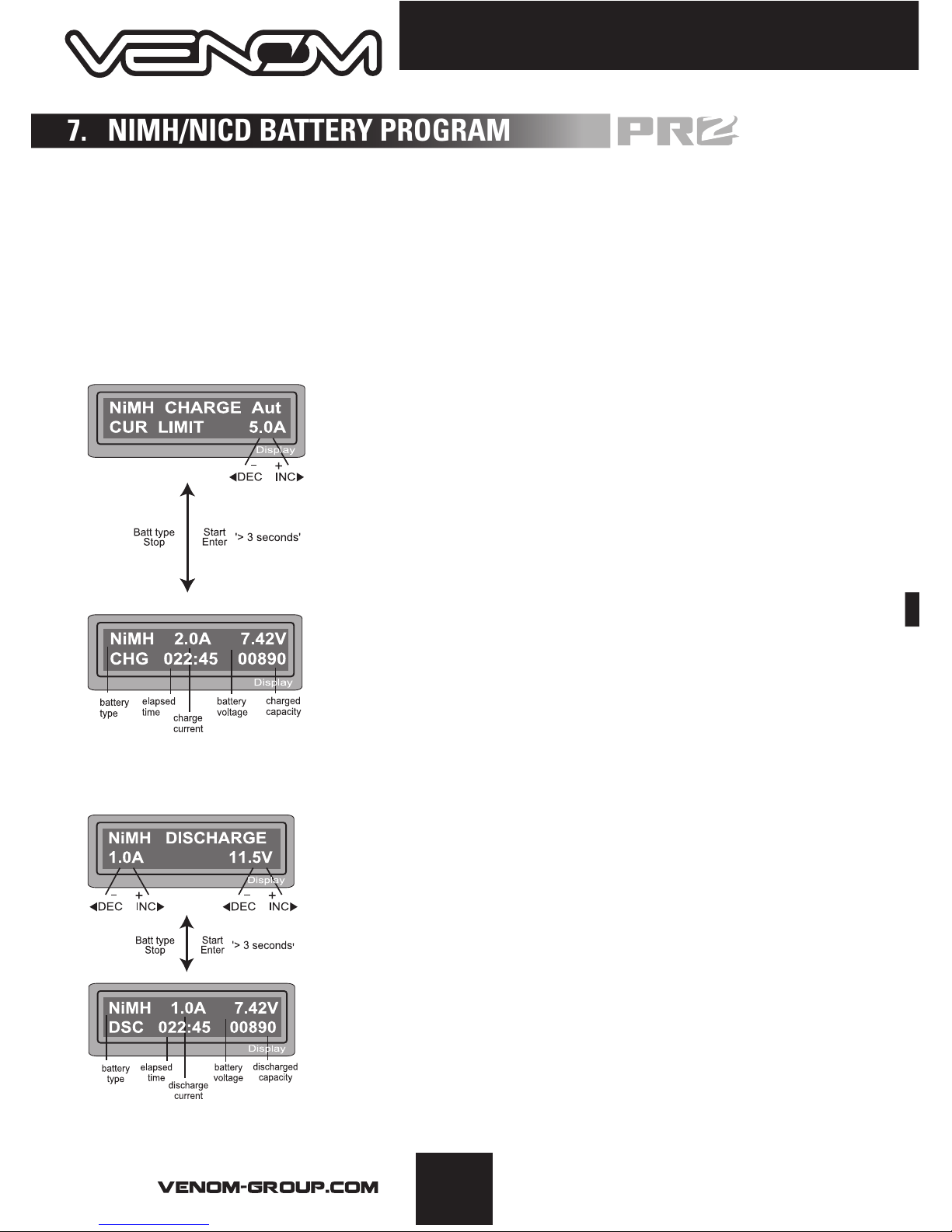
Use these programs only when charging a NiMH (Nickel-Metal-Hydride)or NiCd
(Nickel-Cadmium) battery. To alter the value on the display, press the START/ENTER
key. The charge current can now be altered by using the increase/decrease buttons.
The value will be saved by pressing Start/Enter key once. To start the process, press
and hold the START/ENTER button for more than 3 seconds.
7.1 CHARGING NICD/NIMH BATTERIES
With NiMH and NiCD packs, you do not have to indicate to
the charger how many cells are in the pack. In auto “AUT”
mode, simply set your charge current (no more than a 1C
rating.), press START/ENTER for 3 seconds and the charge
process will begin. In manual “MAN” mode, it will charge
the battery with the charge current you set at the display.
Each mode can be switched by pressing increase/decrease
button simultaneously when the current eld is blinking.
The screen will display the current state of charging. To
stop the process, press the Batt type/Stop key once. An
audible sound will indicate you have ended of process.
7.2 DISCHARGING NICD/NIMH BATTERIES
Set discharge current on the left and final voltage on the
right. The discharge current ranges from 0.1 to 1.0A and the
nal voltage ranges from 0.1 to 25.0V). Refer to your battery’s
specifications to determine optimal discharge current and
nal voltage. To start the process, press START/ENTER key
for more than 3 seconds.
The screen will display the current state of discharge. You
can alter the discharge current by pressing START/ENTER
key during the process. Once you change the current value,
store it by pressing START/ENTER button again. To stop
discharging press Batt type/Stop key once. An audible sound
will indicate the process has ended.
7. NIMH/NICD BATTERY PROGRAM
Page 17
14
© Venom Group International 2013
7.3 CHARGE/DISCHARGE DISCHARGE/CHARGE CYCLE OF
NIMH/NICD BATTERIES
Select the sequence based on the current state of the battery.
If the battery is fully charged, use the Discharge/Charge
sequence. If the battery needs to be charged, use Charge/
Discharge. Press START/ENTER to conrm the setting, then
choose how many times to cycle the battery (1-5). Press and
hold START/ENTER to begin the process.
To stop the process, press the Batt/Stop button once. Change
the discharge or charge current by pressing START/ENTER
while charging. An audible sound will indicate when the process
has ended.
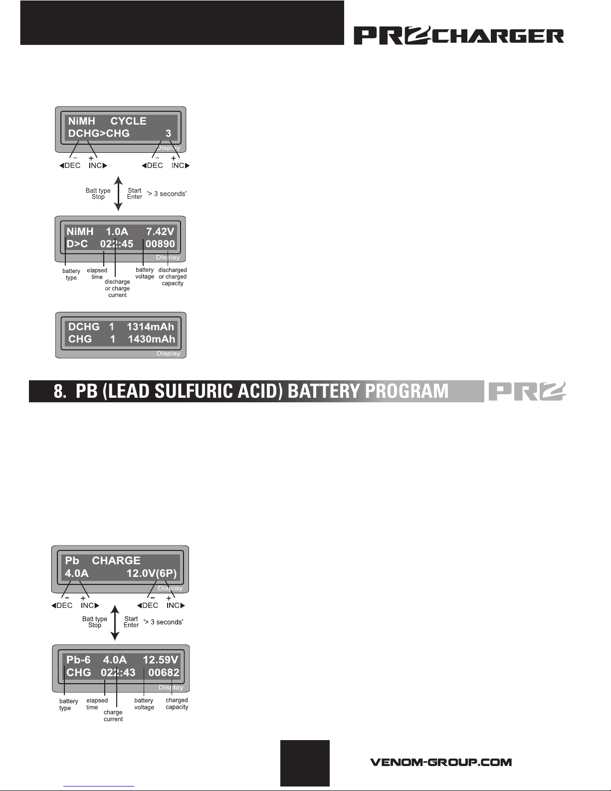
When the process is completed, use the increase/decrease
buttons to see the amount of capacity that was charged/
discharged. By pressing increase/decrease again, the results of
the next charge cycle will be shown.
This program is for charging Pb (lead-sulfuric acid) batteries with a nominal voltage from 2V
to 20V. The optimal charge rate for a Pb battery is 1/10 of the capacity. Pb batteries must NOT
be charged rapidly. Always follow the instructions supplied by the battery manufacturer.
When condent you have the correct settings for your Pb battery, press START/ENTER to
begin editing the settings. Use the increase/decrease buttons to adjust the value and press
START/ENTER to save the selected value.
8.1 CHARGING PB BATTERIES
Set up the charge current on the left and the nominal voltage of
the battery on the right. The charge current ranges from 0.1A to
6.0A and the voltage should be matched with the battery being
charged. Start the charge process by pressing the START/
ENTER button for more than 3 seconds.
The screen will display the current state of charging. To stop the
process, press the Batt type/Stop key once. An audible sound
will indicate you have ended of process.
8. PB (LEAD SULFURIC ACID) BATTERY PROGRAM
Page 18
15
667
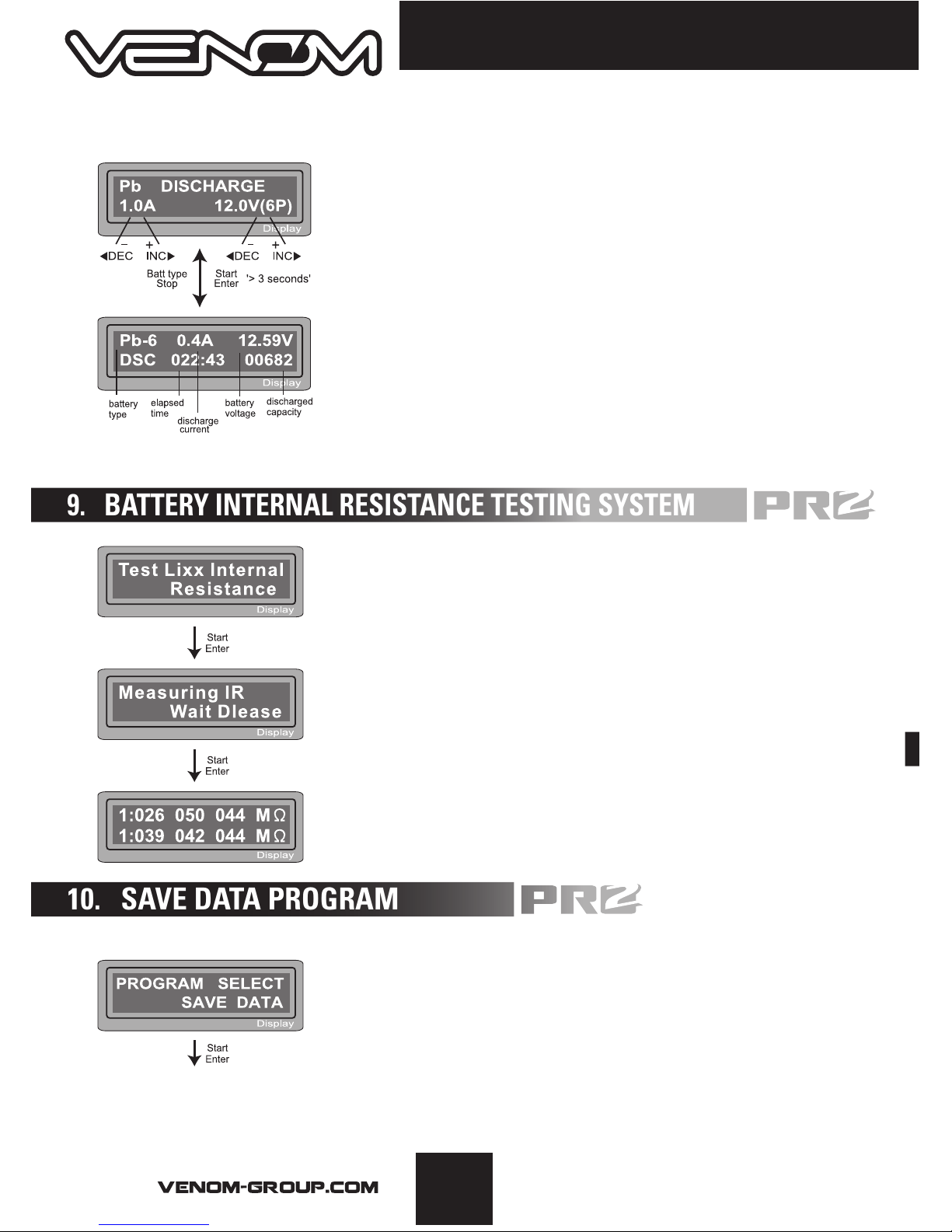
8.2 DISCHARGING A PB BATTERY
Set discharge current on the left and final voltage on the right.
The discharge current ranges from 0.1A to 1.0A.
Start the discharge process by pressing the START/ENTER
button for more than 3 seconds.
The screen will display the current state of discharge. Alter
the discharge current by pressing the START/ENTER button
during charging. Once you have changed the value, save it by
pressing START/ENTER again. To stop the process, press the
Batt type/Stop key once. An audible sound will indicate you
have ended of process.
Internal resistance testing can be a very valuable tool for
battery diagnostics. The data collected from this form of
testing is only truly valuable if the internal resistance is
monitored over the life of a pack. To properly test internal
resistance, you must connect
both the charge lead and the balance lead to the charger.
To begin, press START/ENTER. The charger will provide the
results in the form of a milli-ohm rating. Press increase to
check the total results of the pack. Press increase again to
view the single cell data.
The Venom Pro2 Charger provides a data storage and
load feature for your convenience. This feature can store
information for up to 5 batteries to be called back for the
process of charging or discharging without having to
reprogram the charger. To alter the values, press START/
ENTER, then change the blinking value using the increase/
decrease buttons.
9. BATTERY INTERNAL RESISTANCE TESTING SYSTEM
10. SAVE DATA PROGRAM
Page 19
16
© Venom Group International 2013
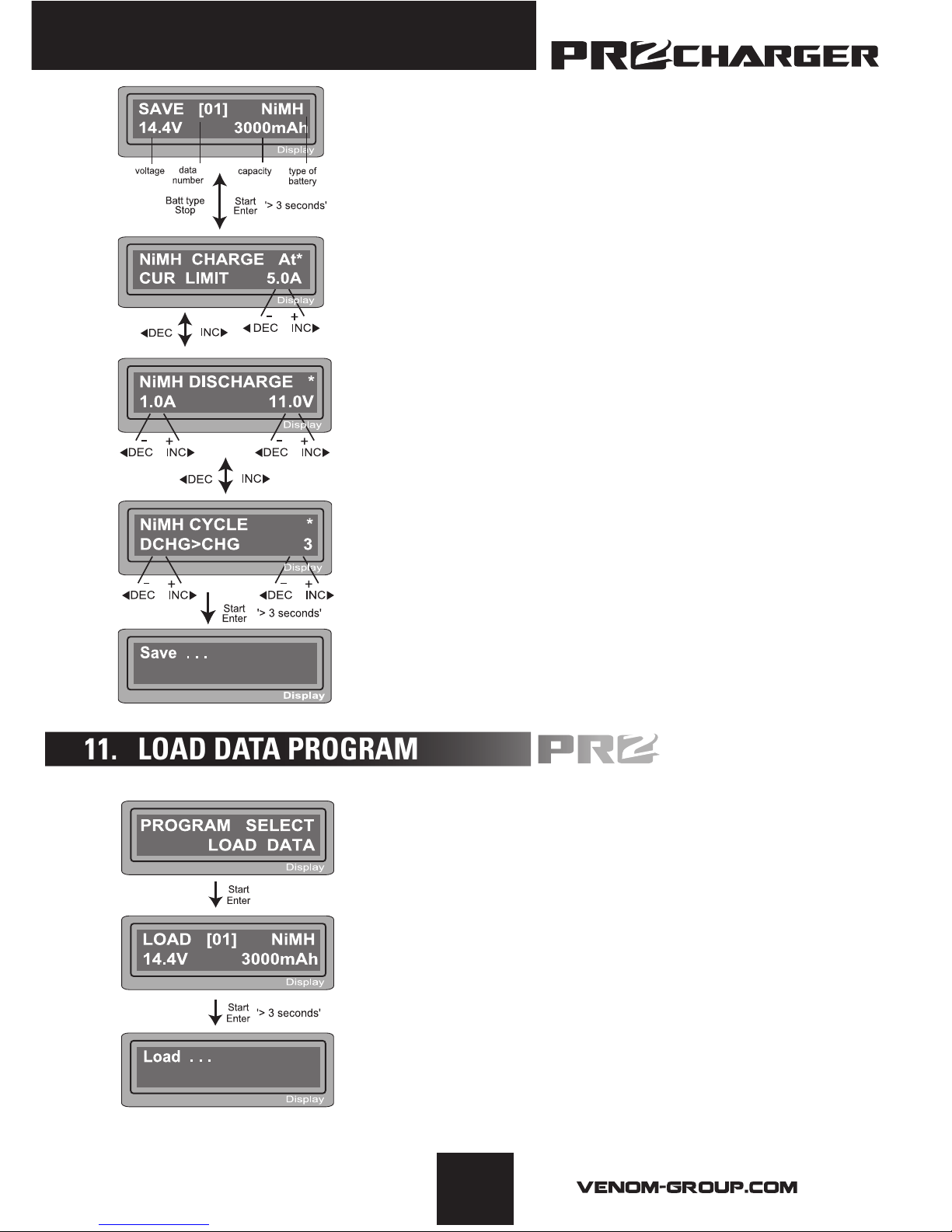
The value settings in this feature do NOT affect the
charge or discharge process, but rather allows you
to store statistics for commonly charged batteries to
speed up the charger setup time. To use this feature,
you will want to change the parameters to the exact
specifications of the batteries you wish to store. This
example shows a 12 cell, NiMH battery with a capacity
of 3000mAh.
Set up the charge current for manual charge mode, or
the current limit for automatic charge mode. Each mode
can be changed by pressing the increase/decrease
buttons at the same time when the “current” field is
blinking.
Setting up discharge current and final voltage.
Setting up the sequence of charge and discharge as
well as the amount of times to cycle.
Saving the data.
This program will call back the data that was stored
during the “Save Data” program. To load the data, press
START/ENTER once. Change the data number to the
battery you wish to recall using the increase/decrease
buttons, then press START/ENTER for 3 seconds.
Program select
Select the data number you wish to load. The data
displayed on screen is matched with the number
selected.
Loading the data.
11. LOAD DATA PROGRAM
Page 20
17
667
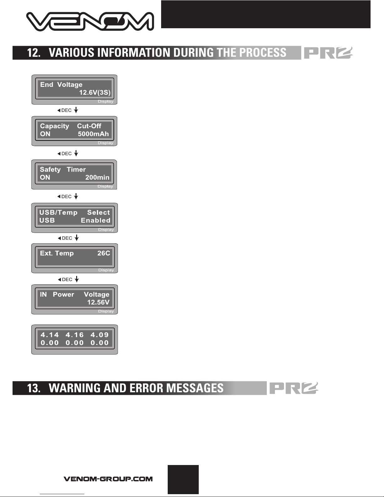
Final voltage was reached when the program ended.
Displayed capacity cut-off function is turned on and the
current value the capacity is set to.
Displayed safety timer is turned on and the duration is set,
in minutes.
Displayed temperature cut-off function is turned on.
The external temperature is displayed when the temp probe
is used.
Present input voltage.
The battery is connected using the balance lead and the
voltages of the three individual cells is being displayed. The
program will display the individual voltage of up to 6 cells.
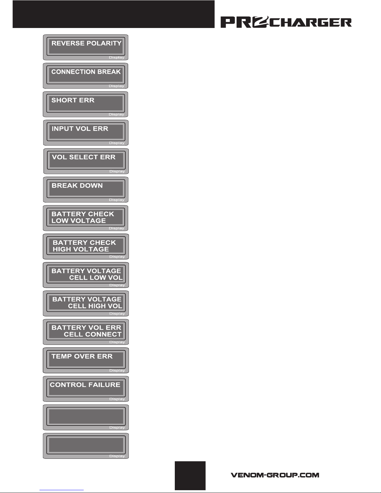
Here is a list of all warning and error messages the charger may display.
Please refer to this list should you have any difficulty charging.
12. VARIOUS INFORMATION DURING THE PROCESS
13. WARNING AND ERROR MESSAGES
Page 21
18
© Venom Group International 2013
Incorrect polarity detected.
Battery connection was interrupted.
Short-circuit of the output termination
Input voltage wrong.
The charger has an internal error. Please contact Venom
customer service.
The voltage is lower than the setting currently selected.
Please check the number of cells in the battery pack.
Voltage in one cell in the pack is too low to charge safely.
Please check the voltages of each cell.
Voltage in one cell in the pack is too high to charge safely.
Please check the voltages of each cell.
Connector error. Please check the connections at the
battery and charger.
Internal temperature of the charger is too high. Allow time
for the charger to cool.
The processor cannot control the feeding current.
Contact Venom customer service.
The battery balance connector or charge leads are not
connected properly for IR testing. Please check your
connections and try again.
The battery balance port or the power line to connect is
incorrect.
Battery Pack IR
0m Ω
1 : --- --- --- mΩ
4 : --- --- --- mΩ
Page 22

19
667
Venom™ warrants this product to be free of material and workmanship defects when
new. Venom™ will at its sole discretion repair or replace defective components free
of charge within 90 days from date of purchase or within 30 days for all electronic
components. This warranty does not cover wear and tear, crash damage, modications,
failure to perform routine maintenance, or any damages arising as a result of improper
use. All warranty claims are to be directed to www.venom-group.com/Customer-Service
Important Notice
Venom™ assumes sole responsibility for our products; therefore, dealers should not
be involved in any warranty issues. All warranty claims are to be directed to Venom™
Customer Service. Before returning any defective product, please contact Venom™ at
www.venom-group.com/Customer-Service
RELEASE OF LIABILITY
Venom™, It’s afliates, manufacturers, distributors, or retail partners shall not be held
liable for any accident, injury to persons, or damage to property resulting from use,
misuse, or abuse of any Venom™ product. In purchasing a Venom™ product the user
agrees to accept responsibility for all such risks.
15. WARRANTY AND SERVICE
14. SPECIFICATIONS
Dual input power(AC/DC): Input AC:100~240Volt
Input DC: 11~18Volt
Circuit power: max.50W for charging
max.5W for discharging
Charge current range: 0.1~6.0A
Discharge current range: 0.1~1.0A
Current drain for balancing LiPO: 300mAh/cell
NiCd/ NiMH battery cell count: 1~15cells
Lithium battery cell count: 1~6Series
Pb battery voltage: 2 to 20V
Weight: 400g
Dimension: 136×127×56mm
Page 23

20
© Venom Group International 2013
GUARANTEE
All products are inspected and adjusted individually before leaving the manufacturer and
are guaranteed to be free of material defects and manufacturing faults.
Notice of Rights
All rights reserved. No part of this manual may be reproduced or transmitted in any form
by any means, electronic, mechanical, photocopying, recording, or otherwise, without the
prior written permission of Venom™. For information on getting permission for reprints
and excerpts, contact customerservice@venom-group.com.
Notice of Liability
The information in this manual is distributed on an “As Is” basis, without warranty. While
every precaution has been taken in the preparation of the manual, Venom™ does not
have any liability to any person or entity with respect to any loss or damage caused or
alleged to be caused directly or indirectly by the information contained in this manual or
by the products described in it.
Charging and discharging batteries has the potential for serious injury to persons and
damage to property. In purchasing this product, the user agrees to accept responsibility
for all such risks, and will not hold Venom™, it’s afliates, manufacturers, distributors,
or retail partners responsible for any accident, injury to persons, or damage to property
resulting from the use of this product.
This appliance is not intended for use by persons (including children) with reduced
physical, sensory or mental capabilities, or lack of experience and knowledge, unless
they have been given supervision or instruction concerning use of the appliance by a
person responsible for their safety.
This product may contain sharp edges or objects that can cause cuts or other bodily
injury. To prevent cuts or other bodily injury, do not contact sharp edges or objects.
This product contains chemicals known to the State of California to cause Cancer, Birth
Defects and other Reproductive Harm. Be responsible, dispose of properly.
Actual product may vary from product shown.
Page 24

VENOM GROUP INTERNATIONAL
14028 N. Ohio Street
Rathdrum, Idaho 83858 USA
AUSTRALIA
PO Box 7325
Alexandria, NSW 2015
CUSTOMER SERVICE
For Customer Service issues
and the quickest warranty service
please visit www.venom-group.com
/venomgroup /Venom_RC
/venomgroupintl
/venomgroup
677
 Loading...