

Venmar AVS HRV EKO 1.5, ERV EKO 1.5, CONSTRUCTO 1.5V, NOVOFIT 1.0 User Manual
HEAT RECOVERY VENTILATORS MODELS
AVS HRV EKO 1.5, AVS CONSTRUCTO 1.5V,
N
OVOFIT 1.0 AND ENERGY RECOVERY
VENTILATOR MODEL AVS ERV EKO 1.5
VB0122 VB0123
VB0126
PLEASE READ AND SAVE THESE INSTRUCTIONS
Venmar Ventilation inc., 550 Lemire Blvd., Drummondville, QC, Canada J2C 7W9
www.venmar.ca
These products earned the
ENERGY STAR®by meeting strict
energy efficiency guidelines set by
Natural Resources Canada and the
US EPA. They meet ENERGY STAR
requirements only when used in
Canada.
08445 rev. C
VB0136
User Guide
2
Congratulations!
You have made an excellent choice! The operating principle of your Heat
Recovery Ventilator or your Energy Recovery Ventilator will give you personal
comfort you have never known before.
We have prepared this User Guide especially for you. Please read it carefully
to ensure you obtain full benefit from your unit. Over the coming months, you will
increasingly appreciate the feeling of living in a more comfortable house.
Please take note that this manual uses the following symbols to emphasize
particular information:
NOTE: Indicates supplementary information needed to fully complete an instruction.
We welcome any suggestions you may have concerning this guide and/or the unit,
and we would appreciate hearing your comments on ways to better serve you.
Please forward all correspondence to us at the address indicated on the product
registration card included with this guide.
WARNING
Identifies an instruction which, if not followed, might cause serious
personal injuries including possibility of death.
!
CAUTION
Denotes an instruction which, if not followed, may severely damage the unit
and/or its components.
CAUTION
Make sure at all times that the outside intake and exhaust hoods are free
from any snow during the winter season. It is important to check your unit
during a big snow storm, so it doesn’t draw in any snow. If this is the case,
please operate the unit in the recirculation mode, or turn it OFF for a few
hours.
Do not use your unit during construction or renovation of your house or
when sanding drywall. This type of dust may damage your system.
Since the electronic control system of the unit is incorporated with a
microprocessor, it may not operate correctly because of external noise or very
short power failure. If this happens, unplug the unit and wait approximately
10 seconds. Then, plug the unit in again.

3
1. DEFROSTING MODE . . . . . . . . . . . . . . . . . . . . . . . . . . . . . . . . . .4
2. C
ONTROLS . . . . . . . . . . . . . . . . . . . . . . . . . . . . . . . . . . . . .4-13
2.1 BOOTING SEQUENCE . . . . . . . . . . . . . . . . . . . . . . . . . . . . . . . . . . .4
2.2 I
NTEGRATED CONTROL . . . . . . . . . . . . . . . . . . . . . . . . . . . . . . . . .5
2.3 ALTITUDE MAIN CONTROL . . . . . . . . . . . . . . . . . . . . . . . . . . . . . .6-9
2.4 LITE-TOUCH CONSTRUCTO MAIN CONTROL . . . . . . . . . . . . . . . . . .10
2.5 CONSTRUCTO MAIN CONTROL . . . . . . . . . . . . . . . . . . . . . . . . . . .11
2.6 O
PTIONAL AUXILIARY CONTROLS . . . . . . . . . . . . . . . . . . . . . .12-13
2.6.1 20/40/60-minute Push-Button Timer . . . . . . . . . . . . . . . . . . . .12
2.6.2 20-minute Light Push Button . . . . . . . . . . . . . . . . . . . . . . . . . .12
2.6.3 Dehumidistat . . . . . . . . . . . . . . . . . . . . . . . . . . . . . . . . . . . . . .13
2.6.4 60-minute Crank Timer . . . . . . . . . . . . . . . . . . . . . . . . . . . . . .13
3. MAINTENANCE . . . . . . . . . . . . . . . . . . . . . . . . . . . . . . . . . .14-15
3.1 SEMI-ANNUAL MAINTENANCE . . . . . . . . . . . . . . . . . . . . . . . . .14-15
3.2 ANNUAL MAINTENANCE . . . . . . . . . . . . . . . . . . . . . . . . . . . . . . . .15
4. TROUBLESHOOTING . . . . . . . . . . . . . . . . . . . . . . . . . . . . . . . .16
Table of Contents

When the outside temperature is below -5°C (23°F), recovery of heat in HRV units
creates frost in the core. For ERV units, when the outside temperature is below
-10°C (14°F), recovery of energy creates frost in the core.
To maintain its proper operation, the unit is programmed to defrost the recovery
core. The defrost frequency varies according to the outside temperature.
During the defrost cycle, the unit shifts to maximum speed and the dampers close.
After defrosting, the unit returns to the operating mode selected by the user.
4
2.1 Booting Sequence
1.
Defrosting Mode
2.
Controls
BOOTING SEQUENCE (CONSTRUCTO 1.5V AND NOVOFIT 1.0 ONLY)
The unit booting sequence is similar to a personal computer booting sequence.
Each time the unit is plugged after being unplugged, or after a power failure, the
unit will perform a 30-second booting sequence before starting to operate. During
the booting sequence, the integrated control LED will light GREEN (unit set in
normal defrost) or AMBER (unit set in extended defrost) for 5 seconds, and then
will shut off for 2 seconds. After that, the LED will light RED for the rest of the
booting sequence. During this RED light phase, the unit is checking and resetting
the motorized damper position. Once the motorized damper position completely
set, the RED light turns off and the booting sequence is done.
NOTE: No command will be taken until the unit is fully booted.
BOOTING SEQUENCE (HRV EKO 1.5 AND ERV EKO 1.5 ONLY)
The unit booting sequence is similar to a personal computer booting sequence.
Each time the unit is plugged after being unplugged, or after a power failure, the
unit will perform a 30-second booting sequence before starting to operate. During the
booting sequence, the integrated control LED will light AMBER for 10 seconds.
After that, the LED will light RED for the rest of the booting sequence. During this
RED light phase, the unit is checking and resetting the motorized damper
position. Once the motorized damper position completely set, the RED light turns
off and the booting sequence is done.
NOTE: No command will be taken until the unit is fully booted.
5
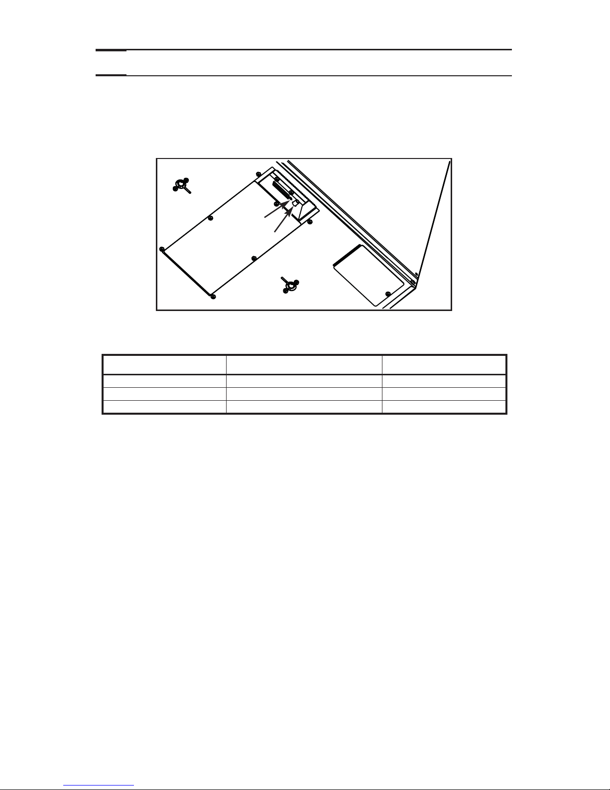
2.2 Integrated Control
2.
Controls (cont’d)
All units are equipped with an integrated control, located under the unit, on the
recessed side of electrical compartment. Plug the unit. Use the push button (1) to
control the unit. The LED (2) will then show on which mode the unit is in.
Refer to table below to see how to operate the unit using its integrated control.
If a problem occurs during the unit operation, its integrated control LED (2) will
blink. The color of the blinking light depends on the type of error detected. Refer to
Section 4 Troubleshooting
on last page for further details.
NOTE: When using main control, the integrated control must be turned off.
PRESS ON PUSH BUTTON LED COLOR RESULTS
ONCE AMBER UNIT IS ON LOW SPEED
TWICE GREEN UNIT IS ON HIGH SPEED
THREE TIMES NO LIGHT UNIT IS OFF
VD0207
1
2
BOTTOM OF THE UNIT
 Loading...