

Venmar VCS500 SERIES, VCS550 SERIES Installation Instructions Manual
HB0181
INSTALLATION INSTRUCTIONS
VCS500 AND VCS550 SERIES
! !
INTENDED FOR DOMESTIC COOKING ONLY
READ AND SAVE THESE INSTRUCTIONS
INSTALLER: LEAVE THIS MANUAL WITH HOMEOWNER.
HOMEOWNER: USE AND CARE INFORMATION ON PAGE 11.
Venmar Ventilation ULC, 550 Lemire Blvd., Drummondville QC J2C 7W9 1-800-567-3855
REGISTER YOUR PRODUCT ONLINE AT: www.bnv.ca
For additional information - visit www.venmar.ca
22745 rev. 04

!
WARNING
!
WARNING
TO REDUCE THE RISK OF FIRE, ELECTRIC SHOCK OR
INJURY TO PERSONS, OBSERVE THE FOLLOWING:
1. Use this unit only in the manner intended by the manufacturer.
If you have questions, contact the manufacturer at the address
or telephone number listed in the warranty.
2. Before servicing or cleaning unit, switch power off at service
panel and lock service disconnecting means to prevent
power from being switched on accidentally. When the service
disconnecting means cannot be locked, securely fasten a
prominent warning device, such as a tag, to the service panel.
3. Installation work and electrical wiring must be done by
qualified personnel in accordance with all applicable codes
and standards, including fire-rated construction codes and
standards.
4. Sufficient air is needed for proper combustion and exhausting
of gases through the flue (chimney) of fuel burning equipment
to prevent backdrafting. Follow the heating equipment
manufacturer’s guidelines and safety standards such as
those published by the National Fire Protection Association
(NFPA) and the American Society for Heating, Refrigeration
and Air Conditioning Engineers (ASHRAE) and the local code
authorities.
5. When cutting or drilling into wall or ceiling, do not damage
electrical wiring and other hidden utilities.
6. Ducted fans must always be vented outdoors.
7. Do not use this unit with any solid-state speed control device.
8. To reduce the risk of fire, use only metal ductwork.
9. This unit must be grounded.
10. When applicable, local regulations comprise more
restrictive installation and/or certification requirements,
the aforementioned requirements prevail on those of this
document and the installer agrees to conform to these at his
own expense.
TO REDUCE THE RISK OF A RANGE TOP GREASE FIRE:
a) Never leave surface units unattended at high settings. Boilovers
cause smoking and greasy spillovers that may ignite. Heat oils
slowly on low or medium settings.
b) Always turn power hood ON when cooking at high heat or
when flambeing food (i.e.: Crêpes Suzette, Cherries Jubilee,
Peppercorn Beef Flambé).
c) Clean ventilating fans frequently. Grease should not be allowed
to accumulate on fan, filters or in exhaust ducts.
d) Use proper pan size. Always use cookware appropriate for the
size of the surface element.
TO REDUCE THE RISK OF INJURY TO PERSONS IN THE
EVENT OF A RANGE TOP GREASE FIRE, OBSERVE
THE FOLLOWING*:
1. SMOTHER FLAMES with a close-fitting lid, cookie sheet or
metal tray, then turn off the burner. BE CAREFUL TO PREVENT
BURNS. IF THE FLAMES DO NOT GO OUT IMMEDIATELY,
EVACUATE AND CALL THE FIRE DEPARTMENT.
2. NEVER PICK UP A FLAMING PAN — You may be burned.
3. DO NOT USE WATER, including wet dishcloths or towels —
This could cause a violent steam explosion.
4. Use an extinguisher ONLY if:
A. You own a Class ABC extinguisher and you know how to
operate it.
B. The fire is small and contained in the area where it started.
C. The fire department has been called.
D. You can fight the fire with your back to an exit.
* Based on “Kitchen Fire Safety Tips” published by NFPA.
CAUTION
1. For indoor use only.
2. For general ventilating use only. Do not use to exhaust
hazardous or explosive materials and vapors.
3. To avoid motor bearing damage and noisy and/or unbalanced
impellers, keep drywall spray, construction dust, etc. off power
unit.
4. Your hood motor has a thermal overload which will automatically
shut off the motor if it overheats. The motor will restart when it
cools down. If the motor continues to shut off and restart, have
the hood serviced.
5. The minimum hood distance above cooktop must not be
less than 24” (30” over a gas range). A maximum of 30”
above cooktop is recommended for best capture of cooking
impurities.
6. Two installers are recommended because of the large size and
weight of this unit.
7. To reduce the risk of fire and to properly exhaust air, be sure to
duct air outside — Do not exhaust air into spaces within walls
or ceiling or into attics, crawl space or garage.
8. Because of the high exhausting capacity of this hood, you
should make sure enough air is entering the house. Open a
window close to or in the kitchen.
9. To reduce the risk of fire and electrical shock, the Venmar Chef
VCS500 and VCS550 Series models should only be installed
with their own built-in blowers.
10. Please read specification label on product for further
information and requirements.
2
1. PREPARE THE INSTALLATION
!
WARNING
When performing installation, servicing or cleaning the unit, it is recommended to wear safety glasses and gloves.
NOTE: Before proceeding to the installation, check the contents of the box. If items are missing or damaged, contact the manufacturer.
Make sure that the following items are included:
- Hood
- Accessories • Decorative flue assembly (lower and upper flues)
• Hood mounting bracket
• Upper flue mounting bracket
• 2 micromesh filters (for model VCS500)
• 2 hybrid filters (for model VCS550)
• 6” round adapter/damper (for vertical discharge), in a bag
• 3¼” x 10” adapter/damper (for horizontal or vertical discharge)
• Suction cup (taped to one of the GU10 halogen bulbs) (for model VCS500)
• Bag of parts including: 5 no. 8 x 1½” countersunk screws, 8 no. 8 x 3/4” screws, 6 no. 8 x 3/8” screws,
6 drywall anchors, 3 washers, 2 no. 8 x 1/2”, 2 neoprene pieces. If need be,
discard extra hardware.
Parts sold separately:
- Duct, elbows, wall or roof caps.
- Optional flue extensions for 10-ft. ceilings models no. 63680 (Stainless steel) or 63685 (Black stainless steel).
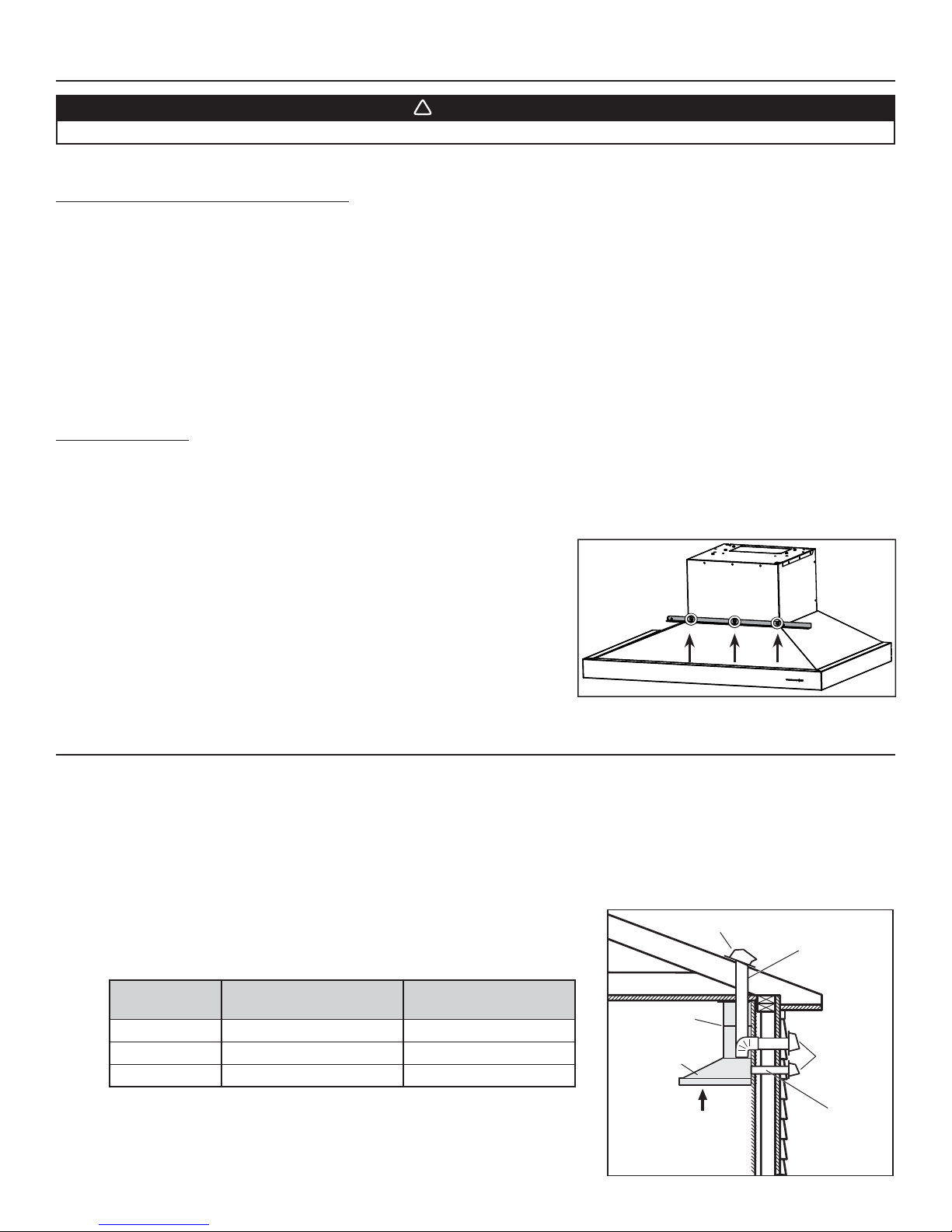
Before installation, remove and discard the shipping bracket (in grey) and its retaining
SCREW LOCATIONS
screws. See illustration on the right.
HD0816
2. SELECT INSTALLATION TYPE
NOTE: During the installation, protect countertop and/or cooktop.
Plan where and how the ductwork will be installed.
Install proper-sized ductwork, elbows and roof or wall cap depending on the type of installation. For vertical discharge, use 6” round
or 3¼” x 10” ductwork and for horizontal discharge use 3¼” x 10” ductwork only. Use metal foil duct tape to seal duct joints.
The minimum hood distance above cooktop is 24” (30” over a gas range). A maximum of 30” above cooktop is recommended
for best capture of cooking impurities.
Distances over 30” are at the installer and users discretion providing that ceiling height and decorative flue length allow it.
CEILING HEIGHT
MINIMUM HOOD DISTANCE ABOVE
ELECTRIC RANGE COOKTOP
MINIMUM HOOD DISTANCE
ABOVE GAS RANGE COOKTOP
8 FT. 24 IN. 30 IN.
FT. 28½ IN. 30 IN.
9
FT.* 28½ IN. 30 IN.
10
DECORATIVE
FLUE
HOOD
ROOF CAP
3¼” X 10” DUCT
OR
6 ” ROUND DUCT
WALL
AP
C
* 10-ft. ceilings require flue extension model no. 63680 (Stainless
steel) or 63685 (Black stainless steel) (sold separately).
REFER TO CHART
FOR
DISTANCE ABOVE
COOKING
HH0246A
SURFACE
3¼” X 10” DUCT
3
2. SELECT INSTALLATION TYPE (CONT'D)
12¾”
14
15
/16”
C
L
9¾”
HK0203A
67/16”
1115/16”
1715/16”
24”
WIDTH HOOD
30” WIDTH HOOD
36” WIDTH HOOD
3¼”
HR0122
Refer to illustrations below to locate duct opening according to discharge type chosen (grey parts to be installed later).
VERTICAL DISCHARGE
15/16”
3”
1115/16”
HK0202A
1415/16”
17
VERTICAL DISCHARGE
24”
30” WIDTH HOOD
36” WIDTH HOOD
6” DIA.
15
/16”
WIDTH HOOD
C
L
9¾”
24”
30” WIDTH HOOD
36” WIDTH HOOD
C
L
7
/8”
2
3¼”
WIDTH HOOD
1115/16”
1415/16”
15
/16”
17
HORIZONTAL DISCHARGE
HK0201A
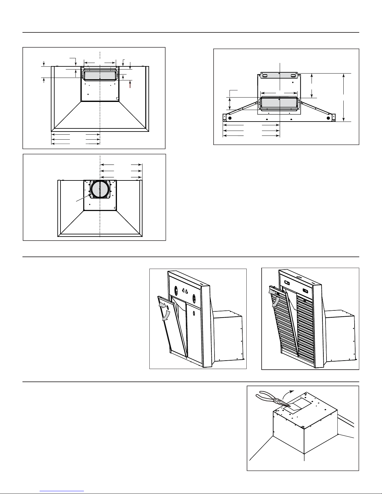
3. REMOVE GREASE FILTERS
VCS500
Rest the range hood on a table. Remove tapes on
filters. Remove filters from range hood by pushing
them down and tilt, then set aside the filters.
Remove both styrofoam pieces and tape from
under the blower and discard.
1
2
HD0811
4. CHOOSE THE OPENING
FOR VERTICAL DISCHARGE:
Remove the knockout in order to clear vertical discharge opening (see illustration beside).
VCS550
1
2
HD0812
4
4. CHOOSE THE OPENING (CONT'D)
FOR HORIZONTAL DISCHARGE:
From outside the unit, remove the knockout from back of hood (see illustration beside).
HR0123
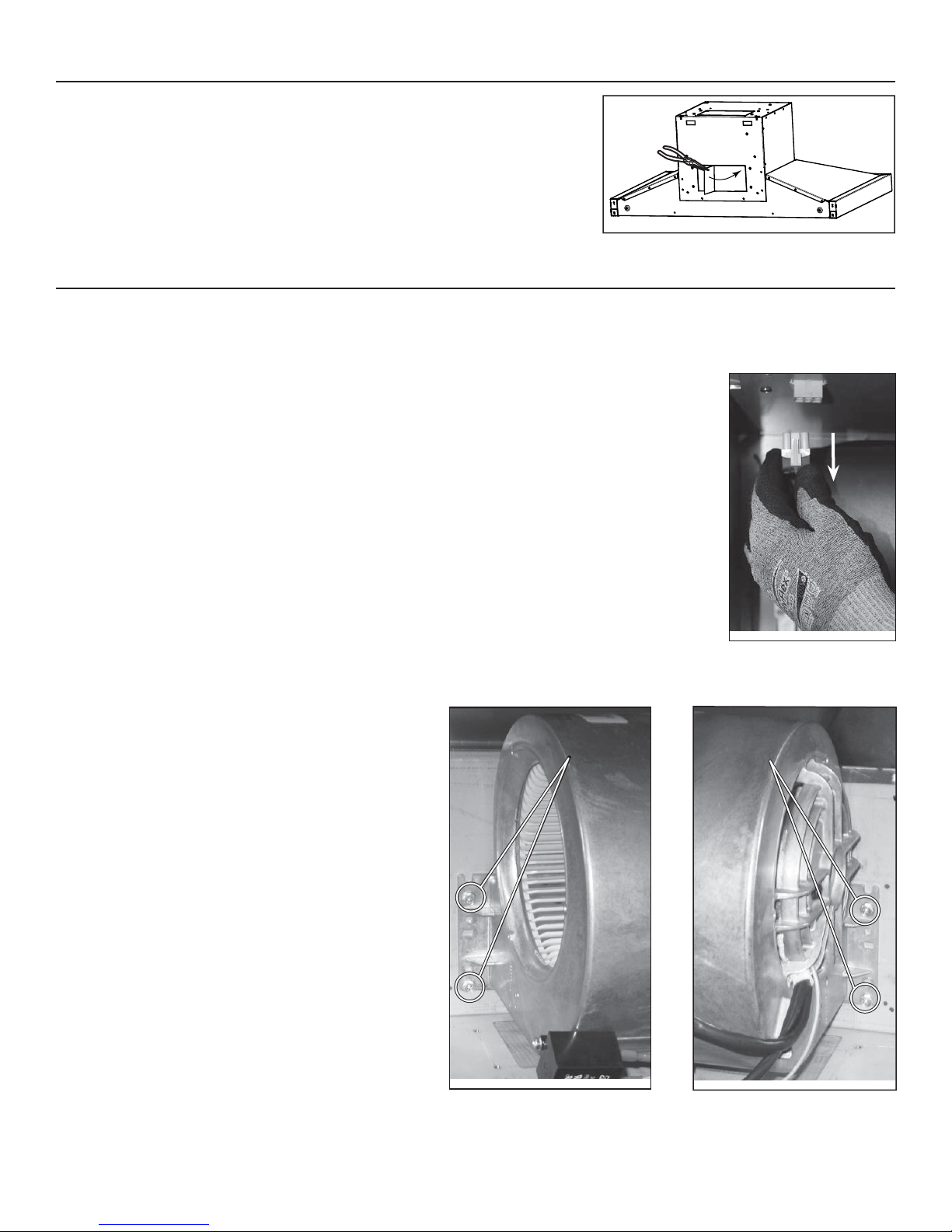
5. BLOWER REMOVAL (HORIZONTAL DISCHARGE ONLY)
The VCS500 and VCS550 Series range hoods are factory shipped with the blower mounted for a vertical discharge configuration. For a
horizontal discharge configuration, disassemble the blower from the inner top of the hood (see procedure below). It will be assembled to the
inner back of the hood once the hood is mounted on the wall.
1) Unplug the blower.
2) Using a 5/16” socket, or a Robertson or a Phillips no. 2
screwdriver, remove the 4 blower mounting screws (2 on each
side) from the inner top of the hood. Set the blower and
screws aside.
HD0385
LEFT SIDE MOUNTING
SCREW LOCATIONS
HD0817
RIGHT SIDE MOUNTING
SCREW LOCATIONS
HD0386
5
 Loading...