

Page 1
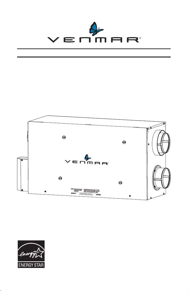
USER GUIDE
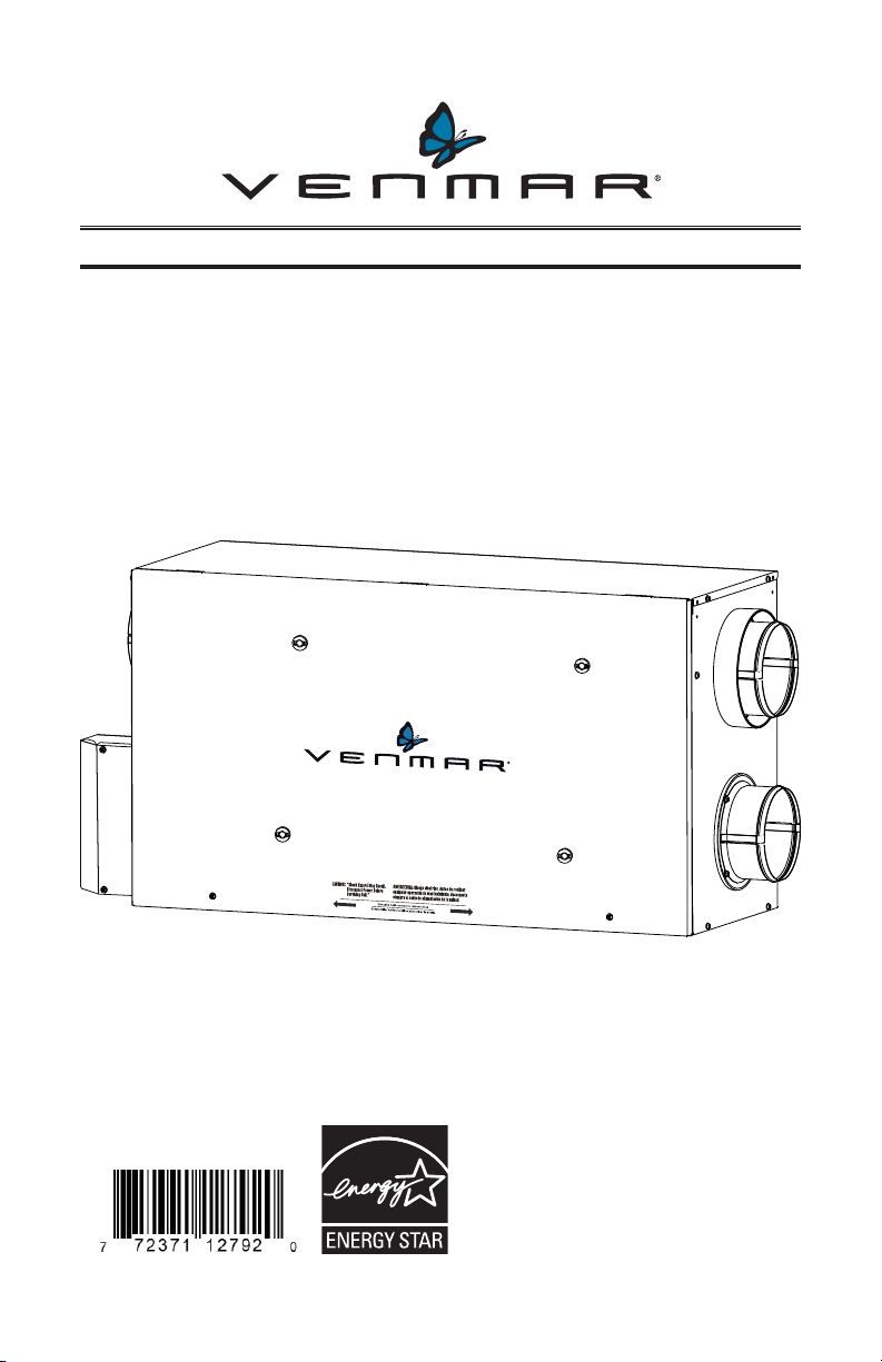
HEAT RECOVERY VENTILATOR
MODEL H50100H
AND
ENERGY RECOVERY VENTILATOR
MODEL H50100E
VB0195
READ AND SAVE THESE INSTRUCTIONS
INSTALLER: LEAVE THIS MANUAL WITH HOMEOWNER
Venmar Ventilation ULC, 550 Lemire Blvd., Drummondville, QC, Canada J2C 7W9
REGISTER YOUR PRODUCT ONLINE AT: www.venmar-usa.com
For additional information - visit www.venmar-usa.com
These products earned the
ENERGY STAR® by meeting strict energy
efficiency guidelines set by Natural
Resources Canada and the US EPA. They
meet ENERGY STAR requirements only
when used in Canada.
21455 rev. 04
Page 2
Congratulations!
You have made an excellent choice! The operating principle of your Heat Recovery Ventilator
or your Energy Recovery Ventilator will give you personal comfort you have never known
before.
We have prepared this User Guide especially for you. Please read it carefully to ensure you
obtain full benefit from your unit. Over the coming months, you will increasingly appreciate the
feeling of living in a more comfortable house.
Please take note that this manual uses the following symbols to emphasize particular
information:
WARNING
!
Identifies an instruction which, if not followed, might cause serious
personal injuries including possibility of death.
CAUTION
Identifies an instruction which, if not followed, may severely damage the
unit and/or its components.
NOTE: Indicates supplementary information needed to fully complete an instruction.
We welcome any suggestions you may have concerning this guide and/or the unit, or ways to
better serve you. Please forward all correspondence at the address below:
Venmar Ventilation ULC
Customer Service
550 Lemire Blvd.
Drummondville, QC J2C 7W9
CAUTION
Make sure at all times that the outside intake and exhaust hoods are free
from any snow during the winter season. It is important to check your unit
during a big snow storm, so it doesn’t draw in any snow. If this is the case,
please operate the unit in recirculation mode, or turn it OFF for a few hours.
Do not use your unit during construction or renovation of your house or
when sanding drywall. This type of dust may damage your system.
Since the electronic control system of the unit is incorporated with a
microprocessor, it may not operate correctly because of external noise
or very short power failure. If this happens, unplug the unit and wait
approximately 10 seconds. Then, plug the unit in again. At least once a
year, the unit mechanical and electronic parts should be inspected by
qualified service personnel.
CAUTION
When leaving the house for a long period of time (more than two weeks), a
responsible person should regularly check if the unit operates adequately.
If the ductwork runs through an unconditioned space (e.g.: attic), the unit
must operate continuously except when performing maintenance and/or
repair. Also, the ambient temperature of the house should never drop
below 65°F (18°C).
2
Page 3
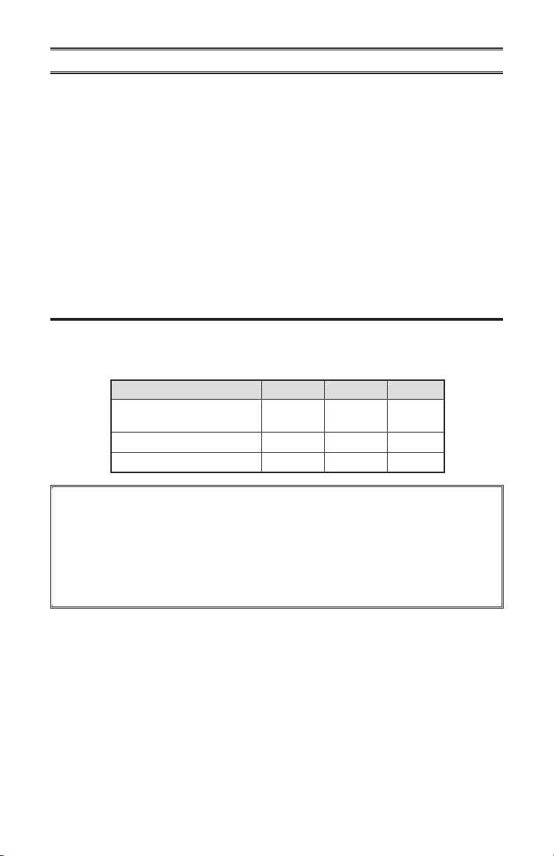
TABLE OF CONTENTS
1. SERVICE PAR TS . . . . . . . . . . . . . . . . . . . . . . . . . . . . . 3
2. CONTROLS. . . . . . . . . . . . . . . . . . . . . . . . . . . . . . . . 4
2.1 BOOTING SEQUENCE . . . . . . . . . . . . . . . . . . . . . . . . . . . . . 4
2.2 OPTIONAL MAIN AND AUXILIARY CONTROLS . . . . . . . . . . . . . . . . . . . 4
3. MAINTENANCE . . . . . . . . . . . . . . . . . . . . . . . . . . . . . 5-7
3.1 QUARTERLY MAINTENANCE. . . . . . . . . . . . . . . . . . . . . . . . . . 5-6
3.2 ANNUAL MAINTENANCE . . . . . . . . . . . . . . . . . . . . . . . . . . . . 7
4. TROUBLESHOOTING . . . . . . . . . . . . . . . . . . . . . . . . . . . . 8
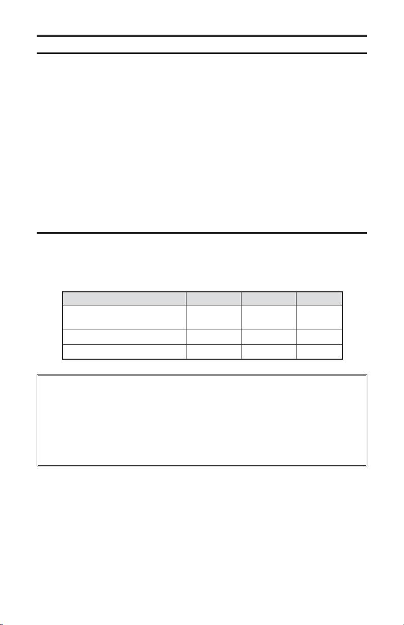
1. SERVICE PARTS
All parts listed in the following table are available where you have bought your unit.
NOTE: Please note that parts not listed are not available; those parts require assembly
knowledge that only manufacturer can garantee.
DESCRIPTION H50100H H50100E QUANTITY
HEPA filter (1 per kit) and
prefilter (2 per kit) kit
Prefilter (2 per kit) 61561 61561
Core filter 61563 61562
21293 21293
1
1
2
REPLACEMENT PARTS AND REPAIRS
In order to ensure your ventilation unit remains in good working condition, you must use
Venmar Ventilation ULC genuine replacement parts only. Venmar Ventilation ULC genuine
replacement parts are specially designed for each unit and are manufactured to comply
with all the applicable certification standards and maintain a high standard of safety. Any
third party replacement part used may cause serious damage and drastically reduce the
performance level of your unit, which will result in premature failing. Venmar Ventilation ULC
recommends to contact a certified service depot for all replacement parts and repairs.
3
Page 4
2. CONTROLS
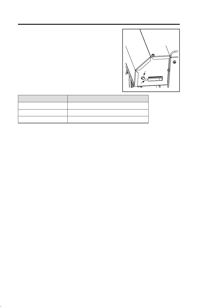
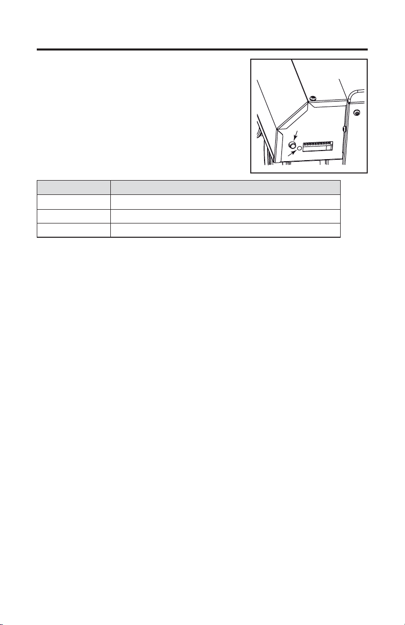
This unit is equipped with an integrated control located
under the electrical compartment of the unit. Use the push
button (1) to control the unit; the LED (2) will then show
which mode the unit is in (see illustration at right and table
below).
1
2
VD0310
LED COLOR RESULTS
AMBER UNIT IS ON LOW SPEED
GREEN UNIT IS ON HIGH SPEED
NO LIGHT UNIT IS OFF OR CONTROLLED BY A MAIN CONTROL
NOTE: The integrated control must be turned OFF to use an optional main control.
If a problem occurs during the unit operation, its integrated control LED (2) will blink. The color
of the blinking light depends on the type of error detected. Refer to Section 4 Troubleshooting
on last page for further details.
2.1 BOOTING SEQUENCE
The unit booting sequence is similar to a personal computer boot sequence. Each time
the unit is plugged after being unplugged, or after a power failure, the unit will perform a
30-second booting sequence before starting to operate.
During the booting sequence, the integrated defrost control LED will light AMBER for
5 seconds, and then will shut off for 2 seconds. After that, the LED will light RED for
the rest of the booting sequence. During this RED light phase, the unit is checking and
resetting the motorized damper position. Once the motorized damper position completely
set, the RED light turns off and the booting sequence is done.
NOTE: No command will be taken until the unit is fully booted.
2.2 OPTIONAL MAIN AND AUXILIARY CONTROLS
For more convenience, this unit can also be controlled using an optional main wall
control. Many models can be used, but only one main wall control can be connected to
the unit.
NOTES: 1. The integrated control must be turned OFF to use an optional main control.
2. If an optional auxiliary control is used, if activated, the operation of this
For more information about the available controls and their operation modes, refer to the
Main and auxiliary wall control User Guide (included with the ventilation unit and also
available at www.venmar-usa.com).
auxiliary control will override the optional main control operation.
4
Page 5
3. MAINTENANCE
WARNING
!
Risk of electric shock. Before performing any maintenance, always turn off
and disconnect the unit from its power source. When cleaning the unit, it
is recommended to wear safety glasses and gloves.
This unit needs quarterly and annual maintenances.
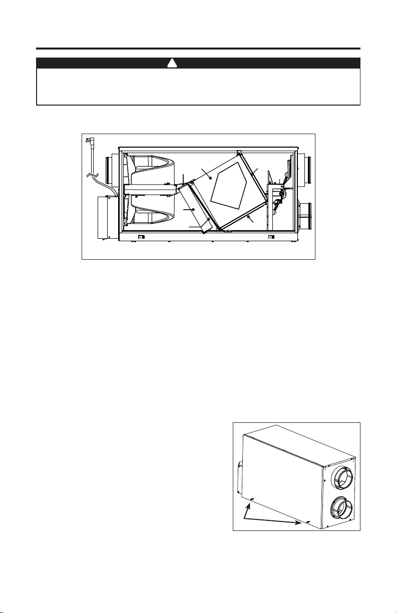
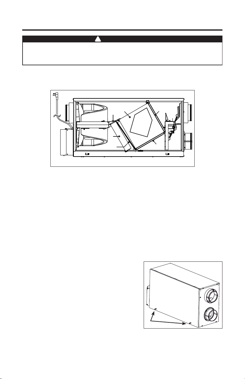
Refer to the illustration below to identify the inner removable parts of your unit:
AB
E
D
VL0060
A. Heat or energy recovery core
B. Heat or energy recovery core filters (2)
C. Prefilter
D. HEPA filter
E. Core bracket
3.1 QUARTERLY MAINTENANCE
Turn the unit OFF and unplug it.
Using a Phillips or a Robertson
screwdriver, loosen both door screws
(A).
NOTE: The screws will stay attached to
the door.
C
B
A
VD0302
5
Page 6
3. MAINTENANCE (CONT’D)
3.1 QUARTERLY MAINTENANCE (CONT’D)
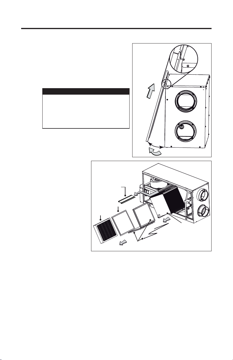
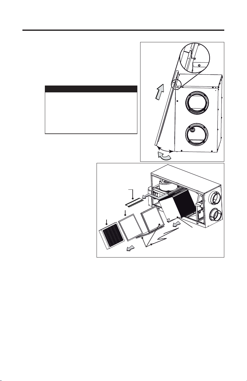
Open (B) and lift out the door (C).
CAUTION
In order to prevent damages to
the door hooks, do not open
completely the unit door; tilt it
about 3" from the unit base and
lift it up. See illustration at right.
CORE BRACKET
Slide out the heat
or energy recovery
core, the core
bracket the bottom
filter retaining wire
and all the filters.
HEPA
F
ILTER
PREFILTER
C
±3”
B
VD0303A
HEAT OR ENERGY
RECOVERY CORE
VL0061
*Bottom filter retaining wire only on H50100E unit.
CORE FILTERS AND BOTTOM
FILTER RETAINING WIRE*
Clean the inside wall of the unit with a damp cloth, then wipe with a dry one.
Remove dust on core using a vacuum cleaner with a soft brush attachment.
Wash both core filters under hot water with mild soap. Rinse thoroughly and let
dry completely.
Reinstall the recovery core with its filters and the retaining wire (if present).
NOTE: The recovery core must be reinstalled BEFORE the core bracket.
Reinstall the HEPA filter but before reinstalling the prefilter, look at the
installation date on HEPA filter frame. If there are more than 6 months
passed, discard the prefilter and install a new one, but keep the HEPA filter.
Reinstall the door, plug back the unit and turn it on.
NOTE: The unit will return to its previous setting after a 30-second delay for
boot sequence.
6
Page 7
3. MAINTENANCE (CONT’D)
3.2 ANNUAL MAINTENANCE
Perform steps to of the regular maintenance then continue with the followings:
EXCLUSIVELY FOR H50100H UNITS
Allow the heat recovery core to soak for 3 hours in a solution of warm water and
mild soap (dishwashing liquid).
Rinse carefully, drain off water and reinstall with its filters.
EXCLUSIVELY FOR H50100E UNITS
Do not soak in water. The energy recovery core can easily be
damaged especially if it is soaked.
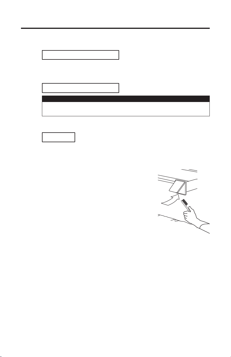
Use a vacuum cleaner with a soft brush attachment to remove dust on core,
then reinstall with its filters.
ALL UNITS
CAUTION
NOTE: The recovery core must be reinstalled BEFORE the core bracket.
Discard HEPA filter and its prefilter and replace with new ones. DO
NOT FORGET TO WRITE THE INSTALLATION DATE ON NEW HEPA
FILTER FRAME.
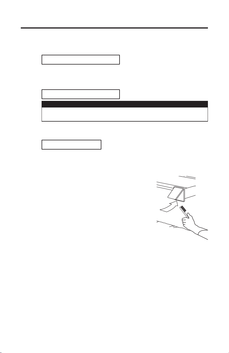
Check the exterior hoods; make sure there are no
leaves, twigs, ice or snow that could be drawn into
the vent. Clean if necessary.
VO0230
Reinstall the door, plug back the unit and turn it on.
NOTE: The unit will return to its previous setting after a 20-second delay for
boot sequence.
7
Page 8
4. TROUBLESHOOTING
WARNING
!
Shock hazard. Never open the electronic box. No user-serviceable parts
inside. There is a fuse on the electronic board. Never attempt to replace it.
Refer servicing to qualified service personnel.
If the unit does not work properly, reset the unit by unplugging it for one minute and
then replug it. If it is still not working properly, refer to table below.
PROBLEMS YOU SHOULD TRY THIS
1 Unit does not work. • See if the unit is plugged in.
2 Condensation on windows
(air too humid).
3 Inside air too dry
(on cold season).
4 Air too cold at the air supply
grille (on cold season).
5 The LED of the integrated
control is blinking GREEN.
6 The LED of the integrated
control is blinking AMBER.
7 The integrated control
push-button does not work.
• Check if the upper left port is free from packaging
material.
• See if the unit is receiving power from the house
circuit breaker or fuse.
• Operate the unit on maximum speed ventilation
until the situation is corrected.
• Leave curtains half-open to allow air circulation.
• Store all firewood in a closed room with a
dehumidifier or in a well ventilated room, or store
the wood outside.
• Do not adjust the thermostat of your heating
system below 64°F (18°C).
• Temporarily use a humidifier.
• Operate the unit in recirculation mode
(if available).
• Check if the exterior hood are not blocked,
specifically the exhaust air to outside one.
• Operate the unit in low speed ventilation or in
intermittent or recirculation mode (if available).
• Reset the unit by unplugging it for 30 seconds.
• If the problem is not solved, there is a problem
with the thermistor. The unit is still working, but
will defrost frequently. Contact your installer.
• Reset the unit by unplugging it for 30 seconds.
• If the problem is not solved, there is a problem
with the damper system. The unit is OFF. For a
5-hour period, the unit will try to reset the damper
system every 30 minutes. After 5 hours, if the
problem is not solved, the unit stops trying to
reset the damper system.
• Contact your installer.
• The 30-second boot sequence is not completed,
see step 2.1 Booting Sequence on page 4.
For optional wall controls problems, refer to the Troubleshooting section in the Main and
auxiliary wall controls user guide (included with the ventilation unit and also available at
www.venmar-usa.com).
If the problem is still not solved, contact your installer or the nearest approved Service Center.
8
Page 9
MANUAL DEL USUARIO
VENTILADOR PARA LA RECUPERACIÓN DEL CALOR
MODELO H50100H
Y
VENTILADOR PARA LA RECUPERACIÓN DE ENERGÍA
MODELO H50100E
VB0195
LEA Y CONSERVE ESTAS INSTRUCCIONES
INSTALADOR: ENTREGUE ESTE MANUAL AL CLIENTE
Venmar Ventilation ULC, 550 Lemire Blvd., Drummondville, QC, Canada J2C 7W9
REGISTRE SU PRODUCTO EN LÍNEA EN: www.venmar-usa.com
Para obtener más información, visitar nuestro sitio www.venmar-usa.com
Estos productos han sido distinguidos con el logotipo ENERGY STAR®
al cumplir las directrices de eficiencia energética establecidas por el
Ministerio de Recursos Naturales de Canadá y la Agencia Federal de
Protección Ambiental (EPA) de Estados Unidos. Los productos cumplen
las exigencias del programa ENERGY STAR únicamente cuando se
emplean en Canadá.
21455 rev. 04
Page 10
¡Felicitaciones!
Ha tomado una excelente decisión. El principio de funcionamiento del ventilador para la
recuperación del calor y del ventilador para la recuperación de energía le brindará un confort
personal desconocido.
Este manual del usuario ha sido preparado especialmente para usted. Léalo atentamente
para sacar el máximo partido del aparato. En los próximos meses agradecerá cada vez más
la sensación de llegar a una casa más confortable.
Con el fin de hacer hincapié en determinada información, en este manual se emplean los
siguientes símbolos:
ADVERTENCIA
!
Se refiere a una instrucción que, de no seguirse, podría causar daños
corporales e incluso la muerte.
PRECAUCIÓN
Se refiere a una instrucción que, de no seguirse, podría dañar gravemente
el aparato o sus componentes.
NOTA: Indica una información complementaria que es necesaria para completar totalmente
una instrucción.
Si lo desea, puede enviarnos cualquier sugerencia acerca de este manual o del producto, o
bien puede indicarnos cómo cree que podemos prestarle un mejor servicio. Por favor, remita
su correspondencia a la dirección siguiente:
Venmar Ventilation ULC
Customer Service
550 Lemire Blvd.
Drummondville, QC J2C 7W9
PRECAUCIÓN
Compruebe siempre que la toma exterior y las bocas de aspiración estén
libres de nieve en invierno. Es importante verificar el aparato en caso de
fuerte nevada para que no quede hundido en la nieve. Si esto ocurriera,
utilice el aparato en el modo de recirculación o apáguelo durante unas
horas. No utilice el aparato cuando haya obras de construcción o
renovación en su casa o cuando se estén lijando paneles murales de yeso.
Este tipo de polvo puede dañar el sistema.
Dado que el sistema de control electrónico del aparato lleva un
microprocesador, el aparato podría no funcionar correctamente debido al
ruido externo o a una breve interrupción de la alimentación eléctrica. Si
esto ocurriera, desenchufe el aparato, espere unos 10 segundos y vuélvalo
a enchufar. El personal de servicio autorizado inspeccione las piezas
electrónicas y mecánicas del aparato una vez al año como mínimo.
PRECAUCIÓN
Al ausentarse de la vivienda durante un periodo largo (mas de dos
semanas), una persona responsable deberia verificar regularmente si
el aparato funciona correctamente. Si los tubos pasan a traves de un
espacio no acondicionado (como un desvan), el aparato debe funcionar
constantemente, excepto cuando haya que hacer tareas de mantenimiento
o reparaciones. Asimismo, la temperatura ambiente de la casa nunca
deberia bajar de 65 °F (18 °C).
2
Page 11
ÍNDICE
1. PIEZAS DE RECAMBIO . . . . . . . . . . . . . . . . . . . . . . . . . . . 3
2. CONTROLES . . . . . . . . . . . . . . . . . . . . . . . . . . . . . . . 4
2.1 SECUENCIA DE PUESTA EN MARCHA . . . . . . . . . . . . . . . . . . . . . . 4
2.2 CONTROLES PRINCIPALES Y AUXILIARES OPCIONALES . . . . . . . . . . . . . . . 4
3. MANTENIMIENTO . . . . . . . . . . . . . . . . . . . . . . . . . . . . 5-7
3.1 MANTENIMIENTO TRIMESTRAL. . . . . . . . . . . . . . . . . . . . . . . . . 5-6
3.2 MANTENIMIENTO ANUAL . . . . . . . . . . . . . . . . . . . . . . . . . . . . 7
4. SOLUCIÓN DE PROBLEMAS . . . . . . . . . . . . . . . . . . . . . . . . . 8
1. PIEZAS DE RECAMBIO
Todas las piezas que aparecen en la tabla siguiente pueden adquirirse en el lugar donde
compró el aparato.
NOTA: Las piezas que no se enumeran no están disponibles; dichas piezas exigen
conocimientos de ensamblaje que sólo puede ofrecer el fabricante.
DESCRIPCIÓN H50100H H50100E CANTIDAD
Conjunto de filtros (1 por juego)
y prefiltros (2 por juego) HEPA
Prefiltro (2 por juego) 61561 61561
Filtro del núcleo 61563 61562
21293 21293
1
1
2
SUSTITUCIÓN DE PIEZAS Y REPARACIÓN
Para que la unidad se conserve en buen estado, debe usar repuestos genuinos de Venmar
Ventilation ULC únicamente. Estas piezas se han diseñado especialmente para cada
unidad y se han fabricado conforme a las normas de certificación aplicables y un elevado
nivel de seguridad. El uso de repuestos de otros fabricantes podría causar daños graves y
reducir radicalmente el desempeño de la unidad, causando así fallas prematuras. Venmar
Ventilation ULC también aconseja ponerse en contacto con un taller de reparación
homologado por Venmar Ventilation ULC para todos los repuestos y reparaciones.
3
Page 12
2. CONTROLES
Este aparato está equipado con un control integrado situado
debajo del compartimento eléctrico. Utilice el bóton
pulsador (1) para controlar el aparato. El diodo (2) le
indicará el modo en el que funciona el aparato (véase la
ilustración de la derecha y la tabla siguiente).
1
2
VD0310
COLOR DEL DIODO RESULTADOS
ÁMBAR EL APARATO FUNCIONA A BAJA VELOCIDAD
VERDE EL APARATO FUNCIONA A ALTA VELOCIDAD
SIN LUZ EL APARATO ESTÁ APAGADO O CONTROLADO CON UN CONTROL PRINCIPAL
NOTA: El control integrado debe estar apagado para poder usar el control principal opcional.
Si se produjera un problema durante el funcionamiento del aparato, el diodo de control
integrado (2) parpadeará. El color de la luz depende del tipo de error detectado. Para mayor
información, consulte la sección 4. Solución de problemas en la última página.
2.1 SECUENCIA DE PUESTA EN MARCHA
La secuencia de puesta en marcha del aparato es similar a la de una computadora
personal. Cada vez que se enchufa el aparato tras haberse desenchufado o tras una
interrupción de la alimentación eléctrica, el aparato inicia la secuencia de puesta en
marcha de unos 30 segundos antes de empezar a funcionar.
Durante la secuencia de puesta en marcha, el diodo electroluminiscente (LED) del
control integrado se encenderá de color ÁMBAR durante 5 segundos y luego se
apagará durante 2 segundos. A continuación, el diodo se encenderá en ROJO durante
el resto de la secuencia de puesta en marcha. Mientras el diodo está en ROJO, el
aparato verifica y reconfigura la posición del registro motorizado. Una vez establecida la
posición del registro motorizado, el diodo ROJO se apaga para indicar que la secuencia
de puesta en marcha ha terminado.
NOTA: el aparato no acepta ninguna instrucción hasta que se haya puesto en marcha
totalmente.
2.2 CONTROLES PRINCIPALES Y AUXILIARES OPCIONALES
Para mayor comodidad, este aparato también se puede controlar mediante un control
mural principal opcional. Se puede emplear varios modelos pero sólo se puede conectar
al aparato un control mural principal.
NOTAS: 1. El control integrado debe estar apagado para poder usar el control
2. Si se usa un control auxiliar opcional y está activado, este control invalidará
Para mayor información sobre los controles disponibles y sus modos de operación,
consultar el Main and auxiliary wall control User Guide (en inglés solamente, incluido
con la unidad de ventilación y también disponible en www.venmar-usa.com).
principal opcional.
el control principal opcional.
4
Page 13
3. MANTENIMIENTO
ADVERTENCIA
!
Riesgo de choque eléctrico. Antes de realizar cualquier tarea de
mantenimiento, apague y desenchufe el aparato. Para limpiar el aparato se
aconseja llevar lentes y guantes de seguridad.
Este aparato necesita mantenimiento trimestral y anual.
Consulte la ilustración que aparece más adelante para conocer las piezas interiores del
aparato que se pueden desmontar:
AB
E
D
VL0060
A. Núcleo de recuperación de calor o energía
B. Filtros (2) del núcleo de recuperación de calor o energía
C. Prefiltro
D. Filtro HEPA
E. Soporte del núcleo
3.1 MANTENIMIENTO TRIMESTRAL
Apague y desenchufe el aparato.
Utilice un destornillador Phillips o
Robertson para desatornillar los tornillos
(A) de la puerta.
NOTA: los tornillos seguirán sujetos a la
puerta.
A
VD0302
B
C
5
Page 14
3. MANTENIMIENTO (CONTINUACIÓN)
3.1 MANTENIMIENTO TRIMESTRAL (CONTINUACIÓN)
Abra (B) y levante (C) la puerta.
PRECAUCIÓN
C
Para que no se dañen los
enganches de la puerta, no la abra
completamente. Inclínela unas
3 pulgadas desde la base del
aparato y levántela. Véase la
ilustración de la derecha.
±3”
B
VD0303A
SOPORTE DEL
FILTRO
HEPA
VL0061
NÚCLEO
P
REFILTRO
NÚCLEO DE
RECUPERACIÓN DE CALOR
O ENERGÍA
FILTROS DEL NÚCLEO Y ALAMBRE DE
RETENCIÓN DEL FILTRO INFERIOR*
Saque el núcleo
de recuperación
de calor o energía,
el soporte del
núcleo, el alambre
de retención del
filtro inferior y
todos los filtros.
*Alambre de retención del filtro inferior solamente para el
modelo H50100E
Limpie la pared interior del aparato con un trapo húmedo y seque con un trapo seco.
Quite el polvo del núcleo con una aspiradora equipada con un cepillo suave.
Lave los filtros del núcleo con agua caliente y un jabón suave. Enjuague bien y
deje que sequen completamente.
Vuelva a instalar el núcleo de recuperación y sus filtros, y el alambre de retención (si presente).
NOTA: el núcleo de recuperación debe instalarse ANTES que el soporte del
núcleo. Vuelva a instalar el filtro HEPA pero, antes de volver a instalar
el prefiltro, verifique la fecha de instalación en el marco del filtro HEPA.
Si han transcurrido más de 6 meses, deseche el prefiltro e instale uno
nuevo pero conserve el filtro HEPA.
Vuelva a instalar la puerta. Enchufe el aparato y enciéndalo.
NOTA: el aparato volverá a su configuración anterior tras los 30 segundos de
espera de la secuencia de puesta en marcha.
6
Page 15
3. MANTENIMIENTO (CONTINUACIÓN)
3.3 MANTENIMIENTO ANUAL
Siga las etapas a del mantenimiento habitual y, a continuación, proceda de
la siguiente manera:
S
ÓLO PAR A LOS APARATOS H50100H
Deje a remojo el núcleo de recuperación de calor durante 3 horas en una
solución de agua templada y jabón suave (líquido para lavaplatos).
Enjuague bien, deje escurrir el agua y vuélvalo a instalar con sus filtros.
SÓLO PAR A LOS APARATOS H50100E
No ponga el núcleo de recuperación de calor a remojo ya que
podría dañarse fácilmente.
Quite el polvo del núcleo con una aspiradora equipada con un cepillo suave e
instálelo de nuevo con sus filtros.
PARA TODOS LOS APARATOS
PRECAUCIÓN
NOTA: el núcleo de recuperación debe instalarse ANTES que el soporte del
núcleo. Deseche el filtro HEPA y su prefiltro y sustitúyalos por nuevos.
NO OLVIDE ESCRIBIR LA FECHA DE INSTALACIÓN EN EL MARCO
DEL NUEVO FILTRO HEPA.
Examine las bocas exteriores y compruebe que
no haya hojas, ramitas, hielo o nieve que podrían
entrar en el ventilador. Limpie de ser necesario.
VO0230
Vuelva a instalar la puerta. Enchufe el aparato y enciéndalo.
NOTA: el aparato volverá a su configuración anterior tras los 20 segundos de
espera de la secuencia de puesta en marcha.
7
Page 16
4. SOLUCIÓN DE PROBLEMA
ADVERTENCIA
!
Riesgo de descarga electrica. Nunca abrir la caja eléctrica. Ningúna pieza
a mantener par el usuario. Hay un fusible en la tarjeta de circuitos. Nunca
tentar de cambiar el fusible. Remitirse a personal de mantenimiento
calificado.
Si el aparato no funciona debidamente, desenchúfelo durante un minuto y vuélvalo a
enchufar para reiniciarlo. Si sigue sin funcionar debidamente, consulte la tabla siguiente.
PROBLEMAS HAGA LO SIGUIENTE
1 El aparato no funciona. • Verifique si el aparato está enchufado.
2 Condensación en las
ventanas
(aire demasiado húmedo).
3 Aire interior demasiado
seco (en la estación fría).
4 Aire demasiado frío en la
rejilla de alimentación de
aire (en la estación fría).
5 El diodo del control
integrado parpadea en
VERDE.
6 El diodo del control
integrado parpadea en
ÁMBAR.
7 El botón pulsador del
control de descongelación
integrado no funciona.
Para problemas de los controles murales opcionales, consultar la secciónTroubleshooting en
el Main and auxiliary wall control User Guide (en inglés solamente, incluido con la unidad de
ventilación y también disponible en www.venmar-usa.com).
Si el problema persiste, llame a su instalador o al centro de servicios autorizado más cercano.
• Compruebe que la toma superior izquierda esté libre de
material de embalaje.
• Verifique si el aparato recibe corriente del interruptor
automático o del fusible de la casa.
• Utilice el aparato en alta velocidad hasta que la situación
esta corregida.
• Deje las cortinas medio abiertas para permitir la
circulación de aire.
• Guarde toda la leña en un cuarto cerrado equipado con
un deshumidificador, en un cuarto bien ventilado o en el
exterior.
• No ajuste el termostato de su sistema de calefacción por
debajo de 64 °F (18 °C).
• Utilice temporalmente un deshumidificador.
• Utilice el aparato en el modo de recirculación (si es
disponible).
• Compruebe que la boca exterior no esté bloqueada,
especialmente la del aire de salida al exterior.
• Utilice el aparato en baja velocidad, o en elmodo
intermitente, o en el modo de recirculación (si disponible).
• Reinicie el aparato desenchufándolo durante 30 segundos.
• Si no hay cambios, el problema se encuentra en
el termistor. El aparato sigue funcionando pero
descongelará con frecuencia. Póngase en contacto con
su instalador.
• Reinicie el aparato desenchufándolo durante 30 segundos.
• Si no hay cambios, el problema se encuentra en el
sistema de registro. El aparato está apagado. Durante
5 horas el aparato tratará de reiniciar el sistema de
registro cada 30 minutos. Al cabo de 5 horas, si no se ha
resuelto el problema, el aparato deja de intentar reiniciar
el sistema de registro.
• Póngase en contacto con su instalador.
• La secuencia de puesta en marcha de 30 segundos no
se ha completado. Véase la sección 2.1 Secuencia de
puesta en marcha en la página 4.
8
 Loading...